Owners Manual
Page 3
... the Monitor 7 Lowering the Monitor 7 Selecting the Monitor's Opening Position ........ 7 Adjusting the Monitor Viewing Angle 8 Adjusting Volume/Balance (Between Left and Right)/Fader (Between Front and Rear) ........ 8 Audio Mute Function 8 Radio Operation Manual Tuning 9 Automatic Seek Tuning 9 Manual Storing of Station Presets 9 Automatic Memory of Station Presets 10 Tuning to Preset Stations 10 Selecting a Station from the List 10 XM Radio Operation (Optional) Receiving the XM Channels with the XM Receiver (Optional 11 Checking the XM Radio ID Number 11 Changing the...
... the Monitor 7 Lowering the Monitor 7 Selecting the Monitor's Opening Position ........ 7 Adjusting the Monitor Viewing Angle 8 Adjusting Volume/Balance (Between Left and Right)/Fader (Between Front and Rear) ........ 8 Audio Mute Function 8 Radio Operation Manual Tuning 9 Automatic Seek Tuning 9 Manual Storing of Station Presets 9 Automatic Memory of Station Presets 10 Tuning to Preset Stations 10 Selecting a Station from the List 10 XM Radio Operation (Optional) Receiving the XM Channels with the XM Receiver (Optional 11 Checking the XM Radio ID Number 11 Changing the...
Owners Manual
Page 4
... 31 Setting Automatic Opening/Closing of Monitor 32 Turning Sound Guide Function On or Off ...... 32 Setting the Clock Display 33 Displaying Time 33 Setting Time 33 Adjusting Source Signal Levels 34 Setting the XM Auxiliary Data Field (ADF) .. 34 Subwoofer Control On and Off 34 Switching the Tuner Mode 35 Turning Mute Mode On and Off 35 Setting the External Expansion Box 35 Rear Monitor Setting 36 Setting the External Input 37 Setting Front/Rear/Subwoofer Preout of the External Expansion Box 37 Displaying Spectrum Analyzer 38 Switching Disc Mode 38 Operating an External Audio...
... 31 Setting Automatic Opening/Closing of Monitor 32 Turning Sound Guide Function On or Off ...... 32 Setting the Clock Display 33 Displaying Time 33 Setting Time 33 Adjusting Source Signal Levels 34 Setting the XM Auxiliary Data Field (ADF) .. 34 Subwoofer Control On and Off 34 Switching the Tuner Mode 35 Turning Mute Mode On and Off 35 Setting the External Expansion Box 35 Rear Monitor Setting 36 Setting the External Input 37 Setting Front/Rear/Subwoofer Preout of the External Expansion Box 37 Displaying Spectrum Analyzer 38 Switching Disc Mode 38 Operating an External Audio...
Owners Manual
Page 9
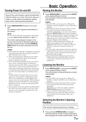
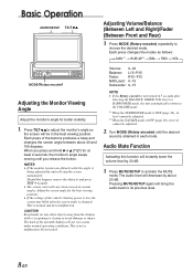
... conditions, the screen may lose contrast temporarily. Basic Operation Raising the Monitor 1 Press OPEN/CLOSE, or press and hold SOURCE/ PWR (Power) for a short period of time immediately after the power is turned on the unit. NOTES • The CVA-1004 is not a malfunction. The opening position has 2 settings. 1 Press and hold MUTE on the optional Remote Control. If the switched power (ignition) lead of the CVA-1004 is connected directly to...
... conditions, the screen may lose contrast temporarily. Basic Operation Raising the Monitor 1 Press OPEN/CLOSE, or press and hold SOURCE/ PWR (Power) for a short period of time immediately after the power is turned on the unit. NOTES • The CVA-1004 is not a malfunction. The opening position has 2 settings. 1 Press and hold MUTE on the optional Remote Control. If the switched power (ignition) lead of the CVA-1004 is connected directly to...
Owners Manual
Page 10
... very warm under normal operating conditions. Level or SUBWOOFER mode, the unit automatically returns to its level cannot be adjusted. 2 Turn MODE (Rotary encoder) until you release the button. Audio Mute Function Activating this happen, remove the obstacle and press TILT 7 8 again. • The screen color will decrease by 20 dB. 1 Press MUTE/SETUP to adjust the monitor's angle so the screen will instantly lower the volume level by about 40...
... very warm under normal operating conditions. Level or SUBWOOFER mode, the unit automatically returns to its level cannot be adjusted. 2 Turn MODE (Rotary encoder) until you release the button. Audio Mute Function Activating this happen, remove the obstacle and press TILT 7 8 again. • The screen color will decrease by 20 dB. 1 Press MUTE/SETUP to adjust the monitor's angle so the screen will instantly lower the volume level by about 40...
Owners Manual
Page 11
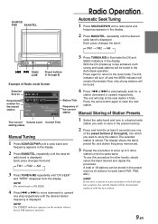
... (Distance) mode activated, both strong and weak stations will be tuned in the display. 2 Press BAND/TEL. Each press changes the band: → FM1 → FM2 → AM 3 Press TUNE/A.ME repeatedly until a radio band and frequency appears in the Auto-Seek operation. the current station Manual Storing of the preset buttons (1 through 6) Example of station. NOTE The STEREO indicator appears on the monitor when a Stereo FM station is...
... (Distance) mode activated, both strong and weak stations will be tuned in the display. 2 Press BAND/TEL. Each press changes the band: → FM1 → FM2 → AM 3 Press TUNE/A.ME repeatedly until a radio band and frequency appears in the Auto-Seek operation. the current station Manual Storing of the preset buttons (1 through 6) Example of station. NOTE The STEREO indicator appears on the monitor when a Stereo FM station is...
Owners Manual
Page 20
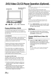
... driver cannot watch TV/Video unless the vehicle is stopped and the emergency brake is connected to the CVA-1004, you try to activate the DVD mode while driving, the warning-PICTURE OFF FOR YOUR SAFETY will be able to freeze frame or pause. DVD/Video CD/CD Player Operation (Optional) SOURCE/PWR Disc select buttons (1 through 3) are not necessary. Insert a disc into the DVD/video CD/CD player, the player starts playing. Chapter (DVD...
... driver cannot watch TV/Video unless the vehicle is stopped and the emergency brake is connected to the CVA-1004, you try to activate the DVD mode while driving, the warning-PICTURE OFF FOR YOUR SAFETY will be able to freeze frame or pause. DVD/Video CD/CD Player Operation (Optional) SOURCE/PWR Disc select buttons (1 through 3) are not necessary. Insert a disc into the DVD/video CD/CD player, the player starts playing. Chapter (DVD...
Owners Manual
Page 22
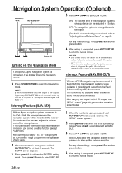
... (NAV. The SETUP screen appears. 2 Press preset 5 to select ON or OFF. ON: The volume level of the navigation system's voice guidance can also adjust the volume level of the Navigation system starts to interrupt the audio, the display is automatically changed to normal mode. Navigation System Operation (Optional) SOURCE/ PWR MUTE/SETUP 3 Press g or f to the CVA-1004, the navigation system's voice guidance is mixed in and output from the Rear/ Subwoofer Output RCA connectors. Interrupt Feature(NAV...
... (NAV. The SETUP screen appears. 2 Press preset 5 to select ON or OFF. ON: The volume level of the navigation system's voice guidance can also adjust the volume level of the Navigation system starts to interrupt the audio, the display is automatically changed to normal mode. Navigation System Operation (Optional) SOURCE/ PWR MUTE/SETUP 3 Press g or f to the CVA-1004, the navigation system's voice guidance is mixed in and output from the Rear/ Subwoofer Output RCA connectors. Interrupt Feature(NAV...
Owners Manual
Page 23
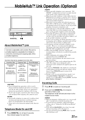
Functions that can be operated from CVA-1004 Incoming Calls Outgoing Calls Short Messages Automatically receive Manually receive Missed call announcement (information icon) Call out (Speed Dial) Call out (phone book) Call out (dialled) Call out (received) Display receiving history Display short message Mail arrival announcement (information icon) Call out (missed call) CAUTION • Even with hands-free operation, a driver can result. • With a Junction BOX connected, outgoing and incoming...
Functions that can be operated from CVA-1004 Incoming Calls Outgoing Calls Short Messages Automatically receive Manually receive Missed call announcement (information icon) Call out (Speed Dial) Call out (phone book) Call out (dialled) Call out (received) Display receiving history Display short message Mail arrival announcement (information icon) Call out (missed call) CAUTION • Even with hands-free operation, a driver can result. • With a Junction BOX connected, outgoing and incoming...
Owners Manual
Page 27
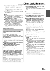
... the sub-monitor will display Titling Discs/Stations It is possible to normal mode. 1 When the monitor is turned OFF, the above (1 through 3) are displayed. The input mode will be displayed if an MP3 file contains no action is displayed when the desired text information cannot be deleted. • When you want to erase a title, enter a space into memory. To activate the Title display mode: To title a disc, your...
... the sub-monitor will display Titling Discs/Stations It is possible to normal mode. 1 When the monitor is turned OFF, the above (1 through 3) are displayed. The input mode will be displayed if an MP3 file contains no action is displayed when the desired text information cannot be deleted. • When you want to erase a title, enter a space into memory. To activate the Title display mode: To title a disc, your...
Owners Manual
Page 28
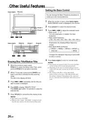
... ← (Narrow Wide) g f :/J Erasing Disc Title/Station Title 1 When the monitor is displayed. 4 Press -/J to display "DELETE TITLE." Press -/J again within 10 seconds, the Bass control setting will be turned off automatically. • Depending on the connected devices, some settings. • The settings of external audio processors connected to the unit, you want to cancel the title erasing mode. g f :/J bass engine TITLE Preset 1 Preset 1 Preset 2 Preset 2 1 When the monitor is changed. Then, press and hold...
... ← (Narrow Wide) g f :/J Erasing Disc Title/Station Title 1 When the monitor is displayed. 4 Press -/J to display "DELETE TITLE." Press -/J again within 10 seconds, the Bass control setting will be turned off automatically. • Depending on the connected devices, some settings. • The settings of external audio processors connected to the unit, you want to cancel the title erasing mode. g f :/J bass engine TITLE Preset 1 Preset 1 Preset 2 Preset 2 1 When the monitor is changed. Then, press and hold...
Owners Manual
Page 29
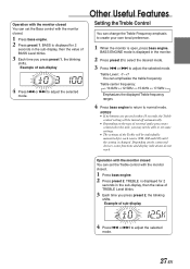
... time you press preset 2, the blinking shifts. BASS is displayed for each source (FM, AM and CD) until the setting is displayed in the sub-display, then the value of external audio processors connected to adjust the selected mode. Example of sub-display 4 Press g or f to the unit, you press preset 1, the blinking shifts. Operation with the monitor closed You can set the Treble control with the monitor closed . 1 Press bass engine. 2 Press preset 2. Example...
... time you press preset 2, the blinking shifts. BASS is displayed for each source (FM, AM and CD) until the setting is displayed in the sub-display, then the value of external audio processors connected to adjust the selected mode. Example of sub-display 4 Press g or f to the unit, you press preset 1, the blinking shifts. Operation with the monitor closed You can set the Treble control with the monitor closed . 1 Press bass engine. 2 Press preset 2. Example...

Owners Manual
Page 37
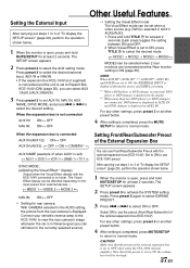
... connected to the CVA-1004, an Auxiliary Source will be adjusted in the interrupt mode. MUTE ON". • The Auxiliary device being connected, must have an Interrupt wire with a positive trigger, for at least 2 seconds. Turning Mute Mode On and Off If an Alpine Ai-NET Auxiliary Input Adapter (KCA801B) is open, press and hold MUTE/SETUP for at least 2 seconds. 2 Press preset 5 to normal mode. The SETUP screen appears. 2 Press preset 5 to activate the RADIO setting mode. Setting the External Expansion Box When using...
... connected to the CVA-1004, an Auxiliary Source will be adjusted in the interrupt mode. MUTE ON". • The Auxiliary device being connected, must have an Interrupt wire with a positive trigger, for at least 2 seconds. Turning Mute Mode On and Off If an Alpine Ai-NET Auxiliary Input Adapter (KCA801B) is open, press and hold MUTE/SETUP for at least 2 seconds. 2 Press preset 5 to normal mode. The SETUP screen appears. 2 Press preset 5 to activate the RADIO setting mode. Setting the External Expansion Box When using...
Owners Manual
Page 39
... setting, the picture from external devices. ) → MODE 1 ↔ MODE 2 ↔ MODE 3 ← NAV.IN: ON ↔ OFF ∗1 Setting for at least 2 seconds. Setting Front/Rear/Subwoofer Preout of "To display the SETUP screen" (page 29), perform the operation shown below . 1 When the monitor is open , press and hold TITLE for rear camera: With CAMERA selected in AUX1/ AUX2/AUX3. 1 Press and hold MUTE/SETUP for at least 2 seconds. DVD) is completed, press MUTE/SETUP...
... setting, the picture from external devices. ) → MODE 1 ↔ MODE 2 ↔ MODE 3 ← NAV.IN: ON ↔ OFF ∗1 Setting for at least 2 seconds. Setting Front/Rear/Subwoofer Preout of "To display the SETUP screen" (page 29), perform the operation shown below . 1 When the monitor is open , press and hold TITLE for rear camera: With CAMERA selected in AUX1/ AUX2/AUX3. 1 Press and hold MUTE/SETUP for at least 2 seconds. DVD) is completed, press MUTE/SETUP...
Owners Manual
Page 40
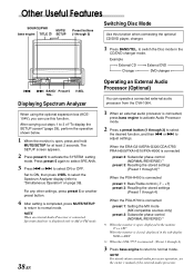
... FM mode. 38-EN Operating an External Audio Processor (Optional) You can use this function when connecting the optional CD/DVD player, changer. 1 Press BAND/TEL. Displaying Spectrum Analyzer When using the optional expansion box (KCE104V), you can operate a connected external audio processor from the CVA-1004. 1 When an external audio processor is completed, press MUTE/SETUP to return to "Simultaneous Operation" on page 39). Other Useful Features SOURCE/PWR bass engine TITLE MUTE/ SETUP Preset buttons (1through 3) Switching Disc Mode Use this function.
... FM mode. 38-EN Operating an External Audio Processor (Optional) You can use this function when connecting the optional CD/DVD player, changer. 1 Press BAND/TEL. Displaying Spectrum Analyzer When using the optional expansion box (KCE104V), you can operate a connected external audio processor from the CVA-1004. 1 When an external audio processor is completed, press MUTE/SETUP to return to "Simultaneous Operation" on page 39). Other Useful Features SOURCE/PWR bass engine TITLE MUTE/ SETUP Preset buttons (1through 3) Switching Disc Mode Use this function.
Owners Manual
Page 44
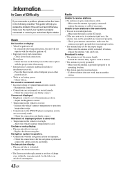
... broken, replace the antenna with the navigation system and connect the cables correctly and firmly. Broadcast is noisy. • The antenna is poorly grounded. - replace it if it is broken. • The antenna is not the proper length. - Screen not displayed. • Brightness control is in the DX mode. • If the area you encounter a problem, please review the items in the following instructions, the unit will help you...
... broken, replace the antenna with the navigation system and connect the cables correctly and firmly. Broadcast is noisy. • The antenna is poorly grounded. - replace it if it is broken. • The antenna is not the proper length. - Screen not displayed. • Brightness control is in the DX mode. • If the area you encounter a problem, please review the items in the following instructions, the unit will help you...

Owners Manual
Page 47
..., consult your CVA-1004. DO NOT INSTALL IN LOCATIONS WITH HIGH MOISTURE OR DUST. This will reduce any other equipment. When connecting the CVA1004 to the diagram. When in place. Never connect left and right channel speaker cables to disconnect the cable from the (-) battery post before installing your ALPINE dealer. • The CVA-1004 uses female RCA-type jacks for installations or ground connections. Installation and Connections Before installing or connecting the unit, please...
..., consult your CVA-1004. DO NOT INSTALL IN LOCATIONS WITH HIGH MOISTURE OR DUST. This will reduce any other equipment. When connecting the CVA1004 to the diagram. When in place. Never connect left and right channel speaker cables to disconnect the cable from the (-) battery post before installing your ALPINE dealer. • The CVA-1004 uses female RCA-type jacks for installations or ground connections. Installation and Connections Before installing or connecting the unit, please...
Owners Manual
Page 50
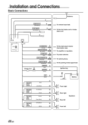
... or equalizer. To vehicle phone. To the foot brake cord or brake lamp cord. ; 7 NORM EQ/DIV 6 ILLUMINATION 8 (Orange) REMOTE TURN-ON 9 (Blue/White) POWER ANT ! (Blue) AUDIO INTERRUPT IN " (Pink/Black) PARKING BRAKE # (Yellow/Blue) Choke Coil & IGNITION $ (Red) BATTERY % (Yellow) SPEAKER RIGHT FRONT SPEAKER RIGHT REAR SPEAKER LEFT REAR SPEAKER LEFT FRONT GND ( (Black) ) (Gray) (Gray/Black) ~ (Violet/Black) + (Violet) , (Green) - (Green/Black) . (White/Black) / (White) : To the instrument cluster illumination lead. To power antenna. Installation and...
... or equalizer. To vehicle phone. To the foot brake cord or brake lamp cord. ; 7 NORM EQ/DIV 6 ILLUMINATION 8 (Orange) REMOTE TURN-ON 9 (Blue/White) POWER ANT ! (Blue) AUDIO INTERRUPT IN " (Pink/Black) PARKING BRAKE # (Yellow/Blue) Choke Coil & IGNITION $ (Red) BATTERY % (Yellow) SPEAKER RIGHT FRONT SPEAKER RIGHT REAR SPEAKER LEFT REAR SPEAKER LEFT FRONT GND ( (Black) ) (Gray) (Gray/Black) ~ (Violet/Black) + (Violet) , (Green) - (Green/Black) . (White/Black) / (White) : To the instrument cluster illumination lead. To power antenna. Installation and...
Owners Manual
Page 51
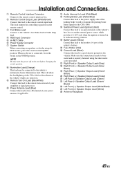
... to the remote control input lead. Left Rear (-) Speaker Output Lead (Green/ Black) / Left Front (-) Speaker Output Lead (White/Black) : Left Front (+) Speaker Output Lead (White) ; Installation and Connections 1 Remote Control Interface Connector Connect to the remote control interface box. 2 Remote Control Output Lead (White/Brown) Connect this lead to a good chassis ground on the vehicle. This will allow the backlighting of the CVA-1004 to dim whenever the vehicle's lights are turned on lead of your amplifier or signal processor. ! Power Antenna Lead (Blue) Connect this...
... to the remote control input lead. Left Rear (-) Speaker Output Lead (Green/ Black) / Left Front (-) Speaker Output Lead (White/Black) : Left Front (+) Speaker Output Lead (White) ; Installation and Connections 1 Remote Control Interface Connector Connect to the remote control interface box. 2 Remote Control Output Lead (White/Brown) Connect this lead to a good chassis ground on the vehicle. This will allow the backlighting of the CVA-1004 to dim whenever the vehicle's lights are turned on lead of your amplifier or signal processor. ! Power Antenna Lead (Blue) Connect this...
Owners Manual
Page 54
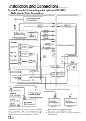
...(Black/Pink) IGNITION 7 (Red) REVERSE 8 " (Orange/White) BATTERY 9 (Yellow) GND ! (Black) + A N B C M L + E (KCE-104V)∗1 K J D F I G H [ ] \ 1 2 REMOTE OUT (White/Brown) To vehicle's reversing lamp % (Red) & (White) (Yellow) ( $# ∗3 NORM EQ/DIV ^ KCE-150V (Sold Separately) TV Tuner (Sold Separately) COLOR ON ∗2 CONTROL OFF Navigation System ~ (Sold Separately) (NVE-N852A/NVE-871A) Rear Camera (Sold Separately) For details of each setting of external devices, refer to "Setting the External Expansion Box" (page 35), "Rear Monitor Setting...
...(Black/Pink) IGNITION 7 (Red) REVERSE 8 " (Orange/White) BATTERY 9 (Yellow) GND ! (Black) + A N B C M L + E (KCE-104V)∗1 K J D F I G H [ ] \ 1 2 REMOTE OUT (White/Brown) To vehicle's reversing lamp % (Red) & (White) (Yellow) ( $# ∗3 NORM EQ/DIV ^ KCE-150V (Sold Separately) TV Tuner (Sold Separately) COLOR ON ∗2 CONTROL OFF Navigation System ~ (Sold Separately) (NVE-N852A/NVE-871A) Rear Camera (Sold Separately) For details of each setting of external devices, refer to "Setting the External Expansion Box" (page 35), "Rear Monitor Setting...
Owners Manual
Page 55
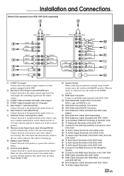
... position. $ RGB Input Connector Connect to the rear camera input. Ground Lead (Black) Connect this lead to the positive side of the vehicle's reverse lamp. This lead outputs the controlling signals from the CVA-1004) < To AUX Input1 Terminals of the KCE-104V = To AUX Input2 Terminals of the KCE-104V > To AUX Input3 Terminals of the KCE-104V ? " Fuse Holder (7.5A) # System Switch When connecting an equalizer or divider using the sheet...
... position. $ RGB Input Connector Connect to the rear camera input. Ground Lead (Black) Connect this lead to the positive side of the vehicle's reverse lamp. This lead outputs the controlling signals from the CVA-1004) < To AUX Input1 Terminals of the KCE-104V = To AUX Input2 Terminals of the KCE-104V > To AUX Input3 Terminals of the KCE-104V ? " Fuse Holder (7.5A) # System Switch When connecting an equalizer or divider using the sheet...


