User Guide
Page 9
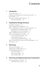
...2: Installing into a Rack or Tower (optional) 2-3 Installing into an Equipment Rack 2-4 Installing into a Tower Assembly 2-7 Step 3: Installing the Drive Carriers 2-9 Step 4: Connecting the I/O Cables 2-9 Connecting SATA Cables 2-10 Connecting FC Cables 2-11 Connecting Ultra320 SCSI Cables 2-12 Step 5: ...Connect Power Cords to the APC Modules. 2-13 Next Steps 2-13 3 Monitoring About the ES Module 3-2 Silencing the Audible Alarm 3-2 Understanding the LEDs 3-3 Front Panel LEDs 3-3 Drive Carrier LEDs 3-4 APC Module LEDs 3-5 4 Removing and Replacing Enclosure Components Hot-swapping...
...2: Installing into a Rack or Tower (optional) 2-3 Installing into an Equipment Rack 2-4 Installing into a Tower Assembly 2-7 Step 3: Installing the Drive Carriers 2-9 Step 4: Connecting the I/O Cables 2-9 Connecting SATA Cables 2-10 Connecting FC Cables 2-11 Connecting Ultra320 SCSI Cables 2-12 Step 5: ...Connect Power Cords to the APC Modules. 2-13 Next Steps 2-13 3 Monitoring About the ES Module 3-2 Silencing the Audible Alarm 3-2 Understanding the LEDs 3-3 Front Panel LEDs 3-3 Drive Carrier LEDs 3-4 APC Module LEDs 3-5 4 Removing and Replacing Enclosure Components Hot-swapping...
User Guide
Page 10
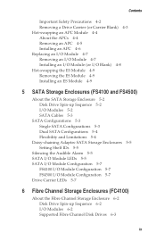
... an ES Module 4-9 5 SATA Storage Enclosures (FS4100 and FS4500) About the SATA Storage Enclosure 5-2 Disk Drive Spin-up Sequence 5-2 I/O Modules 5-2 SATA Cables 5-3 SATA Configurations 5-3 Single SATA Configurations 5-3 Dual SATA Configurations 5-4 Flexibility and Limitations 5-4 Daisy-chaining Adaptec SATA Storage Enclosures 5-5 Setting Shelf IDs 5-5 Silencing the Audible Alarm 5-5 SATA I/O Module LEDs 5-5 SATA I/O Module Configuration 5-7 FS4100 I/O Module Configuration 5-7 FS4500 I/O Module Configuration 5-7 Drive Carrier LEDs...
... an ES Module 4-9 5 SATA Storage Enclosures (FS4100 and FS4500) About the SATA Storage Enclosure 5-2 Disk Drive Spin-up Sequence 5-2 I/O Modules 5-2 SATA Cables 5-3 SATA Configurations 5-3 Single SATA Configurations 5-3 Dual SATA Configurations 5-4 Flexibility and Limitations 5-4 Daisy-chaining Adaptec SATA Storage Enclosures 5-5 Setting Shelf IDs 5-5 Silencing the Audible Alarm 5-5 SATA I/O Module LEDs 5-5 SATA I/O Module Configuration 5-7 FS4100 I/O Module Configuration 5-7 FS4500 I/O Module Configuration 5-7 Drive Carrier LEDs...
User Guide
Page 11
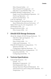
... Operation 6-7 Daisy-chaining FC Storage Enclosures 6-7 Speed Mismatches between Enclosures 6-7 Option Slot Loop AL_PA Assignments 6-7 LIO Module LEDs 6-7 Storage Enclosure LEDs 6-8 Drive Carrier LEDs 6-8 7 Ultra320 SCSI Storage Enclosures About the Adaptec SC4100 Storage Enclosure 7-2 Disk Drive Spin-up Sequence 7-2 I/O Modules 7-2 Drive Carrier LEDs 7-3 Cables and Termination 7-3 Ultra320 SCSI Split-bus Configurations 7-4 Split-bus SCSI IDs 7-4 Configuring...
... Operation 6-7 Daisy-chaining FC Storage Enclosures 6-7 Speed Mismatches between Enclosures 6-7 Option Slot Loop AL_PA Assignments 6-7 LIO Module LEDs 6-7 Storage Enclosure LEDs 6-8 Drive Carrier LEDs 6-8 7 Ultra320 SCSI Storage Enclosures About the Adaptec SC4100 Storage Enclosure 7-2 Disk Drive Spin-up Sequence 7-2 I/O Modules 7-2 Drive Carrier LEDs 7-3 Cables and Termination 7-3 Ultra320 SCSI Split-bus Configurations 7-4 Split-bus SCSI IDs 7-4 Configuring...
User Guide
Page 12
... SCSI Storage Enclosure Technical Specifications 8-5 Disk Drives 8-5 SCSI Bus 8-5 SCSI Midplane 8-5 I/O Modules 8-6 I/O Module Configurations 8-7 Cable Lengths Supported 8-7 SATA Storage Enclosure Technical Specifications 8-7 Currently Supported Disk Drives 8-7 Serial ATA Interface 8-8 SATA I/O Modules 8-8 SATA Cables 8-8 SATA Configurations 8-8 FC Storage Enclosure Technical Specifications 8-9 Disk Drives 8-9 Daisy Chaining Adaptec FC Enclosures 8-9 A Configuring the RAID Controller (FS4500 only) Communication Parameters A-2 Navigating the Terminal...
... SCSI Storage Enclosure Technical Specifications 8-5 Disk Drives 8-5 SCSI Bus 8-5 SCSI Midplane 8-5 I/O Modules 8-6 I/O Module Configurations 8-7 Cable Lengths Supported 8-7 SATA Storage Enclosure Technical Specifications 8-7 Currently Supported Disk Drives 8-7 Serial ATA Interface 8-8 SATA I/O Modules 8-8 SATA Cables 8-8 SATA Configurations 8-8 FC Storage Enclosure Technical Specifications 8-9 Disk Drives 8-9 Daisy Chaining Adaptec FC Enclosures 8-9 A Configuring the RAID Controller (FS4500 only) Communication Parameters A-2 Navigating the Terminal...
User Guide
Page 16
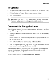
... Enclosure also features one hot-swappable (but non-redundant) Enclosure Services (ES) module, which includes the Alarm Mute button. Overview of your Adaptec reseller for monitoring status) Drive carriers are sold separately. Introduction Kit Contents ■ Adaptec Storage Enclosure (FS4100, FS4500, SC4100, or FC4100) ■ CD, including software, drivers, and documentation ■ Two power cables...
... Enclosure also features one hot-swappable (but non-redundant) Enclosure Services (ES) module, which includes the Alarm Mute button. Overview of your Adaptec reseller for monitoring status) Drive carriers are sold separately. Introduction Kit Contents ■ Adaptec Storage Enclosure (FS4100, FS4500, SC4100, or FC4100) ■ CD, including software, drivers, and documentation ■ Two power cables...
User Guide
Page 17
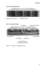
Front of Storage Enclosure Introduction Disk Drive Carrier LEDs Disk Drive Carriers Rear of Storage Enclosure ES Module Alarm Mute Button APC Module I/O Module 2 I/O Module1 I/O Option Modules (FC Model shown here) Figure 1-1 Overview of Storage Enclosure APC Module 1-4
Front of Storage Enclosure Introduction Disk Drive Carrier LEDs Disk Drive Carriers Rear of Storage Enclosure ES Module Alarm Mute Button APC Module I/O Module 2 I/O Module1 I/O Option Modules (FC Model shown here) Figure 1-1 Overview of Storage Enclosure APC Module 1-4
User Guide
Page 19
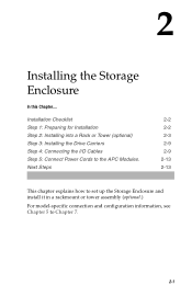
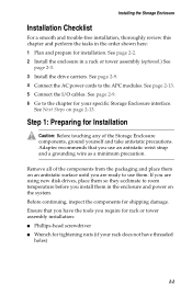
Next Steps 2-2 2-2 2-3 2-9 2-9 2-13 2-13 This chapter explains how to set up the Storage Enclosure and install it in a rackmount or tower assembly (optional.) For model-specific connection and configuration information, see Chapter 5 to the APC Modules. Installation Checklist Step 1: Preparing for Installation Step 2: Installing into a Rack or Tower (optional) Step 3: Installing the Drive Carriers Step 4: Connecting the I/O Cables Step 5: Connect Power Cords to Chapter 7. 2-1 2 Installing the Storage Enclosure In this Chapter....
Next Steps 2-2 2-2 2-3 2-9 2-9 2-13 2-13 This chapter explains how to set up the Storage Enclosure and install it in a rackmount or tower assembly (optional.) For model-specific connection and configuration information, see Chapter 5 to the APC Modules. Installation Checklist Step 1: Preparing for Installation Step 2: Installing into a Rack or Tower (optional) Step 3: Installing the Drive Carriers Step 4: Connecting the I/O Cables Step 5: Connect Power Cords to Chapter 7. 2-1 2 Installing the Storage Enclosure In this Chapter....
User Guide
Page 20
See page 2-9. 6 Go to the APC modules. Caution: Before touching any of the components from ...review this chapter and perform the tasks in a rack or tower assembly (optional.) See page 2-3. 3 Install the drive carriers. Adaptec recommends that you have threaded holes) 2-2 Ensure that you require for rack or tower assembly installation: ■ Phillips-...antistatic precautions. See Next Steps on the system. Step 1: Preparing for shipping damage. If you are using new disk drives, place them in the enclosure and power on page 2-13. See page 2-13. 5 Connect the I/O cables. See...
See page 2-9. 6 Go to the APC modules. Caution: Before touching any of the components from ...review this chapter and perform the tasks in a rack or tower assembly (optional.) See page 2-3. 3 Install the drive carriers. Adaptec recommends that you have threaded holes) 2-2 Ensure that you require for rack or tower assembly installation: ■ Phillips-...antistatic precautions. See Next Steps on the system. Step 1: Preparing for shipping damage. If you are using new disk drives, place them in the enclosure and power on page 2-13. See page 2-13. 5 Connect the I/O cables. See...
User Guide
Page 27
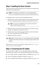
... of the enclosure to the APC Modules. When all drive carriers are installed, continue with the LEDs on the left side of the carrier assembly and clicks into the slot until the lever starts to your specific Storage Enclosure interface: ■ For a SATA interface (Adaptec FS4100 or FS4500), see page 2-10. ■ For an...
... of the enclosure to the APC Modules. When all drive carriers are installed, continue with the LEDs on the left side of the carrier assembly and clicks into the slot until the lever starts to your specific Storage Enclosure interface: ■ For a SATA interface (Adaptec FS4100 or FS4500), see page 2-10. ■ For an...
User Guide
Page 28
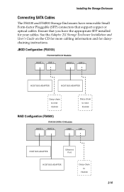
... (FS4500) FS4500 SATA I/O Module HOST 1 HOST 2 ENET EXP HOST BUS ADAPTER Ethernet Port HOST BUS ADAPTER Daisy-chain to FS4100 2-10 Installing the Storage Enclosure Connecting SATA Cables The FS4100 and FS4500 Storage... Enclosures have removable Small Form-factor Pluggable (SFP) connectors that you have the appropriate SFP installed for daisychaining instructions. See the Adaptec...
... (FS4500) FS4500 SATA I/O Module HOST 1 HOST 2 ENET EXP HOST BUS ADAPTER Ethernet Port HOST BUS ADAPTER Daisy-chain to FS4100 2-10 Installing the Storage Enclosure Connecting SATA Cables The FS4100 and FS4500 Storage... Enclosures have removable Small Form-factor Pluggable (SFP) connectors that you have the appropriate SFP installed for daisychaining instructions. See the Adaptec...
User Guide
Page 29
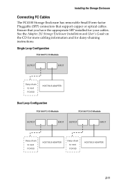
See the Adaptec 2U Storage Enclosure Installation and User's Guide on the CD for more cabling information and for your cables. Single Loop Configuration FC4100 FC I/O Module OUTPUT INPUT Daisy-chain to next FC4100 HOST BUS ADAPTER Dual Loop Configuration FC4100 FC I/O Module FC4100 FC I/O Module OUTPUT INPUT OUTPUT INPUT Daisy-chain to next FC4100...
See the Adaptec 2U Storage Enclosure Installation and User's Guide on the CD for more cabling information and for your cables. Single Loop Configuration FC4100 FC I/O Module OUTPUT INPUT Daisy-chain to next FC4100 HOST BUS ADAPTER Dual Loop Configuration FC4100 FC I/O Module FC4100 FC I/O Module OUTPUT INPUT OUTPUT INPUT Daisy-chain to next FC4100...
User Guide
Page 30
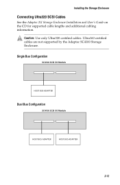
Caution: Use only Ultra320 certified cables. Single Bus Configuration SC4100 SCSI I/O Module HOST BUS ADAPTER Dual Bus Configuration SC4100 SCSI I/O Module HOST BUS ADAPTER HOST BUS ADAPTER 2-12 Ultra160 certified cables are not supported by the Adaptec SC4100 Storage Enclosure. Installing the Storage Enclosure Connecting Ultra320 SCSI Cables See the Adaptec 2U Storage Enclosure Installation and User's Guide on the CD for supported cable lengths and additional cabling information. !
Caution: Use only Ultra320 certified cables. Single Bus Configuration SC4100 SCSI I/O Module HOST BUS ADAPTER Dual Bus Configuration SC4100 SCSI I/O Module HOST BUS ADAPTER HOST BUS ADAPTER 2-12 Ultra160 certified cables are not supported by the Adaptec SC4100 Storage Enclosure. Installing the Storage Enclosure Connecting Ultra320 SCSI Cables See the Adaptec 2U Storage Enclosure Installation and User's Guide on the CD for supported cable lengths and additional cabling information. !
User Guide
Page 31
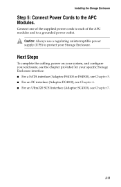
... of the supplied power cords to each of the APC modules and to protect your specific Storage Enclosure interface: ■ For a SATA interface (Adaptec FS4100 or FS4500), see Chapter 5. ■ For an FC interface (Adaptec FC4100), see Chapter 6. ■ For an Ultra320 SCSI interface (Adaptec SC4100), see the chapter provided for your Storage Enclosure. Installing...
... of the supplied power cords to each of the APC modules and to protect your specific Storage Enclosure interface: ■ For a SATA interface (Adaptec FS4100 or FS4500), see Chapter 5. ■ For an FC interface (Adaptec FC4100), see Chapter 6. ■ For an Ultra320 SCSI interface (Adaptec SC4100), see the chapter provided for your Storage Enclosure. Installing...
User Guide
Page 32
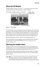
The chapter describes the monitoring features of the Adaptec Storage Enclosure, including the ES module, the alarm, and the LEDs, and explains how to monitor the status of LEDs and an audible alarm. 3 Monitoring In this Chapter.... About the ES Module 3-2 Silencing the Audible Alarm 3-2 Understanding the LEDs 3-3 Your Adaptec Storage Enclosure's status is monitored by the ES module, which reports enclosure status through the use these features to use of your enclosure's components. 3-1
The chapter describes the monitoring features of the Adaptec Storage Enclosure, including the ES module, the alarm, and the LEDs, and explains how to monitor the status of LEDs and an audible alarm. 3 Monitoring In this Chapter.... About the ES Module 3-2 Silencing the Audible Alarm 3-2 Understanding the LEDs 3-3 Your Adaptec Storage Enclosure's status is monitored by the ES module, which reports enclosure status through the use these features to use of your enclosure's components. 3-1
User Guide
Page 33
..., see Hot-swapping the ES Module on the APC modules, drive carriers, and enclosure) and an audible alarm. See the Installation and User's Guide on the rear of the Storage Enclosure, between the two APC modules. Monitoring About the ES Module The ES module, shown in Figure 3-1, is located on your Adaptec Storage Enclosure CD for the...
..., see Hot-swapping the ES Module on the APC modules, drive carriers, and enclosure) and an audible alarm. See the Installation and User's Guide on the rear of the Storage Enclosure, between the two APC modules. Monitoring About the ES Module The ES module, shown in Figure 3-1, is located on your Adaptec Storage Enclosure CD for the...
User Guide
Page 35
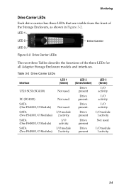
...) SATA (One FS4100 I/O Module) SATA (Two FS4100 I/O Modules) SATA (One FS4500 I/O Module) SATA (Two FS4500 I /O activity. I /O Modules) LED 1 (Green) Not used . I /O activity. Drive present Drive present Drive present LED 3 (Green) I /O activity. Not used . I /O module 1 activity. Drive present. I /O module 2 activity. Monitoring Drive Carrier LEDs Each drive carrier has three LEDs that are visible from the front of the three LEDs for all Adaptec Storage Enclosure models...
...) SATA (One FS4100 I/O Module) SATA (Two FS4100 I/O Modules) SATA (One FS4500 I/O Module) SATA (Two FS4500 I /O activity. I /O Modules) LED 1 (Green) Not used . I /O activity. Drive present Drive present Drive present LED 3 (Green) I /O activity. Not used . I /O module 1 activity. Drive present. I /O module 2 activity. Monitoring Drive Carrier LEDs Each drive carrier has three LEDs that are visible from the front of the three LEDs for all Adaptec Storage Enclosure models...
User Guide
Page 36
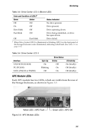
... illuminated, indicating a shelf fault. (See Table 3-1 on page 3-3.) Table 3-4 Drive Carrier LED 3 Interface U320 SCSI (SC4100) FC (FC4100) SATA (FS4100 or FS4500) Spin Up On Blinking Off Drive Status Online I/O Activity Off On (briefly) On Off (briefly) On Off (briefly) APC Module LEDs Each APC module has two LEDs, which are visible from the rear...
... illuminated, indicating a shelf fault. (See Table 3-1 on page 3-3.) Table 3-4 Drive Carrier LED 3 Interface U320 SCSI (SC4100) FC (FC4100) SATA (FS4100 or FS4500) Spin Up On Blinking Off Drive Status Online I/O Activity Off On (briefly) On Off (briefly) On Off (briefly) APC Module LEDs Each APC module has two LEDs, which are visible from the rear...
User Guide
Page 37
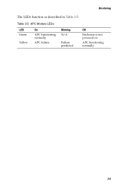
Monitoring The LEDs function as described in Table 3-5: Table 3-5 APC Module LEDs LED Green Yellow On APC functioning normally APC failure Blinking N/A Failure predicted Off Enclosure is not powered on APC functioning normally 3-6
Monitoring The LEDs function as described in Table 3-5: Table 3-5 APC Module LEDs LED Green Yellow On APC functioning normally APC failure Blinking N/A Failure predicted Off Enclosure is not powered on APC functioning normally 3-6
User Guide
Page 38
...-static discharge (ESD) precautions may lead to damage to your Adaptec Storage Enclosure. ! Failure to take antistatic precautions. Caution: Before touching any of your disk drives and enclosure electronics. 4-1 Hot-swapping Drive Carriers Hot-swapping an APC Module Replacing an I/O Module Hot-swapping the ES Module 4-2 4-4 4-7 4-10 The Storage Enclosure features described in Chapter 3 help you...
...-static discharge (ESD) precautions may lead to damage to your Adaptec Storage Enclosure. ! Failure to take antistatic precautions. Caution: Before touching any of your disk drives and enclosure electronics. 4-1 Hot-swapping Drive Carriers Hot-swapping an APC Module Replacing an I/O Module Hot-swapping the ES Module 4-2 4-4 4-7 4-10 The Storage Enclosure features described in Chapter 3 help you...
User Guide
Page 41
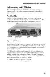
... a single APC for proper operation and cooling. Failed APC modules can be caused by the other APC in Figure 4-1. Handle Power Cord Connector Power Switch Handle Figure 4-1 APC Module Your Adaptec Storage Enclosure requires both APCs to be running for a brief...Removing and Replacing Enclosure Components Hot-swapping an APC Module This section provides basic information about your Storage Enclosure's APC modules, including removal and installation instructions. However, it can be hot-swapped. 4-4 Your Adaptec Storage Enclosure includes two APCs, located on separate ...
... a single APC for proper operation and cooling. Failed APC modules can be caused by the other APC in Figure 4-1. Handle Power Cord Connector Power Switch Handle Figure 4-1 APC Module Your Adaptec Storage Enclosure requires both APCs to be running for a brief...Removing and Replacing Enclosure Components Hot-swapping an APC Module This section provides basic information about your Storage Enclosure's APC modules, including removal and installation instructions. However, it can be hot-swapped. 4-4 Your Adaptec Storage Enclosure includes two APCs, located on separate ...