User Guide
Page 3
...P.M., Pacific Time. ■ For RAID and Fibre Channel products call +1 408-934-7274, Monday to Adaptec's Technical Support Specialists at ask.adaptec.com. Technical Support Identification (TSID) Number ■ Before contacting Technical Support, you need further assistance, use the support options listed below . ■ If you...most of the TSID label to the CD jacket so that you can order cables online at www.adaptec.com. ■ For information about installing or using your service, have questions about Adaptec's support options, call +1 408-957-2550, 24 hours per day, 7 days per...
...P.M., Pacific Time. ■ For RAID and Fibre Channel products call +1 408-934-7274, Monday to Adaptec's Technical Support Specialists at ask.adaptec.com. Technical Support Identification (TSID) Number ■ Before contacting Technical Support, you need further assistance, use the support options listed below . ■ If you...most of the TSID label to the CD jacket so that you can order cables online at www.adaptec.com. ■ For information about installing or using your service, have questions about Adaptec's support options, call +1 408-957-2550, 24 hours per day, 7 days per...
User Guide
Page 9
...Information You Need in this Guide 1-2 Kit Contents 1-3 Overview of the Storage Enclosure 1-3 Drive Slot Numbers 1-5 2 Installing the Storage Enclosure Installation Checklist 2-2 Step 1: Preparing for Installation 2-2 Step 2: Installing into a Rack or Tower (optional) 2-3 Installing into an Equipment Rack 2-4 Installing into a Tower Assembly 2-7 Step 3: Installing the Drive Carriers 2-9 Step 4: Connecting the I/O Cables 2-9 Connecting SATA Cables 2-10 Connecting FC Cables 2-11 Connecting Ultra320 SCSI Cables 2-12 Step 5: Connect Power Cords to the APC Modules. 2-13 Next Steps 2-13 3 Monitoring...
...Information You Need in this Guide 1-2 Kit Contents 1-3 Overview of the Storage Enclosure 1-3 Drive Slot Numbers 1-5 2 Installing the Storage Enclosure Installation Checklist 2-2 Step 1: Preparing for Installation 2-2 Step 2: Installing into a Rack or Tower (optional) 2-3 Installing into an Equipment Rack 2-4 Installing into a Tower Assembly 2-7 Step 3: Installing the Drive Carriers 2-9 Step 4: Connecting the I/O Cables 2-9 Connecting SATA Cables 2-10 Connecting FC Cables 2-11 Connecting Ultra320 SCSI Cables 2-12 Step 5: Connect Power Cords to the APC Modules. 2-13 Next Steps 2-13 3 Monitoring...
User Guide
Page 10
... 4-5 Installing an APC 4-6 Replacing an I/O Module 4-7 Removing an I/O Module 4-7 Installing an I/O Module (or I/O Blank) 4-8 Hot-swapping the ES Module 4-9 Removing the ES Module 4-9 Installing an ES Module 4-9 5 SATA Storage Enclosures (FS4100 and FS4500) About the SATA Storage Enclosure 5-2 Disk Drive Spin-up Sequence 5-2 I/O Modules 5-2 SATA Cables 5-3 SATA Configurations 5-3 Single SATA Configurations 5-3 Dual SATA Configurations 5-4 Flexibility and Limitations 5-4 Daisy-chaining Adaptec SATA Storage Enclosures 5-5 Setting Shelf IDs 5-5 Silencing the Audible Alarm 5-5 SATA I/O Module LEDs...
... 4-5 Installing an APC 4-6 Replacing an I/O Module 4-7 Removing an I/O Module 4-7 Installing an I/O Module (or I/O Blank) 4-8 Hot-swapping the ES Module 4-9 Removing the ES Module 4-9 Installing an ES Module 4-9 5 SATA Storage Enclosures (FS4100 and FS4500) About the SATA Storage Enclosure 5-2 Disk Drive Spin-up Sequence 5-2 I/O Modules 5-2 SATA Cables 5-3 SATA Configurations 5-3 Single SATA Configurations 5-3 Dual SATA Configurations 5-4 Flexibility and Limitations 5-4 Daisy-chaining Adaptec SATA Storage Enclosures 5-5 Setting Shelf IDs 5-5 Silencing the Audible Alarm 5-5 SATA I/O Module LEDs...
User Guide
Page 11
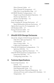
... Enclosure LEDs 6-8 Drive Carrier LEDs 6-8 7 Ultra320 SCSI Storage Enclosures About the Adaptec SC4100 Storage Enclosure 7-2 Disk Drive Spin-up Sequence 7-2 I/O Modules 7-2 Drive Carrier LEDs 7-3 Cables and Termination 7-3 Ultra320 SCSI Split-bus Configurations 7-4 Split-bus SCSI IDs 7-4 Configuring a Split-bus Enclosure 7-5 Ultra320 SCSI Joined-bus Configurations 7-5 Joined-bus SCSI IDs 7-5 Configuring Joined-Bus 7-6 8 Technical Specifications General Specifications 8-2 System 8-2 Redundant Components 8-2 Field Replaceable Units 8-2 Storage Enclosure Physical Dimensions 8-2 Advanced Power...
... Enclosure LEDs 6-8 Drive Carrier LEDs 6-8 7 Ultra320 SCSI Storage Enclosures About the Adaptec SC4100 Storage Enclosure 7-2 Disk Drive Spin-up Sequence 7-2 I/O Modules 7-2 Drive Carrier LEDs 7-3 Cables and Termination 7-3 Ultra320 SCSI Split-bus Configurations 7-4 Split-bus SCSI IDs 7-4 Configuring a Split-bus Enclosure 7-5 Ultra320 SCSI Joined-bus Configurations 7-5 Joined-bus SCSI IDs 7-5 Configuring Joined-Bus 7-6 8 Technical Specifications General Specifications 8-2 System 8-2 Redundant Components 8-2 Field Replaceable Units 8-2 Storage Enclosure Physical Dimensions 8-2 Advanced Power...
User Guide
Page 15
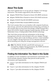
... of Fibre Channel (FC), Serial ATA (SATA), Small Computer System Interface (SCSI), and Redundant Array of Independent Disks (RAID) technology. This Guide does not provide any information on your Adaptec Storage Enclosure. Please refer to the Installation and User's Guide included on the storage management software tools included with computer hardware, data storage, and network administration terminology and tasks. the FS4500 enclosure is managed by Spheras...
... of Fibre Channel (FC), Serial ATA (SATA), Small Computer System Interface (SCSI), and Redundant Array of Independent Disks (RAID) technology. This Guide does not provide any information on your Adaptec Storage Enclosure. Please refer to the Installation and User's Guide included on the storage management software tools included with computer hardware, data storage, and network administration terminology and tasks. the FS4500 enclosure is managed by Spheras...
User Guide
Page 16
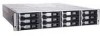
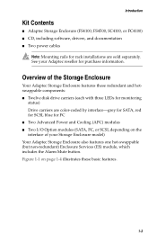
Introduction Kit Contents ■ Adaptec Storage Enclosure (FS4100, FS4500, SC4100, or FC4100) ■ CD, including software, drivers, and documentation ■ Two power cables Note: Mounting rails for rack installations are color-coded by interface-grey for SATA, red for SCSI, blue for FC ■ Two Advanced Power and Cooling (APC) modules ■ Two I/O Option modules (SATA, FC, or SCSI, depending on page 1-4 illustrates these...
Introduction Kit Contents ■ Adaptec Storage Enclosure (FS4100, FS4500, SC4100, or FC4100) ■ CD, including software, drivers, and documentation ■ Two power cables Note: Mounting rails for rack installations are color-coded by interface-grey for SATA, red for SCSI, blue for FC ■ Two Advanced Power and Cooling (APC) modules ■ Two I/O Option modules (SATA, FC, or SCSI, depending on page 1-4 illustrates these...
User Guide
Page 19
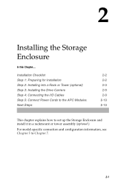
Next Steps 2-2 2-2 2-3 2-9 2-9 2-13 2-13 This chapter explains how to set up the Storage Enclosure and install it in a rackmount or tower assembly (optional.) For model-specific connection and configuration information, see Chapter 5 to the APC Modules. Installation Checklist Step 1: Preparing for Installation Step 2: Installing into a Rack or Tower (optional) Step 3: Installing the Drive Carriers Step 4: Connecting the I/O Cables Step 5: Connect Power Cords to Chapter 7. 2-1 2 Installing the Storage Enclosure In this Chapter....
Next Steps 2-2 2-2 2-3 2-9 2-9 2-13 2-13 This chapter explains how to set up the Storage Enclosure and install it in a rackmount or tower assembly (optional.) For model-specific connection and configuration information, see Chapter 5 to the APC Modules. Installation Checklist Step 1: Preparing for Installation Step 2: Installing into a Rack or Tower (optional) Step 3: Installing the Drive Carriers Step 4: Connecting the I/O Cables Step 5: Connect Power Cords to Chapter 7. 2-1 2 Installing the Storage Enclosure In this Chapter....
User Guide
Page 21
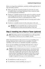
... not installing your Storage Enclosure into a rack or tower, skip to further reduce the weight, if required. Step 2: Installing into the bottom of tips and safety cautions: ■ Make sure that the mounting hardware and tools are easily accessible before installing the enclosure in the rack or tower. (You can also remove the two APCs to Step 3: Installing the Drive...
... not installing your Storage Enclosure into a rack or tower, skip to further reduce the weight, if required. Step 2: Installing into the bottom of tips and safety cautions: ■ Make sure that the mounting hardware and tools are easily accessible before installing the enclosure in the rack or tower. (You can also remove the two APCs to Step 3: Installing the Drive...
User Guide
Page 27
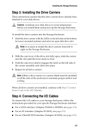
... Storage Enclosure Step 3: Installing the Drive Carriers These instructions assume that the drive carriers have already been attached to your specific Storage Enclosure interface: ■ For a SATA interface (Adaptec FS4100 or FS4500), see page 2-10. ■ For an FC interface (Adaptec FC4100), see page 2-11. ■ For an Ultra320 SCSI interface (Adaptec SC4100), see page 2-12. 2-9 Caution: Acclimate new disk drives to your Storage Enclosure, follow the instructions...
... Storage Enclosure Step 3: Installing the Drive Carriers These instructions assume that the drive carriers have already been attached to your specific Storage Enclosure interface: ■ For a SATA interface (Adaptec FS4100 or FS4500), see page 2-10. ■ For an FC interface (Adaptec FC4100), see page 2-11. ■ For an Ultra320 SCSI interface (Adaptec SC4100), see page 2-12. 2-9 Caution: Acclimate new disk drives to your Storage Enclosure, follow the instructions...
User Guide
Page 31
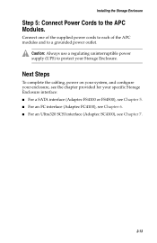
... FS4500), see Chapter 5. ■ For an FC interface (Adaptec FC4100), see Chapter 6. ■ For an Ultra320 SCSI interface (Adaptec SC4100), see Chapter 7. 2-13 Connect one of the supplied power cords to each of the APC modules and to the APC Modules. Next Steps To complete the cabling, power on your system, and configure your enclosure, see the chapter provided for your Storage Enclosure. Installing the Storage Enclosure...
... FS4500), see Chapter 5. ■ For an FC interface (Adaptec FC4100), see Chapter 6. ■ For an Ultra320 SCSI interface (Adaptec SC4100), see Chapter 7. 2-13 Connect one of the supplied power cords to each of the APC modules and to the APC Modules. Next Steps To complete the cabling, power on your system, and configure your enclosure, see the chapter provided for your Storage Enclosure. Installing the Storage Enclosure...
User Guide
Page 33
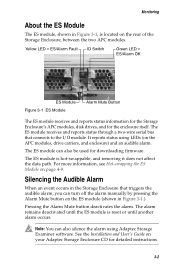
... not affect the data path. See the Installation and User's Guide on page 4-9. Yellow LED = ES/Alarm Fault ID Switch Green LED = ES/Alarm OK ES Module Figure 3-1 ES Module Alarm Mute Button The ES module receives and reports status information for the Storage Enclosure's APC modules, disk drives, and for detailed instructions. 3-2 The ES module can also be used for downloading firmware. The ES module is reset or until another...
... not affect the data path. See the Installation and User's Guide on page 4-9. Yellow LED = ES/Alarm Fault ID Switch Green LED = ES/Alarm OK ES Module Figure 3-1 ES Module Alarm Mute Button The ES module receives and reports status information for the Storage Enclosure's APC modules, disk drives, and for detailed instructions. 3-2 The ES module can also be used for downloading firmware. The ES module is reset or until another...
User Guide
Page 54
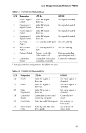
... 5-5 FS4500 I /O activity 7a Partner Failed Partner controller failure detected Partner controller operating normally 8 Controller Ready Controller active and Controller not ready operating normally a In single controller configurations, this LED is active and operating properly Controller not ready D5 Host Ports Activity on FC Host ports No activity on host ports D6 SATA Drive Activity on SATA disk Ports drive ports No activity on drive ports 5-7 SATA Storage Enclosures (FS4100 and FS4500) Table 5-4 FS4100 I/O Module LEDs LED Designation LED On LED...
... 5-5 FS4500 I /O activity 7a Partner Failed Partner controller failure detected Partner controller operating normally 8 Controller Ready Controller active and Controller not ready operating normally a In single controller configurations, this LED is active and operating properly Controller not ready D5 Host Ports Activity on FC Host ports No activity on host ports D6 SATA Drive Activity on SATA disk Ports drive ports No activity on drive ports 5-7 SATA Storage Enclosures (FS4100 and FS4500) Table 5-4 FS4100 I/O Module LEDs LED Designation LED On LED...
User Guide
Page 55
...FS4100 I/O Module Configuration The Adaptec FS4100 I /O Module LEDs LED Designation D7a Partner Failed LED On Partner controller has failed D8-1 Cache/BBU Fault ■ Data in cache memory ■ Cache memory failed ■ Cache being held by battery back-up is not used. SATA Storage Enclosures (FS4100 and FS4500) Table 5-5 FS4500 I /O module supports JBOD and does not require configuring. LED Off Partner controller operating properly Battery back-up ■ Battery not capable of sustaining memory ■ Battery not present a In single controller configurations, this LED is...
...FS4100 I/O Module Configuration The Adaptec FS4100 I /O Module LEDs LED Designation D7a Partner Failed LED On Partner controller has failed D8-1 Cache/BBU Fault ■ Data in cache memory ■ Cache memory failed ■ Cache being held by battery back-up is not used. SATA Storage Enclosures (FS4100 and FS4500) Table 5-5 FS4500 I /O module supports JBOD and does not require configuring. LED Off Partner controller operating properly Battery back-up ■ Battery not capable of sustaining memory ■ Battery not present a In single controller configurations, this LED is...
User Guide
Page 62
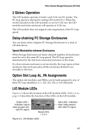
... 6-8 describes the function of 120 disk drives. Daisy-chaining FC Storage Enclosures You can be set for 2 Gb/sec, the LIO module and entire enclosure will operate at that enclosure; Option Slot Loop AL_PA Assignments The option slot modules and HBAs can daisy-chain Adaptec FC Storage Enclosures to the same FC loop speed. Output LED- Fibre Channel Storage Enclosures (FC4100) 2 Gb/sec Operation The...
... 6-8 describes the function of 120 disk drives. Daisy-chaining FC Storage Enclosures You can be set for 2 Gb/sec, the LIO module and entire enclosure will operate at that enclosure; Option Slot Loop AL_PA Assignments The option slot modules and HBAs can daisy-chain Adaptec FC Storage Enclosures to the same FC loop speed. Output LED- Fibre Channel Storage Enclosures (FC4100) 2 Gb/sec Operation The...
User Guide
Page 68
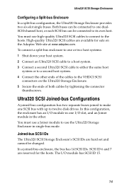
... disk drives. The I /O slot, and an Joiner module in single-bus mode. Joined-bus SCSI IDs The Ultra320 SCSI Storage Enclosure's SCSI IDs are hard set and cannot be connected to one I /O module has SCSI ID 15. 7-5 SCSI ID 6 and 7 are available for the hosts. To connect a split-bus enclosure to its own host. Ultra320 SCSI Storage Enclosures Configuring a Split-bus Enclosure In a split-bus configuration...
... disk drives. The I /O slot, and an Joiner module in single-bus mode. Joined-bus SCSI IDs The Ultra320 SCSI Storage Enclosure's SCSI IDs are hard set and cannot be connected to one I /O module has SCSI ID 15. 7-5 SCSI ID 6 and 7 are available for the hosts. To connect a split-bus enclosure to its own host. Ultra320 SCSI Storage Enclosures Configuring a Split-bus Enclosure In a split-bus configuration...
User Guide
Page 71
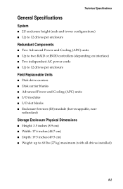
... two RAID or JBOD controllers (depending on interface) ■ Two independent AC power cords ■ Up to 60 lbs (27 kg) maximum (with all drives installed) 8-2 redundant) Storage Enclosure Physical Dimensions ■ Height: 3.5 inches (8.9 cm) ■ Width: 17.6 inches (44.7 cm) ■ Depth: 19.5 inches (49.5 cm) ■ Weight: up to 12 drives per enclosure Field Replaceable Units ■ Disk drive carriers ■ Disk carrier...
... two RAID or JBOD controllers (depending on interface) ■ Two independent AC power cords ■ Up to 60 lbs (27 kg) maximum (with all drives installed) 8-2 redundant) Storage Enclosure Physical Dimensions ■ Height: 3.5 inches (8.9 cm) ■ Width: 17.6 inches (44.7 cm) ■ Depth: 19.5 inches (49.5 cm) ■ Weight: up to 12 drives per enclosure Field Replaceable Units ■ Disk drive carriers ■ Disk carrier...
User Guide
Page 74
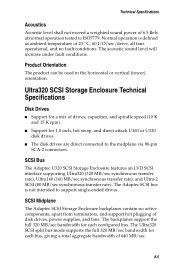
...). ■ Support for a mix of disk drives, power supplies, and fans. SCSI Midplane The Adaptec SCSI Storage Enclosure backplanes contain no fault conditions. Ultra320 SCSI Storage Enclosure Technical Specifications Disk Drives ■ Support for 1.0 inch, hot swap, and direct attach U160 or U320 disk drives. ■ The disk drives are direct connected to the midplane via 80-pin SCA-2 connectors. The backplanes support the full 320 MB/sec bandwidth for each configured bus...
...). ■ Support for a mix of disk drives, power supplies, and fans. SCSI Midplane The Adaptec SCSI Storage Enclosure backplanes contain no fault conditions. Ultra320 SCSI Storage Enclosure Technical Specifications Disk Drives ■ Support for 1.0 inch, hot swap, and direct attach U160 or U320 disk drives. ■ The disk drives are direct connected to the midplane via 80-pin SCA-2 connectors. The backplanes support the full 320 MB/sec bandwidth for each configured bus...
User Guide
Page 75
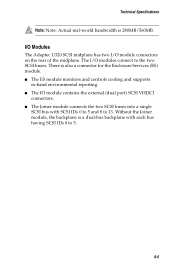
... the Enclosure Services (ES) module. ■ The ES module monitors and controls cooling and supports in-band environmental reporting. ■ The IO module contains the external (dual port) SCSI VHDCI connectors. ■ The Joiner module connects the two SCSI buses into a single SCSI bus with each bus having SCSI IDs 0 to 5. 8-6 The I /O module connectors on the rear of the midplane. I/O Modules The Adaptec...
... the Enclosure Services (ES) module. ■ The ES module monitors and controls cooling and supports in-band environmental reporting. ■ The IO module contains the external (dual port) SCSI VHDCI connectors. ■ The Joiner module connects the two SCSI buses into a single SCSI bus with each bus having SCSI IDs 0 to 5. 8-6 The I /O module connectors on the rear of the midplane. I/O Modules The Adaptec...
User Guide
Page 78
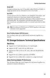
The redundant controller provides data access from one I /O modules, and connects to from more hosts and added security of disk drive vendors in the same enclosure is not supported. Note: Including an FS4100 and an FS4500 together in a single enclosure. FC Storage Enclosure Technical Specifications Disk Drives ■ Support for 3.5 inch disk drives of 1.0 inch height. ■ Support for FC 1 and 2 Gb/sec disk drives. ■ Support for 7200 (1 Gb/sec FC only), 10K...
The redundant controller provides data access from one I /O modules, and connects to from more hosts and added security of disk drive vendors in the same enclosure is not supported. Note: Including an FS4100 and an FS4500 together in a single enclosure. FC Storage Enclosure Technical Specifications Disk Drives ■ Support for 3.5 inch disk drives of 1.0 inch height. ■ Support for FC 1 and 2 Gb/sec disk drives. ■ Support for 7200 (1 Gb/sec FC only), 10K...
User Guide
Page 89
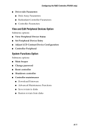
... RAID Controller (FS4500 only) ■ Drive-side Parameters ■ Disk Array Parameters ■ Redundant Controller Parameters ■ Controller Parameters View and Edit Peripheral Devices Option Submenu options: ■ View Peripheral Device Status ■ Set Peripheral Device Entry ■ Adjust LCD Contrast Device Configuration ■ Controller Peripheral System Functions Option Submenu options: ■ Mute beeper ■ Change password ■ Reset controller ■ Shutdown controller ■ Controller maintenance ■ Download Firmware...
... RAID Controller (FS4500 only) ■ Drive-side Parameters ■ Disk Array Parameters ■ Redundant Controller Parameters ■ Controller Parameters View and Edit Peripheral Devices Option Submenu options: ■ View Peripheral Device Status ■ Set Peripheral Device Entry ■ Adjust LCD Contrast Device Configuration ■ Controller Peripheral System Functions Option Submenu options: ■ Mute beeper ■ Change password ■ Reset controller ■ Shutdown controller ■ Controller maintenance ■ Download Firmware...