User Manual
Page 1
adaptec, inc. AHA-1540 User's Manual AT-to-SCSI Host Adapter
adaptec, inc. AHA-1540 User's Manual AT-to-SCSI Host Adapter
User Manual
Page 2
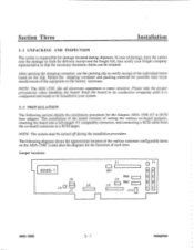
... can be initiated. Listed after the diagram are the functions of the individual items listed on -board connector to the factory necessary. Jumper locations: 8085-1 J6 J8 J5 J7 J1 LED J4 J9 RN6 RN7 J10 O F1 S S C C S S AHA-1540 3 - 1 adaptec Keep the board in its conductive wrapping until it is configured and ready to be turned off during shipment. Section Three Installation 3.1 UNPACKING AND...
... can be initiated. Listed after the diagram are the functions of the individual items listed on -board connector to the factory necessary. Jumper locations: 8085-1 J6 J8 J5 J7 J1 LED J4 J9 RN6 RN7 J10 O F1 S S C C S S AHA-1540 3 - 1 adaptec Keep the board in its conductive wrapping until it is configured and ready to be turned off during shipment. Section Three Installation 3.1 UNPACKING AND...

User Manual
Page 3
... last SCSI device in a string of SCSI devices, or if in-line terminators are the SCSI terminators. X 2 - -X 3 X X- 4 - The SCSI parity checking is disabled if this jumper is selected according to the following table. XX 1 X- If the AHA-1540 is parity checking enabled. 3.2.3 SCSI Terminators RN6 and RN7 are used, then both of pins. The SCSI address is installed. The SCSI address consists of pin pairs 4, 5, and 6 in the large block of jumper pins located...
... last SCSI device in a string of SCSI devices, or if in-line terminators are the SCSI terminators. X 2 - -X 3 X X- 4 - The SCSI parity checking is disabled if this jumper is selected according to the following table. XX 1 X- If the AHA-1540 is parity checking enabled. 3.2.3 SCSI Terminators RN6 and RN7 are used, then both of pins. The SCSI address is installed. The SCSI address consists of pin pairs 4, 5, and 6 in the large block of jumper pins located...

User Manual
Page 4
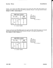
...SCSI bus. DMA Channel Jumpers Pin Pair DMA 7 8 Channel X X 0 - Pin pair 1 is jumper removed, synchronous negotiation initiation disabled. 3.3 AT CONFIGURATION 3.3.1 DMA Channel Selection There are Jl, J6, and J7. Default is the leftmost pair of pins. Pin pair 1 is the synchronous negotiation enable jumper. This jumper set J1, pin pair 1, is the left most pair of pins. These are three jumper blocks involved in selecting the DMA channel. X 5 X - 6 - - 7 X = Jumper Installed J1 7 8 0 0 0 0 0 0 0 X 0 0 0 0 0 0 0 0 0 0 X 0 0 0 pin pair 1 AHA-1540 3 - 3 adaptec...
...SCSI bus. DMA Channel Jumpers Pin Pair DMA 7 8 Channel X X 0 - Pin pair 1 is jumper removed, synchronous negotiation initiation disabled. 3.3 AT CONFIGURATION 3.3.1 DMA Channel Selection There are Jl, J6, and J7. Default is the leftmost pair of pins. Pin pair 1 is the synchronous negotiation enable jumper. This jumper set J1, pin pair 1, is the left most pair of pins. These are three jumper blocks involved in selecting the DMA channel. X 5 X - 6 - - 7 X = Jumper Installed J1 7 8 0 0 0 0 0 0 0 X 0 0 0 0 0 0 0 0 0 0 X 0 0 0 pin pair 1 AHA-1540 3 - 3 adaptec...
User Manual
Page 5
... corner of the small AT bus connector. Section Three Installation Jumper set J7 selects the DMA ACK signal to be used by the AHA-1540. This jumper set is the right most set J6 selects the DMA REQ signal to be used by the AHA-1540. DMA ACK Jumpers Pin Pair 4 3 - - - Pin Pair 4 3 21 X X X X DMA Channel 0 5 6 7 X = Jumper Installed J6 2 0 0 X 0 0 0 X 0 Pin Pair 1 AHA-1540 3 - 4 adaptec Pin Pair 1 Jumper set of pins. The default is DMA Acknowledge 5. Default is DMA Request 5.
... corner of the small AT bus connector. Section Three Installation Jumper set J7 selects the DMA ACK signal to be used by the AHA-1540. This jumper set is the right most set J6 selects the DMA REQ signal to be used by the AHA-1540. DMA ACK Jumpers Pin Pair 4 3 - - - Pin Pair 4 3 21 X X X X DMA Channel 0 5 6 7 X = Jumper Installed J6 2 0 0 X 0 0 0 X 0 Pin Pair 1 AHA-1540 3 - 4 adaptec Pin Pair 1 Jumper set of pins. The default is DMA Acknowledge 5. Default is DMA Request 5.
User Manual
Page 6
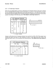
... bus connector. X - 11 X - - 10 - - - 9 x = Jumper Installed J1 9 10 11 0 0 0 0 0 0 0 0 0 X 0 0 0 0 0 0 0 0 0 0 X 0 pin pair 1 Jumper set by the AHA-1540. This jumper set according to the following table. AT Interrupt Channel Pin Pair Interrupt 9 10 11 Channel X X X Not Defined - X X Not Defined X - The interrupt channel reported to be used is interrupt channel 11. X 15 - - X 14 X X - 12 - Pin pair 1 is set J8 selects the AT interrupt channel to the AT during the Return Configuration Command...
... bus connector. X - 11 X - - 10 - - - 9 x = Jumper Installed J1 9 10 11 0 0 0 0 0 0 0 0 0 X 0 0 0 0 0 0 0 0 0 0 X 0 pin pair 1 Jumper set by the AHA-1540. This jumper set according to the following table. AT Interrupt Channel Pin Pair Interrupt 9 10 11 Channel X X X Not Defined - X X Not Defined X - The interrupt channel reported to be used is interrupt channel 11. X 15 - - X 14 X X - 12 - Pin pair 1 is set J8 selects the AT interrupt channel to the AT during the Return Configuration Command...
User Manual
Page 7
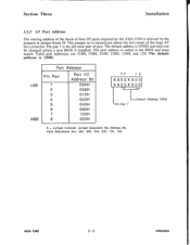
... AT bus connector. Valid Addresses Are: 334, 330, 234, 230, 134, 130 AHA-1540 3 - 6 adaptec This jumper set is located just above the left most pair of pins. The port address is 0330H and must match. The default address is coded in jumper block J9. LDefault Address 330H Pin Pair 1 X = Jumper Installed, Jumper Deasserts the Address Bit. The default address is supplied. LSB MSB Port Address Pin Pair 1 2 3 4 5 6 7 8 Port I /O ports required by the AHA-1540...
... AT bus connector. Valid Addresses Are: 334, 330, 234, 230, 134, 130 AHA-1540 3 - 6 adaptec This jumper set is located just above the left most pair of pins. The port address is 0330H and must match. The default address is coded in jumper block J9. LDefault Address 330H Pin Pair 1 X = Jumper Installed, Jumper Deasserts the Address Bit. The default address is supplied. LSB MSB Port Address Pin Pair 1 2 3 4 5 6 7 8 Port I /O ports required by the AHA-1540...

User Manual
Page 8
... been configured, the SCSI hard disk must also be re-formatted. The default address is no wait state. 3.3.6 Reserved Jumpers The jumper, pin pair 2 located in doubt on how your computer system shorts these address lines. X -- BIOS Address 0C8000H 0 D8000H 0CC000H 0DC000H J1 0 0 0 0 0 00 Pin Pair 1 X = Jumper Installed 3.3.5 AT BIOS Wait State Accesses to the Adaptec BIOS can have any other BIOS in the system. Contact your system manufacturer if in jumper block...
... been configured, the SCSI hard disk must also be re-formatted. The default address is no wait state. 3.3.6 Reserved Jumpers The jumper, pin pair 2 located in doubt on how your computer system shorts these address lines. X -- BIOS Address 0C8000H 0 D8000H 0CC000H 0DC000H J1 0 0 0 0 0 00 Pin Pair 1 X = Jumper Installed 3.3.5 AT BIOS Wait State Accesses to the Adaptec BIOS can have any other BIOS in the system. Contact your system manufacturer if in jumper block...


