Installation Guide
Page 2
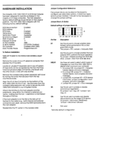
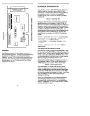
... Pin Pair DT BT MO MI SN DN R- Remove the corresponding system expansion slot cover by the target SCSI device. neg. Jumper Configuration Reference Five jumper blocks are used 'denotes default configuration Jumper Block J5 (Data) Default settings of AT class computers. Jumper MO, no jumper MI = Adaptec header display and error messages 2. on DN Use this AT slot. DMA Channel Interrupt Channel AT Port Address AT BIOS Address FD Controller Data Transfer Mode Enabled 7 Enabled Installed Supplying Enabled 0 11 340h DCOOOH, Enabled Enabled (AHA-1522) Programmed I /O Bus Connector...
... Pin Pair DT BT MO MI SN DN R- Remove the corresponding system expansion slot cover by the target SCSI device. neg. Jumper Configuration Reference Five jumper blocks are used 'denotes default configuration Jumper Block J5 (Data) Default settings of AT class computers. Jumper MO, no jumper MI = Adaptec header display and error messages 2. on DN Use this AT slot. DMA Channel Interrupt Channel AT Port Address AT BIOS Address FD Controller Data Transfer Mode Enabled 7 Enabled Installed Supplying Enabled 0 11 340h DCOOOH, Enabled Enabled (AHA-1522) Programmed I /O Bus Connector...
Installation Guide
Page 3
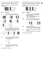
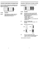
... pin pairs marked IC to support floppy drive with dual speed spindle. Use the four pin pairs marked DR and DA to select an IRQ channel. "No jumper= disabled; You must also use pin pairs 10, I1, 12, and 19 on the host adapter is supported. Jumper 10 = Interrupt Channel 10 enabled. O O DMA 0= O O DC DC Default SP Parity checking enabled or disabled. AHA-1522 Only The following diagram shows the default settings of jumper block J6: Pin...
... pin pairs marked IC to support floppy drive with dual speed spindle. Use the four pin pairs marked DR and DA to select an IRQ channel. "No jumper= disabled; You must also use pin pairs 10, I1, 12, and 19 on the host adapter is supported. Jumper 10 = Interrupt Channel 10 enabled. O O DMA 0= O O DC DC Default SP Parity checking enabled or disabled. AHA-1522 Only The following diagram shows the default settings of jumper block J6: Pin...
Installation Guide
Page 4
... host adapter BIOS enable. 'Jumper = Boot from SCSI disk disabled. 'denotes default configuration Jumper Block .18 (DMA Request & Acknowledge Channe0 Note that the DMA channel is also controller by jumper block J6. The other J8 jumper options are installed on }umber block J6. You must also select the corresponding interrupt channel with Windows 3.0) AL Select port address range. No jumper = 340-35E (hex); Jumper Block .19 (IRQ Channel, Port Address, and BIOS) The following diagram shows the default settings...
... host adapter BIOS enable. 'Jumper = Boot from SCSI disk disabled. 'denotes default configuration Jumper Block .18 (DMA Request & Acknowledge Channe0 Note that the DMA channel is also controller by jumper block J6. The other J8 jumper options are installed on }umber block J6. You must also select the corresponding interrupt channel with Windows 3.0) AL Select port address range. No jumper = 340-35E (hex); Jumper Block .19 (IRQ Channel, Port Address, and BIOS) The following diagram shows the default settings...
Installation Guide
Page 5
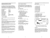
... drive C using the DOS COPY command. This saves any time without executing by pressing the ESC key. DOS provides access to partition and format the selected SCSI devices including removable media. SYS [ID] [ /R] 'Host adapter must be jumpered accordingly. The AFDISK utility also includes an on the SCSI Bus and has terminators installed at the factory. UOZZUJOI-OCCU) LUXI-LUCCZQ -I TERMINATORS INTERNAL SCSI HEADER AIC-6260AL DEFAULT SETTINGS AND REFERENCE DIAGRAM co w 0 w w I ] [/Z] DEVICE...
... drive C using the DOS COPY command. This saves any time without executing by pressing the ESC key. DOS provides access to partition and format the selected SCSI devices including removable media. SYS [ID] [ /R] 'Host adapter must be jumpered accordingly. The AFDISK utility also includes an on the SCSI Bus and has terminators installed at the factory. UOZZUJOI-OCCU) LUXI-LUCCZQ -I TERMINATORS INTERNAL SCSI HEADER AIC-6260AL DEFAULT SETTINGS AND REFERENCE DIAGRAM co w 0 w w I ] [/Z] DEVICE...
Installation Guide
Page 6
... a Class B computing device in accordance with the specifications in a particular installation. Questions can be answered via the Adaptec Bulletin Board (8 data bits, 1 stop bit, no guarantee that interference will not occur in 'Subpart J of Part 15 of the following booklet prepared by turning the equipment off and on different branch circuits. F.C.C. Relocate the computer with the manufacturer's instructions, may find the...
... a Class B computing device in accordance with the specifications in a particular installation. Questions can be answered via the Adaptec Bulletin Board (8 data bits, 1 stop bit, no guarantee that interference will not occur in 'Subpart J of Part 15 of the following booklet prepared by turning the equipment off and on different branch circuits. F.C.C. Relocate the computer with the manufacturer's instructions, may find the...
Installation Guide
Page 7
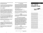
... of drive C using the MS-DOS COPY command. FAILURE TO LOAD ALL THE DEVICE DRIVERS IN THE CORRECT ORDER, CAUSES THE PROGRAM TO NOT BE INSTALLED. SOFTWARE INSTALLATION Copy the files from the ASW-1210 Program diskette to the User's Manual for the ASPI MS-DOS Manager files to be added to the device drivers in the MS-DOS Operations Reference Manual to create a new CONFIG.SYS file. In order for details.) DEVICE...
... of drive C using the MS-DOS COPY command. FAILURE TO LOAD ALL THE DEVICE DRIVERS IN THE CORRECT ORDER, CAUSES THE PROGRAM TO NOT BE INSTALLED. SOFTWARE INSTALLATION Copy the files from the ASW-1210 Program diskette to the User's Manual for the ASPI MS-DOS Manager files to be added to the device drivers in the MS-DOS Operations Reference Manual to create a new CONFIG.SYS file. In order for details.) DEVICE...
Installation Guide
Page 8
... SCSI cable must have terminators installed. Jumper Configuration Reference Five sets of jumpers are shown as shipped in the cable, remove the SCSI terminators from the corresponding expansion slot cover to secure the AHA-152X's bracket to ensure proper operation. DMA Channel Interrupt Channel AT Port Address AT BIOS Address FD Controller Data Transfer Mode Enabled 7 Disabled Installed Supplying Enabled 0 11 340h DCOOOH, Enabled Enabled (AHA-1522) PIO To Perform Installation: TURN OFF POWER TO THE SYSTEM AND EXTERNAL EQUIPMENT. If the host adapter...
... SCSI cable must have terminators installed. Jumper Configuration Reference Five sets of jumpers are shown as shipped in the cable, remove the SCSI terminators from the corresponding expansion slot cover to secure the AHA-152X's bracket to ensure proper operation. DMA Channel Interrupt Channel AT Port Address AT BIOS Address FD Controller Data Transfer Mode Enabled 7 Disabled Installed Supplying Enabled 0 11 340h DCOOOH, Enabled Enabled (AHA-1522) PIO To Perform Installation: TURN OFF POWER TO THE SYSTEM AND EXTERNAL EQUIPMENT. If the host adapter...


