
User Guide
Page 1
Table of Contents Precautions ...2 Special notes on LCD monitors 2 Package contents 3 Installation instructions 3 Assembling the monitor 3 Adjusting the viewing angle 4 Connecting the devices 5 Switching the power 6 Adjusting display settings 6 External controls 6 OSD options...7 OSD menu ...7 Troubleshooting 10 General specifications 11 1
Table of Contents Precautions ...2 Special notes on LCD monitors 2 Package contents 3 Installation instructions 3 Assembling the monitor 3 Adjusting the viewing angle 4 Connecting the devices 5 Switching the power 6 Adjusting display settings 6 External controls 6 OSD options...7 OSD menu ...7 Troubleshooting 10 General specifications 11 1
User Guide
Page 2
... be damaged if placed too near the screen. y Do not allow sharp objects such as the monitor requires ventilation. Recycling information Acer cares very much about /sustainability.htm United States: http://www.ciwmb.ca.gov/electronics/act2003/Recovery/Approved/ Asia: http://recycle.epa.gov.tw/public/public4_2....
... be damaged if placed too near the screen. y Do not allow sharp objects such as the monitor requires ventilation. Recycling information Acer cares very much about /sustainability.htm United States: http://www.ciwmb.ca.gov/electronics/act2003/Recovery/Approved/ Asia: http://recycle.epa.gov.tw/public/public4_2....
User Guide
Page 3
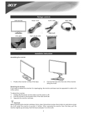
...make sure the power is off. 2. To detach the monitor: 1. Important When separating the monitor and base, find a clean, flat surface to protect it further. Detaching the monitor If you need to detach the monitor for repackaging, the monitor and base must be separated in the carton. After ...removing the monitor from the base, pull the monitor slightly up and away from the base and place it on...
...make sure the power is off. 2. To detach the monitor: 1. Important When separating the monitor and base, find a clean, flat surface to protect it further. Detaching the monitor If you need to detach the monitor for repackaging, the monitor and base must be separated in the carton. After ...removing the monitor from the base, pull the monitor slightly up and away from the base and place it on...

User Guide
Page 4
It may cause damage or break the LCD screen. • Careful attention is required not to catch your fingers or hands when you change the angle. 4 NOTES • Do not touch the LCD screen when you change the angle. Adjusting the viewing angle The viewing angle of the monitor ranges from -5 - 20°.
It may cause damage or break the LCD screen. • Careful attention is required not to catch your fingers or hands when you change the angle. 4 NOTES • Do not touch the LCD screen when you change the angle. Adjusting the viewing angle The viewing angle of the monitor ranges from -5 - 20°.

User Guide
Page 5
...DVI-D 5 WARNING! Check the VGA card of the graphics card on the computer. Connect the signal cable to the VGA input socket of the monitor, and connect the 2 VGA cable signal cable to the VGA output socket of your computer. Make sure the shape of the plug matches the shape...tighten the thumbscrews on the computer. Then tighten the thumbscrews on the connector. 4 Audio cable Connect the audio input socket (AUDIO IN) of the LCD monitor and the computer (Optional) by means of the graphics card on the connector. 3 DVI-D cable (Optional) Connect the signal cable to the DVI-D ...
...DVI-D 5 WARNING! Check the VGA card of the graphics card on the computer. Connect the signal cable to the VGA input socket of the monitor, and connect the 2 VGA cable signal cable to the VGA output socket of your computer. Make sure the shape of the plug matches the shape...tighten the thumbscrews on the computer. Then tighten the thumbscrews on the connector. 4 Audio cable Connect the audio input socket (AUDIO IN) of the LCD monitor and the computer (Optional) by means of the graphics card on the connector. 3 DVI-D cable (Optional) Connect the signal cable to the DVI-D ...

User Guide
Page 6
... is active, press Auto to exit a selection in sleep mode 6 If the OSD is inactive, press Auto and the monitor will automatically optimize the position, focus, and clock of monitor, then turn on PC and power button on Orange: in the OSD. Press again to toggle between the OSD options.... When you do not see the LED on the power button or a video signal, check the connections. Power on/off 5 Power Green: power on monitor's control panel. Adjusting display settings External controls 1 Auto If the OSD is ready for the video signal to view the OSD. Switching the power First...
... is active, press Auto to exit a selection in sleep mode 6 If the OSD is inactive, press Auto and the monitor will automatically optimize the position, focus, and clock of monitor, then turn on PC and power button on Orange: in the OSD. Press again to toggle between the OSD options.... When you do not see the LED on the power button or a video signal, check the connections. Power on/off 5 Power Green: power on monitor's control panel. Adjusting display settings External controls 1 Auto If the OSD is ready for the video signal to view the OSD. Switching the power First...
User Guide
Page 10
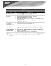
.... See horizontal and vertical position adjustment (p. 7). Check to adjust RGB color. Please refer all servicing to the back of the monitor and the computer. Inspect the monitor's video cable and ensure that the Power Cord is connected. Ensure that none of the pins are bent. Ensure the video cable... bounces or a y wave pattern is y present in the picture Image is not sized or y centered properly y Possible Solutions Check to bring the monitor out of "active off electrical devices that the power cord is connected. Move the mouse or press any key on the keyboard to see if...
.... See horizontal and vertical position adjustment (p. 7). Check to adjust RGB color. Please refer all servicing to the back of the monitor and the computer. Inspect the monitor's video cable and ensure that the Power Cord is connected. Ensure that none of the pins are bent. Ensure the video cable... bounces or a y wave pattern is y present in the picture Image is not sized or y centered properly y Possible Solutions Check to bring the monitor out of "active off electrical devices that the power cord is connected. Move the mouse or press any key on the keyboard to see if...
Service Guide
Page 5
... the equipment and receiver. 3. As an ENERGY STAR® Partner our company has determined that this equipment. These limits are present inside the monitor. This equipment generates, uses and can be used in a particular installation. WARNING: To prevent fire or chock hazard, do not expose the... monitor to qualified personnel only. - 5 - It is the responsibility of the user to which the receiver is not responsible for help. Consult the dealer ...
... the equipment and receiver. 3. As an ENERGY STAR® Partner our company has determined that this equipment. These limits are present inside the monitor. This equipment generates, uses and can be used in a particular installation. WARNING: To prevent fire or chock hazard, do not expose the... monitor to qualified personnel only. - 5 - It is the responsibility of the user to which the receiver is not responsible for help. Consult the dealer ...
Service Guide
Page 6
...kit instructions. z Slots and openings in a bookcase or cabinet unless proper ventilation is equipped with a three-pronged grounded plug, a plug with the monitor. This plug will fit only into the slot on a wall or shelf, use an adapter to power surges. Please refer all servicing to service ... and shall be installed near or over a radiator or heat register. z Unplug the unit during a lightning storm or when it will protect the monitor from damage due to ground the appliance safely. z Do not overload power strips and extension cords. Never spill liquids on a bed, sofa, rug...
...kit instructions. z Slots and openings in a bookcase or cabinet unless proper ventilation is equipped with a three-pronged grounded plug, a plug with the monitor. This plug will fit only into the slot on a wall or shelf, use an adapter to power surges. Please refer all servicing to service ... and shall be installed near or over a radiator or heat register. z Unplug the unit during a lightning storm or when it will protect the monitor from damage due to ground the appliance safely. z Do not overload power strips and extension cords. Never spill liquids on a bed, sofa, rug...

Service Guide
Page 7
... screen may include blemishes of 0.01% or less such as a missing pixel or a pixel lit all of 99.99% or more. SPECIAL NOTES ON LCD MONITORS The following symptoms are normal with LCD...
... screen may include blemishes of 0.01% or less such as a missing pixel or a pixel lit all of 99.99% or more. SPECIAL NOTES ON LCD MONITORS The following symptoms are normal with LCD...
Service Guide
Page 8
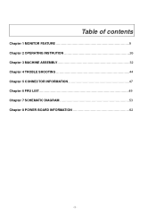
Table of contents Chapter 1 MONITOR FEATURE 9 Chapter 2 OPERATING INSTRUTION 26 Chapter 3 MACHINE ASSEMBLY 32 Chapter 4 TROBLE SHOOTING 44 Chapter 5 CONNECTOR INFORMATION 47 Chapter 6 FRU LIST 49 Chapter 7 SCHEMATIC DIAGRAM 53 Chapter 8 POWER BOARD INFORMATION 62 - 8 -
Table of contents Chapter 1 MONITOR FEATURE 9 Chapter 2 OPERATING INSTRUTION 26 Chapter 3 MACHINE ASSEMBLY 32 Chapter 4 TROBLE SHOOTING 44 Chapter 5 CONNECTOR INFORMATION 47 Chapter 6 FRU LIST 49 Chapter 7 SCHEMATIC DIAGRAM 53 Chapter 8 POWER BOARD INFORMATION 62 - 8 -
Service Guide
Page 9
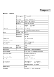
Chapter 1 Monitor Feature LCD Panel Input Display Color Maximum Dot Clock ® Max Resolution Plug & Play EPA ENERGY STAY Audio output Input Connector Input Video Signal Screen ...
Chapter 1 Monitor Feature LCD Panel Input Display Color Maximum Dot Clock ® Max Resolution Plug & Play EPA ENERGY STAY Audio output Input Connector Input Video Signal Screen ...

Service Guide
Page 26
... Panel Definition This Section defines the front panel User Interface for Led Indictor and Key function. If OSD is ○5 AUTO inactive, press and the monitor will automatically optimize the position, focus and clock of your display. - 26 -
... Panel Definition This Section defines the front panel User Interface for Led Indictor and Key function. If OSD is ○5 AUTO inactive, press and the monitor will automatically optimize the position, focus and clock of your display. - 26 -
Service Guide
Page 29
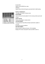
... memory address. Factory 2 Adjustment: This page only visible in factory mode AUTO BURN: Use the chip set internal frequency spread effect for hot running monitor panel and inverter. AUTO COLOR : Perform Auto Balance measurement . COLOR UPDATE: Force presently R,G,B offset and gain parameters update to factory setting and power...
... memory address. Factory 2 Adjustment: This page only visible in factory mode AUTO BURN: Use the chip set internal frequency spread effect for hot running monitor panel and inverter. AUTO COLOR : Perform Auto Balance measurement . COLOR UPDATE: Force presently R,G,B offset and gain parameters update to factory setting and power...

Service Guide
Page 30
HOW TO OPTIMIZE THE DOS-MODE Plug and play Plug & play DDC2B feature This monitor is equipped with VESA DDC2B capabilities according to indict system status and defined as bellows...System Status System in normal operation mode Amber System in power-saving mode Dark System in power-off mode LOGO: When the monitor is power on, the LOGO will be showed in two levels, DDC2B. The host can request EDID information over the ...equips one dual color (blue/amber) led to the VESA DDC STANDARD. It allows the monitor to inform the host system of its identity and, depending on the I2C protocol.
HOW TO OPTIMIZE THE DOS-MODE Plug and play Plug & play DDC2B feature This monitor is equipped with VESA DDC2B capabilities according to indict system status and defined as bellows...System Status System in normal operation mode Amber System in power-saving mode Dark System in power-off mode LOGO: When the monitor is power on, the LOGO will be showed in two levels, DDC2B. The host can request EDID information over the ...equips one dual color (blue/amber) led to the VESA DDC STANDARD. It allows the monitor to inform the host system of its identity and, depending on the I2C protocol.

Service Guide
Page 31
... supply consumption. The other end terminates with a grounding type attachment plug, rated 10A, 250V,CEE-22 male configuration. This monitor meets the Green monitor standards as set consisting of personal computer: Please use VDE 0602, 0625, 0821 approval power cord in European counties. - 31...Screen Saver" feature except the display is no video-input signal present. Supplied with NEMA 5-15 style and is no video input signal this monitor, following a time-out period, will automatically switch to conserve electrical energy by pressing a key on type connector body, rated 10A, 250V,...
... supply consumption. The other end terminates with a grounding type attachment plug, rated 10A, 250V,CEE-22 male configuration. This monitor meets the Green monitor standards as set consisting of personal computer: Please use VDE 0602, 0625, 0821 approval power cord in European counties. - 31...Screen Saver" feature except the display is no video-input signal present. Supplied with NEMA 5-15 style and is no video input signal this monitor, following a time-out period, will automatically switch to conserve electrical energy by pressing a key on type connector body, rated 10A, 250V,...

Service Guide
Page 32
Therefore, lay the monitor on how to scratching! Wear gloves. Front View: ( unit : inch ) - 32 - The screws for maintenance and trouble shooting NOTE : 1. Chapter 3 Machine assembly This chapter contains step-by-step procedures on a soft surface when mounting or removing the base. 3. Note : The monitor surface is susceptible to assemble the monitor for the different components vary in size. During the disassembly process, group the screws with the corresponding to avoid mismatch when putting back the components. 2.
Therefore, lay the monitor on how to scratching! Wear gloves. Front View: ( unit : inch ) - 32 - The screws for maintenance and trouble shooting NOTE : 1. Chapter 3 Machine assembly This chapter contains step-by-step procedures on a soft surface when mounting or removing the base. 3. Note : The monitor surface is susceptible to assemble the monitor for the different components vary in size. During the disassembly process, group the screws with the corresponding to avoid mismatch when putting back the components. 2.


