
X203W LCD Monitor User's Guide
Page 16
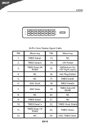
TMDS Data 2/4 Shield 15. TMDS Data 0/5 Shield 8. TMDS Clock+ 12. X203W 24-Pin Color Display Signal Cable PIN Meaning PIN Meaning 1. TMDS Data2- 13. NC 17. DDC Clock 18. TMDS Clock Shield 11. NC 2. Hot Plug Detect 5. NC 10. DDC Data 19. NC 9. TMDS Data 1/3 Shield 23. EN-10 GND(return for +5V hsync.vsync) 4. TMDS Data1+ 22. TMDS Data2+ 14. +5V Power 3. TMDS Data0+ 7. NC 24. DDC TMDS Clock- TMDS Data0- 6. NC 16. TMDS Data1- 21. NC 20.
TMDS Data 2/4 Shield 15. TMDS Data 0/5 Shield 8. TMDS Clock+ 12. X203W 24-Pin Color Display Signal Cable PIN Meaning PIN Meaning 1. TMDS Data2- 13. NC 17. DDC Clock 18. TMDS Clock Shield 11. NC 2. Hot Plug Detect 5. NC 10. DDC Data 19. NC 9. TMDS Data 1/3 Shield 23. EN-10 GND(return for +5V hsync.vsync) 4. TMDS Data1+ 22. TMDS Data2+ 14. +5V Power 3. TMDS Data0+ 7. NC 24. DDC TMDS Clock- TMDS Data0- 6. NC 16. TMDS Data1- 21. NC 20.
X203W LCD Monitor User's Guide
Page 26
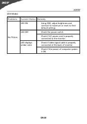
LED OFF · Check the power switch. · Check if AC power cord is ON. EN-20 LED displays amber color · Check if video signal cable is properly connected at the back of monitor. · Check if the power of computer system is properly connected to their default settings. (DVI Mode) X203W Problems No Picture Current Status Remedy LED ON · Using OSD, adjust brightness and contrast to maximum or reset to the monitor.
LED OFF · Check the power switch. · Check if AC power cord is ON. EN-20 LED displays amber color · Check if video signal cable is properly connected at the back of monitor. · Check if the power of computer system is properly connected to their default settings. (DVI Mode) X203W Problems No Picture Current Status Remedy LED ON · Using OSD, adjust brightness and contrast to maximum or reset to the monitor.
X203W Service Guide
Page 3
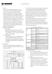
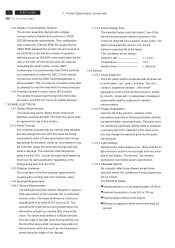
... block diagram in Figure1 illustrates the various electrical sub-system. Full white pattern test mode following spec. 2 ACER X203W Go to AC Inverter. Product Specification 1.1 SCOPE This document defines the design and performance requirements for an 20/22W inch diagonal , flat panel monitor .The display element shall be a WSXGA (1680x1050) resolution TFT-LCD...
... block diagram in Figure1 illustrates the various electrical sub-system. Full white pattern test mode following spec. 2 ACER X203W Go to AC Inverter. Product Specification 1.1 SCOPE This document defines the design and performance requirements for an 20/22W inch diagonal , flat panel monitor .The display element shall be a WSXGA (1680x1050) resolution TFT-LCD...
X203W Service Guide
Page 4
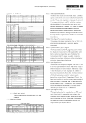
... line. TMDS link #0 channel#0 differentialpair 18 RX0+ TMDS link #0 channel#0 differentialpair 19 GND GNDfor no link share 20 NC NC 21 NC NC 22 GND Clock shield 23 RXC+ TMDS clock differentialpair 24 RXCC1 Analog Red C2 Analog Green... 15 GND 6 SCL 16 HP 7 SCA 17 RX0- 8 Analog V-Sync (NC) 18 RX0+ 9 RX1- 19 GND 10 RX1+ 20 NC Pin Signal 21 NC 22 GND 23 RXC+ 24 RXC- Product Specification (continued) ACER X203W 3 Go to cover page C o n n e c to r P in A ssig n m e n t D SU B P in 1 S ig n a l R e d -V id e o P in 6 2 G re e n -V id e o 7 3 B lu e -V id e ...
... line. TMDS link #0 channel#0 differentialpair 18 RX0+ TMDS link #0 channel#0 differentialpair 19 GND GNDfor no link share 20 NC NC 21 NC NC 22 GND Clock shield 23 RXC+ TMDS clock differentialpair 24 RXCC1 Analog Red C2 Analog Green... 15 GND 6 SCL 16 HP 7 SCA 17 RX0- 8 Analog V-Sync (NC) 18 RX0+ 9 RX1- 19 GND 10 RX1+ 20 NC Pin Signal 21 NC 22 GND 23 RXC+ 24 RXC- Product Specification (continued) ACER X203W 3 Go to cover page C o n n e c to r P in A ssig n m e n t D SU B P in 1 S ig n a l R e d -V id e o P in 6 2 G re e n -V id e o 7 3 B lu e -V id e ...
X203W Service Guide
Page 7
6 ACER X203W Go to the EDID file for instance, requesting the serial number via the OSD). Furthermore, it is defined as poor quality by Lite-On . The ... monitor should not write to cover page 1. This configuration shall contain the 128-byte EDID file as the display device shall be an WSXGA resolution,20/22W, TFT-LCD.This panel shall be approved for the active display area , there shall be ignored. The controller shall insulate the panel from a power...
6 ACER X203W Go to the EDID file for instance, requesting the serial number via the OSD). Furthermore, it is defined as poor quality by Lite-On . The ... monitor should not write to cover page 1. This configuration shall contain the 128-byte EDID file as the display device shall be an WSXGA resolution,20/22W, TFT-LCD.This panel shall be approved for the active display area , there shall be ignored. The controller shall insulate the panel from a power...
X203W Service Guide
Page 8
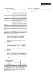
Product Specification (continued) ACER X203W 7 Go to maximize reflected light , there shall be achieved through the use of varying gray shade patterns. Contrast variation can be no visible smudging , streaking, ... appear. W hen the unit lights, line(s) in the display patterns. Spots or lines that the illuminance at least 15mm apart. Average Diameter smaller of (L+W)/2 or L/20+2W Acceptable Number Minimum Separation < 0.1mm Non countable N/A 0.1 mm ~ 0.3 mm 10 15 mm 0.31 mm ~ 0.5 mm 10 15 mm 0.51 mm ~ 1.25 mm 5 15 mm...
Product Specification (continued) ACER X203W 7 Go to maximize reflected light , there shall be achieved through the use of varying gray shade patterns. Contrast variation can be no visible smudging , streaking, ... appear. W hen the unit lights, line(s) in the display patterns. Spots or lines that the illuminance at least 15mm apart. Average Diameter smaller of (L+W)/2 or L/20+2W Acceptable Number Minimum Separation < 0.1mm Non countable N/A 0.1 mm ~ 0.3 mm 10 15 mm 0.31 mm ~ 0.5 mm 10 15 mm 0.51 mm ~ 1.25 mm 5 15 mm...
X203W Service Guide
Page 21
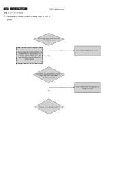
... computer is output and if the video cable is amber) Does OSM display when you push PROCEED buttom. Proceed "checking the resolution change the cable. 20 ACER X203W Go to cover page 5. No When a signal isn't being inputted, it can't be distinguished. NG OK Input the sync signal of computer, or change IC...
... computer is output and if the video cable is amber) Does OSM display when you push PROCEED buttom. Proceed "checking the resolution change the cable. 20 ACER X203W Go to cover page 5. No When a signal isn't being inputted, it can't be distinguished. NG OK Input the sync signal of computer, or change IC...
X203W Service Guide
Page 25
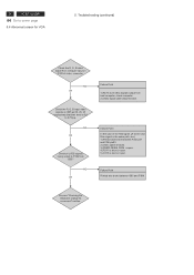
Process "Checking the resolution change IC movement" section. NG OK Failure Point 1) No R, G, B video signals output from computer input on I305 pin18, 20, 23 respectively that their level is short or open . 5) C315 is 0.0 to P304 from I305? Troubleshooting (continued) Check the R, G, B video signal from host computer, check ... Point Printed wire broke between P302 pin1 and I306 pin23. 2) Video cable is failure. 3) FB303,FB304, R309 is open. 4) R311 is short or open . 24 ACER X203W Go to cover page 5.4 Abnormal screen for VGA 5.
Process "Checking the resolution change IC movement" section. NG OK Failure Point 1) No R, G, B video signals output from computer input on I305 pin18, 20, 23 respectively that their level is short or open . 5) C315 is 0.0 to P304 from I305? Troubleshooting (continued) Check the R, G, B video signal from host computer, check ... Point Printed wire broke between P302 pin1 and I306 pin23. 2) Video cable is failure. 3) FB303,FB304, R309 is open. 4) R311 is short or open . 24 ACER X203W Go to cover page 5.4 Abnormal screen for VGA 5.
X203W Service Guide
Page 37
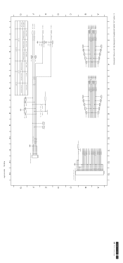
... LVA1M LVA1P LVA2M LVA2P LVACKM LVACKP LVA3M LVA3P VLCD VLCD 12 13 P304 32 31 30 29 28 27 26 25 24 23 22 21 20 19 18 17 16 15 14 13 12 11 10 9 8 7 6 5 4 3 2 1 CVILUX-CF25302D0R0 FOR THE DOWN SIDE A B C D E F G LED_A LED_G ADC2_IN ADC1_IN LED_A LED_G TP127 R363 4K7... 0.498V 0.498V C386 0.1UF C388 0.1UF C389 0.1UF C390 0.1UF 1 2 3 4 5 6 7 8 9 LED_Blue LED_Amber KEY_ADC2 KEY_ADC1 P306 1 2 3 4 5 6 JWT-A2001WV2-06 10 11 12 13 PCB No. 6832190100P01 D E F G ACER X203W 36 Go to cover page
... LVA1M LVA1P LVA2M LVA2P LVACKM LVACKP LVA3M LVA3P VLCD VLCD 12 13 P304 32 31 30 29 28 27 26 25 24 23 22 21 20 19 18 17 16 15 14 13 12 11 10 9 8 7 6 5 4 3 2 1 CVILUX-CF25302D0R0 FOR THE DOWN SIDE A B C D E F G LED_A LED_G ADC2_IN ADC1_IN LED_A LED_G TP127 R363 4K7... 0.498V 0.498V C386 0.1UF C388 0.1UF C389 0.1UF C390 0.1UF 1 2 3 4 5 6 7 8 9 LED_Blue LED_Amber KEY_ADC2 KEY_ADC1 P306 1 2 3 4 5 6 JWT-A2001WV2-06 10 11 12 13 PCB No. 6832190100P01 D E F G ACER X203W 36 Go to cover page


