Aspire X1200 / X3200 Service Guide
Page 12
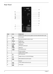
Rear Panel A Q B P C O D N E M E F G H L I K J Item A B C D E F G H I J K L M N O P Q Icon SPDIF ESATA HDMI Component Expansion slot (Photo shows graphics card and network/modem card) Line-out jack Microphone/speaker-out/line-in jack S/PDIF port USB 2.0 ports eSATA port CRT/LCD monitor port HDMI port PS2 keyboard port Power connector Voltage selector switch PS2 mouse port Gigabit LAN port (10/100/1000 Mbps) Rear speaker/surround out jack Keyhole Center speaker/subwoofer jack Line-in jack 4 Chapter 1
Rear Panel A Q B P C O D N E M E F G H L I K J Item A B C D E F G H I J K L M N O P Q Icon SPDIF ESATA HDMI Component Expansion slot (Photo shows graphics card and network/modem card) Line-out jack Microphone/speaker-out/line-in jack S/PDIF port USB 2.0 ports eSATA port CRT/LCD monitor port HDMI port PS2 keyboard port Power connector Voltage selector switch PS2 mouse port Gigabit LAN port (10/100/1000 Mbps) Rear speaker/surround out jack Keyhole Center speaker/subwoofer jack Line-in jack 4 Chapter 1
Aspire X1200 / X3200 Service Guide
Page 26
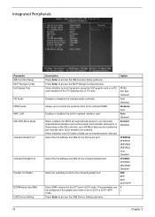
... for the first serial port. Press Enter to access the MCP Storage Config submenu. Allows you to boot the system using the AGP graphic card or a PCI card installed on the IDE controller, up to 64 KB of the onboard HDMI. This parameter can be transferred per interrupt when block transfers ...are enabled. Select DMA channel for the onboard parallel port. Select the I /O address and IRQ for the LPT port in network interface card. Select whether to control the audio function of data can be configured if the parallel port mode is set the proper block transfer settings for...
... for the first serial port. Press Enter to access the MCP Storage Config submenu. Allows you to boot the system using the AGP graphic card or a PCI card installed on the IDE controller, up to 64 KB of the onboard HDMI. This parameter can be transferred per interrupt when block transfers ...are enabled. Select DMA channel for the onboard parallel port. Select the I /O address and IRQ for the LPT port in network interface card. Select whether to control the audio function of data can be configured if the parallel port mode is set the proper block transfer settings for...
Aspire X1200 / X3200 Service Guide
Page 31
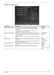
This parameter can be configured if the Resources Controlled By is automatically set to Manual. Enables or disables the system graphic card to auto ESCD, the system BIOS will update only when the new configuration varies from the last one. It allows you have to assign...and automatically assign the relative IRQ and DMA channel for Transaction packets (TLP). Set the maximum payload size for each system interrupt a type, depending on cards. When set to allow VGA palette snooping. Option Disabled Enabled Auto ESCD Manual IRQ-5 IRQ-7, IRQ-9, IRQ-10, IRQ-11, IRQ-14 Disabled ...
This parameter can be configured if the Resources Controlled By is automatically set to Manual. Enables or disables the system graphic card to auto ESCD, the system BIOS will update only when the new configuration varies from the last one. It allows you have to assign...and automatically assign the relative IRQ and DMA channel for Transaction packets (TLP). Set the maximum payload size for each system interrupt a type, depending on cards. When set to allow VGA palette snooping. Option Disabled Enabled Auto ESCD Manual IRQ-5 IRQ-7, IRQ-9, IRQ-10, IRQ-11, IRQ-14 Disabled ...
Aspire X1200 / X3200 Service Guide
Page 41
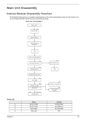
... ASSEMBLY CPU OPTICAL DISK DRIVE Ax1 HDD-ODD BRACKET Ax4 POWER SUPPLY Bx1 HDD MODULE HDD Screw List A B C D MEMORY MODULES Ax1 PCI CARD Bx2 FRONT I/O AND CARD READER BOARD BRACKET Dx2 Ax6, Cx1 MAINBOARD Screw #6-32 L5 BZN #6-32*3/16 NI M3xL5 BZN Hex screw Ax2 FRONT I/O BOARD Ax2... CARD READER BOARD Part No. 86.00J07.B60 86.5A5B6.012 86.1A324.5R0 N/A Chapter 3 33 Main Unit Disassembly External Modules Disassembly Flowchart The flowchart below gives you a graphic representation on the entire disassembly sequence and instructs you on the...
... ASSEMBLY CPU OPTICAL DISK DRIVE Ax1 HDD-ODD BRACKET Ax4 POWER SUPPLY Bx1 HDD MODULE HDD Screw List A B C D MEMORY MODULES Ax1 PCI CARD Bx2 FRONT I/O AND CARD READER BOARD BRACKET Dx2 Ax6, Cx1 MAINBOARD Screw #6-32 L5 BZN #6-32*3/16 NI M3xL5 BZN Hex screw Ax2 FRONT I/O BOARD Ax2... CARD READER BOARD Part No. 86.00J07.B60 86.5A5B6.012 86.1A324.5R0 N/A Chapter 3 33 Main Unit Disassembly External Modules Disassembly Flowchart The flowchart below gives you a graphic representation on the entire disassembly sequence and instructs you on the...


