Aspire M5620 Service Guide
Page 6
... Rear Panel 15 Hardware Specifications and Configurations 16 Power Management Function (ACPI support function 22 Chapter 2 System Utilities 23 Entering Setup 24 Product Information 26 Standard CMOS Features 27 Advanced BIOS Features 30 Integrated Peripherals 34 Power Management 41 PnP/PCI Configuration 44 PC Health Status 46 Frequency/Voltage Control 47 Load Default Settings 49 Set Supervisor/User Password 50 Save & Exit Setup 52 Exit Without Saving 53 Chapter 3 Machine Disassembly and Replacement 54 General Information 55 Disassembly...
... Rear Panel 15 Hardware Specifications and Configurations 16 Power Management Function (ACPI support function 22 Chapter 2 System Utilities 23 Entering Setup 24 Product Information 26 Standard CMOS Features 27 Advanced BIOS Features 30 Integrated Peripherals 34 Power Management 41 PnP/PCI Configuration 44 PC Health Status 46 Frequency/Voltage Control 47 Load Default Settings 49 Set Supervisor/User Password 50 Save & Exit Setup 52 Exit Without Saving 53 Chapter 3 Machine Disassembly and Replacement 54 General Information 55 Disassembly...
Aspire M5620 Service Guide
Page 19
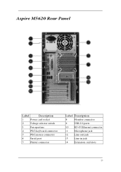
Aspire M5620 Rear Panel Label Description 1 Power card socket 2 Voltage selector switch 3 Fan aperture 4 PS/2 keyboard connector 5 PS/2 mouse connector 6 Serial port 7 Printer connector Label Description 8 Monitor connector 9 USB 2.0 ports 10 RJ-45 Ethernet connector 11 Microphone jack 12 Line-out jack 13 Line-in jack 14 Extension card slots 13
Aspire M5620 Rear Panel Label Description 1 Power card socket 2 Voltage selector switch 3 Fan aperture 4 PS/2 keyboard connector 5 PS/2 mouse connector 6 Serial port 7 Printer connector Label Description 8 Monitor connector 9 USB 2.0 ports 10 RJ-45 Ethernet connector 11 Microphone jack 12 Line-out jack 13 Line-in jack 14 Extension card slots 13
Aspire M5620 Service Guide
Page 21
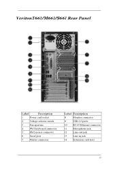
VeritonT661/M661/S661 Rear Panel Label Description 1 Power card socket 2 Voltage selector switch 3 Fan aperture 4 PS/2 keyboard connector 5 PS/2 mouse connector 6 Serial port 7 Printer connector Label Description 8 Monitor connector 9 USB 2.0 ports 10 RJ-45 Ethernet connector 11 Microphone jack 12 Line-out jack 13 Line-in jack 14 Extension card slots 15
VeritonT661/M661/S661 Rear Panel Label Description 1 Power card socket 2 Voltage selector switch 3 Fan aperture 4 PS/2 keyboard connector 5 PS/2 mouse connector 6 Serial port 7 Printer connector Label Description 8 Monitor connector 9 USB 2.0 ports 10 RJ-45 Ethernet connector 11 Microphone jack 12 Line-out jack 13 Line-in jack 14 Extension card slots 15
Aspire M5620 Service Guide
Page 22
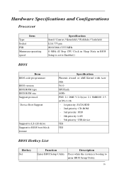
Hardware Specifications and Configurations Processor Item Type Socket FSB Minimum operating speed Specification Intel / Conroe / Kensfield / Wolfdale / Yorkfield LGA 775 pin 800/1066 /1333 MHz 0 MHz (If Stop CPU Clock in Sleep State in BIOS Setup is set to Enabled.) BIOS Item BIOS code programmer BIOS version BIOS ROM type BIOS ROM size Support protocol Device Boot Support Support to LS-120 drive Support to BIOS boot block feature Specification Phoenix Award or AMI Kernel with Acer skin V6.0 SPI Flash 16Mb PXE 2.1 DMI V.2.0(s)or 2.1 SMBIOS 2.5 ACPI...
Hardware Specifications and Configurations Processor Item Type Socket FSB Minimum operating speed Specification Intel / Conroe / Kensfield / Wolfdale / Yorkfield LGA 775 pin 800/1066 /1333 MHz 0 MHz (If Stop CPU Clock in Sleep State in BIOS Setup is set to Enabled.) BIOS Item BIOS code programmer BIOS version BIOS ROM type BIOS ROM size Support protocol Device Boot Support Support to LS-120 drive Support to BIOS boot block feature Specification Phoenix Award or AMI Kernel with Acer skin V6.0 SPI Flash 16Mb PXE 2.1 DMI V.2.0(s)or 2.1 SMBIOS 2.5 ACPI...
Aspire M5620 Service Guide
Page 26
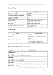
Serial Port Item Serial port controller Serial port controller resident bus Number of serial port 16550 UART support Connector type Optional serial port I/O address (via BIOS setup) Optional serial port IRQ (via BIOS setup) USB Port Specification ITE 8718 ISA bus 2 Yes 9-pin D-type female connector COM1: 2F8h, 3E8h, 2E8h COM2: 3E8h, 3F8h, 2F8h COM1: IRQ 3, and 4 COM2: IRQ 4, and 3 Universal HCI USB Class Item USB Connectors Quantity Specification USB 2.0 Support legacy keyboard for legacy mode 6 back panel ports 4 ports for front daughter board 2 ports for 3.5'' card reader module ...
Serial Port Item Serial port controller Serial port controller resident bus Number of serial port 16550 UART support Connector type Optional serial port I/O address (via BIOS setup) Optional serial port IRQ (via BIOS setup) USB Port Specification ITE 8718 ISA bus 2 Yes 9-pin D-type female connector COM1: 2F8h, 3E8h, 2E8h COM2: 3E8h, 3F8h, 2F8h COM1: IRQ 3, and 4 COM2: IRQ 4, and 3 Universal HCI USB Class Item USB Connectors Quantity Specification USB 2.0 Support legacy keyboard for legacy mode 6 back panel ports 4 ports for front daughter board 2 ports for 3.5'' card reader module ...
Aspire M5620 Service Guide
Page 35
... correct settings [Access Mode]: To set the access mode for detection options Channel X to select the situation if the BIOS stops the POST process and the notification All Errors No Errors All, But Keyboard All, But Diskette All, But Disk/Key 29 This is present during POST (default) IDE Master or Slave setup, press [None]: No IDE devices are : CHS/LBA/Large/Auto (default: Auto) Cylinder: Number of...
... correct settings [Access Mode]: To set the access mode for detection options Channel X to select the situation if the BIOS stops the POST process and the notification All Errors No Errors All, But Keyboard All, But Diskette All, But Disk/Key 29 This is present during POST (default) IDE Master or Slave setup, press [None]: No IDE devices are : CHS/LBA/Large/Auto (default: Auto) Cylinder: Number of...
Aspire M5620 Service Guide
Page 37
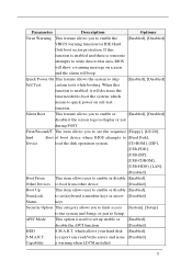
... [LS120], hird Boot of boot device where BIOS attempts to [Hard Disk], Device load the disk operation system. [CD-ROM], [ZIP], [USB-FDD], [USB-ZIP], [USB-CDROM], [USB-HDD], [LAN], [Disabled] Boot From This item allows user to enable or disable [Enabled], Other Devices to boot from other device [Disabled] Boot Up This item allows user to enable or disable [Enabled], NumLock to set up enable or [Enabled], disable the APCI function [Disabled] HDD S.M.A.R.T. Silent Boot This feature allows you to enable or [Enabled], [Disabled] disable if the screen logo to display or not...
... [LS120], hird Boot of boot device where BIOS attempts to [Hard Disk], Device load the disk operation system. [CD-ROM], [ZIP], [USB-FDD], [USB-ZIP], [USB-CDROM], [USB-HDD], [LAN], [Disabled] Boot From This item allows user to enable or disable [Enabled], Other Devices to boot from other device [Disabled] Boot Up This item allows user to enable or disable [Enabled], NumLock to set up enable or [Enabled], disable the APCI function [Disabled] HDD S.M.A.R.T. Silent Boot This feature allows you to enable or [Enabled], [Disabled] disable if the screen logo to display or not...
Aspire M5620 Service Guide
Page 42
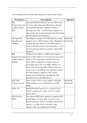
... IDE device (or IDE [Disabled] HDD) SATA 1/2 Enable/Disable Serial-ATA 1 or Serial-ATA-2. Parameter Description Options IDE The four IDE PIO fields let you install a primary and/or secondary add-in IDE interface. IDE Prefetch The onboard IDE drive interfaces supports IDE Mode prefetching, for two IDE channels. On-Chip IDE The Chipset contains a PCI IDE interface with [Enabled], First/Second support for faster drive accesses. SATA 1 control port 1 and 3, SATA 2 control port 2 and...
... IDE device (or IDE [Disabled] HDD) SATA 1/2 Enable/Disable Serial-ATA 1 or Serial-ATA-2. Parameter Description Options IDE The four IDE PIO fields let you install a primary and/or secondary add-in IDE interface. IDE Prefetch The onboard IDE drive interfaces supports IDE Mode prefetching, for two IDE channels. On-Chip IDE The Chipset contains a PCI IDE interface with [Enabled], First/Second support for faster drive accesses. SATA 1 control port 1 and 3, SATA 2 control port 2 and...
Aspire M5620 Service Guide
Page 44
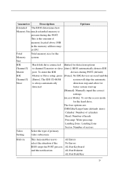
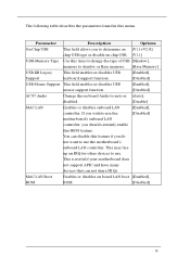
... or disables USB [Enabled], Support keyboard support function. [Disabled] USB Mouse Support This field enables or disables USB [Enabled], mouse support function. [Disabled] AC 97 Audio Change the on board LAN boot [Enabled], ROM ROM. [Disabled] 38 MAC LAN Boot Enables or disables on board Audio to auto or [Auto], disabled [Disable] MAC LAN Enables or disables onboard LAN [Enabled], controller, If you wish to use the [Disabled] motherboard's onboard LAN controller, you to determine on [V1.1+V2.0], chip USB type or disable on chip USB. [V1.1] UDB Memory Type Use this...
... or disables USB [Enabled], Support keyboard support function. [Disabled] USB Mouse Support This field enables or disables USB [Enabled], mouse support function. [Disabled] AC 97 Audio Change the on board LAN boot [Enabled], ROM ROM. [Disabled] 38 MAC LAN Boot Enables or disables on board Audio to auto or [Auto], disabled [Disable] MAC LAN Enables or disables onboard LAN [Enabled], controller, If you wish to use the [Disabled] motherboard's onboard LAN controller, you to determine on [V1.1+V2.0], chip USB type or disable on chip USB. [V1.1] UDB Memory Type Use this...

Aspire M5620 Service Guide
Page 46
Controller controller (FDC) installed on the system board [Disabled] and you install an add-in FDC or the system has no floppy drive, select Disabled in this field. Mode Full-duplex mode permits simultaneous tow-direction transmission. Half-duplex mode permits transmission in this field appears. UR2 Duplex In an infrared port mode, this menu. Select the value required by the IR device connected to manually set the DMA DMA...
Controller controller (FDC) installed on the system board [Disabled] and you install an add-in FDC or the system has no floppy drive, select Disabled in this field. Mode Full-duplex mode permits simultaneous tow-direction transmission. Half-duplex mode permits transmission in this field appears. UR2 Duplex In an infrared port mode, this menu. Select the value required by the IR device connected to manually set the DMA DMA...
Aspire M5620 Service Guide
Page 51
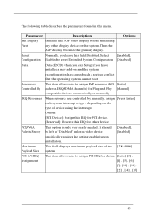
Parameter Description Options Init Display Initialize the AGP video display before initializing First any other device. Maximum This field displays maximum payload size of device using the interrupt. Option: [PCI Device]: Assign this IRQ for PCI device. [Reserved]: Reserve this field Disabled. PCI/VGA This option is only very rarely needed. Reset Normally, you have installed a new add-on and the system reconfiguration has caused such a serious conflict that the operating system cannot boot Resources...
Parameter Description Options Init Display Initialize the AGP video display before initializing First any other device. Maximum This field displays maximum payload size of device using the interrupt. Option: [PCI Device]: Assign this IRQ for PCI device. [Reserved]: Reserve this field Disabled. PCI/VGA This option is only very rarely needed. Reset Normally, you have installed a new add-on and the system reconfiguration has caused such a serious conflict that the operating system cannot boot Resources...

Veriton M661/T661/S661 Series User's Guide - EN
Page 8
... panel 2 Optical drive 3 Taking care of your CDs and DVDs 3 2 Setting up your computer 5 Arranging a comfortable work area 6 Positioning your monitor 6 Positioning your keyboard 6 Positioning your mouse 6 Connecting peripherals 6 Connecting your mouse and keyboard 7 USB interface 7 PS/2 interface 7 Connecting a monitor 7 Connecting the power cable 7 Turning on your computer 8 Turning off your computer 8 3 Upgrading your computer 9 Installation precautions 10 ESD precautions 10 Preinstallation instructions 10 Post-installation instructions 11 Opening...
... panel 2 Optical drive 3 Taking care of your CDs and DVDs 3 2 Setting up your computer 5 Arranging a comfortable work area 6 Positioning your monitor 6 Positioning your keyboard 6 Positioning your mouse 6 Connecting peripherals 6 Connecting your mouse and keyboard 7 USB interface 7 PS/2 interface 7 Connecting a monitor 7 Connecting the power cable 7 Turning on your computer 8 Turning off your computer 8 3 Upgrading your computer 9 Installation precautions 10 ESD precautions 10 Preinstallation instructions 10 Post-installation instructions 11 Opening...
Veriton M661/T661/S661 Series User's Guide - EN
Page 11
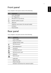
... English Front panel Your computer's front panel consists of the following: Icon Component 5.25" drive bay(s) 3.5" floppy drive Microphone-in jack (front) Speaker-out/line-out port USB ports Hardware reset button (for selected models) Indicators Power button Rear panel Your computer's rear panel consists of the following: Icon Component Power supply Power cord socket Voltage selector switch PS/2 mouse port PS/2 keyboard port Serial port Parallel/printer port CRT/LCD monitor port USB ports Network port Audio jack Expansion slots Chassis lock pad Hardware reset button (for selected...
... English Front panel Your computer's front panel consists of the following: Icon Component 5.25" drive bay(s) 3.5" floppy drive Microphone-in jack (front) Speaker-out/line-out port USB ports Hardware reset button (for selected models) Indicators Power button Rear panel Your computer's rear panel consists of the following: Icon Component Power supply Power cord socket Voltage selector switch PS/2 mouse port PS/2 keyboard port Serial port Parallel/printer port CRT/LCD monitor port USB ports Network port Audio jack Expansion slots Chassis lock pad Hardware reset button (for selected...
Veriton M661/T661/S661 Series User's Guide - EN
Page 16
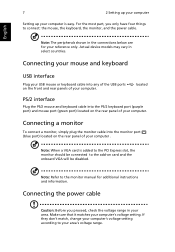
... power cable. Connecting your mouse and keyboard USB interface Plug your USB mouse or keyboard cable into the monitor port (blue port) located on card and the onboard VGA will be connected to the monitor manual for your area's voltage range. If they don't match, change your computer. For the most part, you proceed, check the voltage range in your computer . Make sure that it matches your computer is added to the PCI Express slot, the monitor...
... power cable. Connecting your mouse and keyboard USB interface Plug your USB mouse or keyboard cable into the monitor port (blue port) located on card and the onboard VGA will be connected to the monitor manual for your area's voltage range. If they don't match, change your computer. For the most part, you proceed, check the voltage range in your computer . Make sure that it matches your computer is added to the PCI Express slot, the monitor...
Veriton M661/T661/S661 Series User's Guide - EN
Page 19
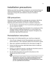
... preinstallation and post-installation instructions. Not turning off the computer properly before you install a computer component: 1 Do not remove a component from the power outlets. 2 Open your computer according to the instructions on page 10. 3 Follow the ESD precautions described above before handling a computer component. 4 Remove any component: 1 Turn off your processor, disk drives, expansion boards, and other components. Then unplug all cables from its protective...
... preinstallation and post-installation instructions. Not turning off the computer properly before you install a computer component: 1 Do not remove a component from the power outlets. 2 Open your computer according to the instructions on page 10. 3 Follow the ESD precautions described above before handling a computer component. 4 Remove any component: 1 Turn off your processor, disk drives, expansion boards, and other components. Then unplug all cables from its protective...
Veriton M661/T661/S661 Series User's Guide - EN
Page 20
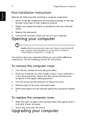
You need to open your computer in the regular desktop position. 3 Turn the screws counterclockwise to release the cover. 4 Hold the sides of the cover with the screws. If your computer is in their respective sections. 2 Replace any expansion boards or peripherals that you removed earlier. 3 Replace the side panels. 4 Connect the necessary cables and turn on page 10. English 11 3 Upgrading your computer Post-installation instructions Observe...
You need to open your computer in the regular desktop position. 3 Turn the screws counterclockwise to release the cover. 4 Hold the sides of the cover with the screws. If your computer is in their respective sections. 2 Replace any expansion boards or peripherals that you removed earlier. 3 Replace the side panels. 4 Connect the necessary cables and turn on page 10. English 11 3 Upgrading your computer Post-installation instructions Observe...

Veriton M661/T661/S661 Series User's Guide - EN
Page 22
13 3 Upgrading your computer's hard disk: 1 Remove the computer cover. 2 Detach all cables to view the new value for total system memory and make a note of memory installed. To reconfigure your computer Your computer automatically detects the amount of it. Set the drive rails aside. 4 Insert the new hard disk into the frame and secure it again. Replacing the hard disk Follow these steps to replace your computer 2 Align the DDR2...
13 3 Upgrading your computer's hard disk: 1 Remove the computer cover. 2 Detach all cables to view the new value for total system memory and make a note of memory installed. To reconfigure your computer Your computer automatically detects the amount of it. Set the drive rails aside. 4 Insert the new hard disk into the frame and secure it again. Replacing the hard disk Follow these steps to replace your computer 2 Align the DDR2...
Veriton M661/T661/S661 Series User's Guide - EN
Page 23
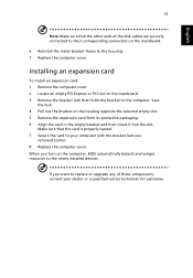
... installed devices. Make sure that the card is properly seated. 7 Secure the card to the computer. English 14 Note: Make sure that the other ends of these components, contact your computer with the bracket lock you turn on the computer, BIOS automatically detects and assigns resources to the housing. 7 Replace the computer cover. When you removed earlier. 8 Replace the computer cover. Installing an expansion card...
... installed devices. Make sure that the card is properly seated. 7 Secure the card to the computer. English 14 Note: Make sure that the other ends of these components, contact your computer with the bracket lock you turn on the computer, BIOS automatically detects and assigns resources to the housing. 7 Replace the computer cover. When you removed earlier. 8 Replace the computer cover. Installing an expansion card...
Veriton M661/T661/S661 Series User's Guide - EN
Page 26
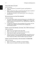
... drive by using the correct type of your dealer or technical support center for the Volume icon on . • Make sure the printer cable is clean and unscratched. • Check your USB keyboard to the lineout jack of disk or diskette. Do the following : • Make sure you are automatically turned off. System cannot read the information on . • If headphones, earphones or external speakers...
... drive by using the correct type of your dealer or technical support center for the Volume icon on . • Make sure the printer cable is clean and unscratched. • Check your USB keyboard to the lineout jack of disk or diskette. Do the following : • Make sure you are automatically turned off. System cannot read the information on . • If headphones, earphones or external speakers...
Veriton M661/T661/S661 Series User's Guide - EN
Page 31
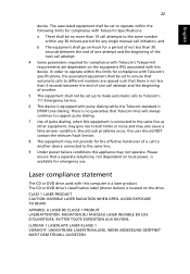
... not be set up to make automatic calls to different numbers are dependent on the drive. CLASS 1 LASER PRODUCT CAUTION: INVISIBLE LASER RADIATION WHEN OPEN. English English 22 device. The associated equipment shall be set to operate within the following limits for compliance with Telecom's Specifications: a There shall be no guarantee that a separate telephone, not dependent on local power, is...
... not be set up to make automatic calls to different numbers are dependent on the drive. CLASS 1 LASER PRODUCT CAUTION: INVISIBLE LASER RADIATION WHEN OPEN. English English 22 device. The associated equipment shall be set to operate within the following limits for compliance with Telecom's Specifications: a There shall be no guarantee that a separate telephone, not dependent on local power, is...


