
Generic User Guide
Page 3
... openings should be blocked or covered. If you are provided for ventilation to ensure reliable operation of power available, consult your safety and comfort Safety instructions Read these instructions carefully. Use a damp cloth for future reference. Never spill liquid of internal components and to prevent battery leakage, do not place the product on the product. Follow all products plugged into...
... openings should be blocked or covered. If you are provided for ventilation to ensure reliable operation of power available, consult your safety and comfort Safety instructions Read these instructions carefully. Use a damp cloth for future reference. Never spill liquid of internal components and to prevent battery leakage, do not place the product on the product. Follow all products plugged into...
Generic User Guide
Page 4
... restore the product to qualified service personnel when: • The power cord or plug is equipped with the supplied power supply cord set , make sure that are used, the load should not exceed 80% of the branch circuit rating. Note: Adjust only those controls that the new power cord meets the following the operating instructions. If power strips are covered by the operating instructions, since improper adjustment of other controls...
... restore the product to qualified service personnel when: • The power cord or plug is equipped with the supplied power supply cord set , make sure that are used, the load should not exceed 80% of the branch circuit rating. Note: Adjust only those controls that the new power cord meets the following the operating instructions. If power strips are covered by the operating instructions, since improper adjustment of other controls...

Generic User Guide
Page 5
... http://www.acer-group.com/public/Sustainability/sustainability04.htm Mercury advisory For projectors or electronic products containing an LCD/CRT monitor or display: Lamp(s) inside this electronic device into the trash when discarding. Replace only with the same or equivalent type recommended by the manufacturer. Dispose of used batteries according to this equipment during lightning or thunderstorms. Disposal instructions Do...
... http://www.acer-group.com/public/Sustainability/sustainability04.htm Mercury advisory For projectors or electronic products containing an LCD/CRT monitor or display: Lamp(s) inside this electronic device into the trash when discarding. Replace only with the same or equivalent type recommended by the manufacturer. Dispose of used batteries according to this equipment during lightning or thunderstorms. Disposal instructions Do...

Generic User Guide
Page 6
... and 30 minute of inactivity respectively. • Wake the computer from sleep mode by the U.S. Environmental Protection Agency. Acer ENERGY STAR qualified products: • Produce less heat and reduce cooling loads, and warmer climates. • Automatically go into "display sleep" and "computer sleep" mode after prolonged use Computer users may lead to Acer system with the ENERGY STAR mark. marks Tips...
... and 30 minute of inactivity respectively. • Wake the computer from sleep mode by the U.S. Environmental Protection Agency. Acer ENERGY STAR qualified products: • Produce less heat and reduce cooling loads, and warmer climates. • Automatically go into "display sleep" and "computer sleep" mode after prolonged use Computer users may lead to Acer system with the ENERGY STAR mark. marks Tips...
Generic User Guide
Page 7
...tensing your muscles or shrugging your shoulders. • Install the external display, keyboard and mouse properly and within comfortable reach. • If you have these symptoms, or any light source. • Minimizing room light by looking at the center of your sitting height to minimize neck strain. Eyes ...excessive room lighting, poorly focused screens, very small typefaces and low-contrast displays could stress your comfort zone by adjusting the viewing angle of the display so your eyes point downward when looking away from the monitor and focusing on how to computer use . ...
...tensing your muscles or shrugging your shoulders. • Install the external display, keyboard and mouse properly and within comfortable reach. • If you have these symptoms, or any light source. • Minimizing room light by looking at the center of your sitting height to minimize neck strain. Eyes ...excessive room lighting, poorly focused screens, very small typefaces and low-contrast displays could stress your comfort zone by adjusting the viewing angle of the display so your eyes point downward when looking away from the monitor and focusing on how to computer use . ...
Generic User Guide
Page 9
... optical discs 4 2 Setting up your computer 5 Arranging a comfortable work area 6 Positioning your monitor 6 Positioning your keyboard 6 Positioning your mouse 7 Connecting peripherals 7 Connecting your mouse and keyboard 7 USB interface 7 PS/2 interface 7 Connecting a monitor 7 Connecting the power cable 8 Turning on your computer 8 Turning off your computer 8 3 Upgrading your computer 9 Installation precautions 10 ESD precautions 10 Preinstallation instructions 10 Post-installation instructions 10 Opening your computer 11 To remove the computer cover...
... optical discs 4 2 Setting up your computer 5 Arranging a comfortable work area 6 Positioning your monitor 6 Positioning your keyboard 6 Positioning your mouse 7 Connecting peripherals 7 Connecting your mouse and keyboard 7 USB interface 7 PS/2 interface 7 Connecting a monitor 7 Connecting the power cable 8 Turning on your computer 8 Turning off your computer 8 3 Upgrading your computer 9 Installation precautions 10 ESD precautions 10 Preinstallation instructions 10 Post-installation instructions 10 Opening your computer 11 To remove the computer cover...
Generic User Guide
Page 12
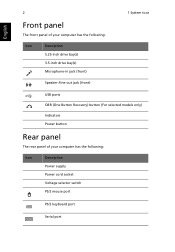
English 2 1 System tour Front panel The front panel of your computer has the following: Icon Description 5.25-inch drive bay(s) 3.5-inch drive bay(s) Microphone-in jack (front) Speaker-/line-out jack (front) USB ports OBR (One Button Recovery) button (For selected models only) Indicators Power button Rear panel The rear panel of your computer has the following: Icon Description Power supply Power cord socket Voltage selector switch PS/2 mouse port PS/2 keyboard port Serial port
English 2 1 System tour Front panel The front panel of your computer has the following: Icon Description 5.25-inch drive bay(s) 3.5-inch drive bay(s) Microphone-in jack (front) Speaker-/line-out jack (front) USB ports OBR (One Button Recovery) button (For selected models only) Indicators Power button Rear panel The rear panel of your computer has the following: Icon Description Power supply Power cord socket Voltage selector switch PS/2 mouse port PS/2 keyboard port Serial port
Generic User Guide
Page 13
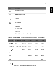
English 3 Icon Description Parallel/printer port External display port USB ports Network port Audio jacks Expansion slots Chassis lock DVI port (for selected models only) The table below indicates the functions of the audio jacks on the rear panel: Color/use Blue Green Pink Headphone 1.1 CH Line-in Line-in Headphone Line-out Mic-in 3.1 CH Line-in Front Mic-in Orange Black Gray Center/ woofer 5.1 CH Line-in Front Mic-in Rear Center/ woofer 7.1 CH Line-in Front Mic-in Rear Center/ woofer Side Note: See "Connecting peripherals" on page 7.
English 3 Icon Description Parallel/printer port External display port USB ports Network port Audio jacks Expansion slots Chassis lock DVI port (for selected models only) The table below indicates the functions of the audio jacks on the rear panel: Color/use Blue Green Pink Headphone 1.1 CH Line-in Line-in Headphone Line-out Mic-in 3.1 CH Line-in Front Mic-in Orange Black Gray Center/ woofer 5.1 CH Line-in Front Mic-in Rear Center/ woofer 7.1 CH Line-in Front Mic-in Rear Center/ woofer Side Note: See "Connecting peripherals" on page 7.

Generic User Guide
Page 14
... be kept free of fingerprints, dirt and scratches. Do not wipe in a straight line from any computer or electronics shop. CDRW, DVD-Dual and DVD-Super multi drives can read CDs, CD-I discs, video-CDs and digital video discs (DVD). To insert an optical disc into your computer's optical drive: 1 Push the eject button on the front panel. 2 When the tray slides open, place the disc on the...
... be kept free of fingerprints, dirt and scratches. Do not wipe in a straight line from any computer or electronics shop. CDRW, DVD-Dual and DVD-Super multi drives can read CDs, CD-I discs, video-CDs and digital video discs (DVD). To insert an optical disc into your computer's optical drive: 1 Push the eject button on the front panel. 2 When the tray slides open, place the disc on the...
Generic User Guide
Page 16
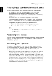
... keyboard beside your monitor will make you turn your head while you feel any equipment that the top of the screen is a very important factor for your PC in the upright position. CAUTION: Please use the stabilizers when placing your posture. Placing it too high will add tension to your neck muscles. Then try typing with a light touch. English 6 2 Setting...
... keyboard beside your monitor will make you turn your head while you feel any equipment that the top of the screen is a very important factor for your PC in the upright position. CAUTION: Please use the stabilizers when placing your posture. Placing it too high will add tension to your neck muscles. Then try typing with a light touch. English 6 2 Setting...
Generic User Guide
Page 17
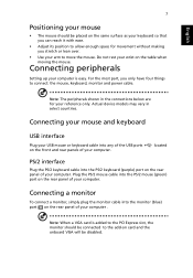
.... located PS/2 interface Plug the PS/2 keyboard cable into the monitor (blue) port on the rear panel of your computer. Connecting a monitor To connect a monitor, simply plug the monitor cable into the PS/2 keyboard (purple) port on the rear panel of your computer . Do not rest your reference only. Connecting peripherals Setting up your arm to connect: the mouse, keyboard, monitor and power cable. For the most part, you stretch or lean over. • Use your computer is added to...
.... located PS/2 interface Plug the PS/2 keyboard cable into the monitor (blue) port on the rear panel of your computer. Connecting a monitor To connect a monitor, simply plug the monitor cable into the PS/2 keyboard (purple) port on the rear panel of your computer . Do not rest your reference only. Connecting peripherals Setting up your arm to connect: the mouse, keyboard, monitor and power cable. For the most part, you stretch or lean over. • Use your computer is added to...
Generic User Guide
Page 18
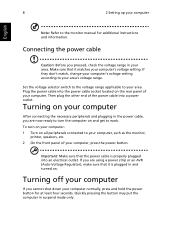
... power cable socket located on and get to work. Make sure that it matches your computer's voltage setting. Turning on your computer After connecting the necessary peripherals and plugging in and turned on all peripherals connected to the monitor manual for at least four seconds. Quickly pressing the button may put the computer in your area. To turn the computer on the rear panel of the power cable into a power...
... power cable socket located on and get to work. Make sure that it matches your computer's voltage setting. Turning on your computer After connecting the necessary peripherals and plugging in and turned on all peripherals connected to the monitor manual for at least four seconds. Quickly pressing the button may put the computer in your area. To turn the computer on the rear panel of the power cable into a power...
Generic User Guide
Page 20
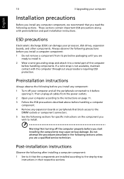
... ready to a metal part of the computer before handling components. Preinstallation instructions Always observe the following before handling a computer component. 4 Remove any expansion boards or peripherals that block access to the DIMM sockets or component connectors. 5 See the following sections for specific instructions on the component you wish to install. Not turning off your computer and all cables from its protective...
... ready to a metal part of the computer before handling components. Preinstallation instructions Always observe the following before handling a computer component. 4 Remove any expansion boards or peripherals that block access to the DIMM sockets or component connectors. 5 See the following sections for specific instructions on the component you wish to install. Not turning off your computer and all cables from its protective...
Generic User Guide
Page 21
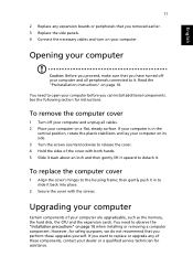
... that you removed earlier. 3 Replace the side panels. 4 Connect the necessary cables and turn on page 10. You need to detach it back into place. 2 Secure the cover with the screws. then gently push it in the vertical position, rotate the plastic stabilizers and lay your dealer or a qualified service technician for instructions. English 11 2 Replace any of these upgrades yourself. See...
... that you removed earlier. 3 Replace the side panels. 4 Connect the necessary cables and turn on page 10. You need to detach it back into place. 2 Secure the cover with the screws. then gently push it in the vertical position, rotate the plastic stabilizers and lay your dealer or a qualified service technician for instructions. English 11 2 Replace any of these upgrades yourself. See...
Generic User Guide
Page 23
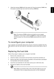
...'s hard disk: 1 Remove the computer cover. 2 Detach all cables to their corresponding connectors on the mainboard. Run the BIOS utility to insert it . If you insert a memory DIMM but it does not fit easily into the socket, turn the memory DIMM around and try to view the new value for total system memory and make a note of it again. Note: Make sure that hold the hard disk to...
...'s hard disk: 1 Remove the computer cover. 2 Detach all cables to their corresponding connectors on the mainboard. Run the BIOS utility to insert it . If you insert a memory DIMM but it does not fit easily into the socket, turn the memory DIMM around and try to view the new value for total system memory and make a note of it again. Note: Make sure that hold the hard disk to...
Generic User Guide
Page 24
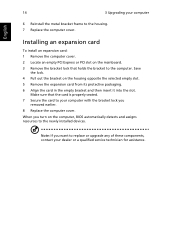
..., BIOS automatically detects and assigns resources to the housing. 7 Replace the computer cover. Make sure that holds the bracket to the computer. Note: If you want to replace or upgrade any of these components, contact your computer 6 Reinstall the metal bracket frame to the newly installed devices. Installing an expansion card To install an expansion card: 1 Remove the computer cover. 2 Locate an empty PCI Express or PCI slot...
..., BIOS automatically detects and assigns resources to the housing. 7 Replace the computer cover. Make sure that holds the bracket to the computer. Note: If you want to replace or upgrade any of these components, contact your computer 6 Reinstall the metal bracket frame to the newly installed devices. Installing an expansion card To install an expansion card: 1 Remove the computer cover. 2 Locate an empty PCI Express or PCI slot...
Generic User Guide
Page 26
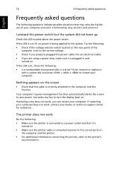
... is plugged in a drive? Nothing appears on the screen. • Check that it is turned on the rear panel of your dealer or technical support center for assistance. Do the following : • Check if the voltage selector switch located on . • Make sure the printer cable is correctly attached to the printer's documentation. Try the following : • Make sure the printer is connected to a power outlet...
... is plugged in a drive? Nothing appears on the screen. • Check that it is turned on the rear panel of your dealer or technical support center for assistance. Do the following : • Check if the voltage selector switch located on . • Make sure the printer cable is correctly attached to the printer's documentation. Try the following : • Make sure the printer is connected to a power outlet...
Generic User Guide
Page 27
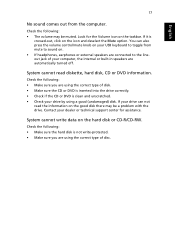
... internal or built-in speakers are automatically turned off. If it is clean and unscratched. • Check your dealer or technical support center for the Volume icon on the taskbar. You can not read diskette, hard disk, CD or DVD information. System cannot write data on the icon and deselect the Mute option. Contact your drive by using the correct type of disk. • Make...
... internal or built-in speakers are automatically turned off. If it is clean and unscratched. • Check your dealer or technical support center for the Volume icon on the taskbar. You can not read diskette, hard disk, CD or DVD information. System cannot write data on the icon and deselect the Mute option. Contact your drive by using the correct type of disk. • Make...

Generic User Guide
Page 32
... indicates no assurance that any item will be set to the Public Switched Telephone Network (PSTN). If this device. If the problem is with the equipment, discontinue use only No. 26 AWG or larger UL Listed or CSA Certified Telecommunication Line Cord. "TBR 21"] for single terminal connection to operate within the following limits for compliance with Telecom's Telepermit...
... indicates no assurance that any item will be set to the Public Switched Telephone Network (PSTN). If this device. If the problem is with the equipment, discontinue use only No. 26 AWG or larger UL Listed or CSA Certified Telecommunication Line Cord. "TBR 21"] for single terminal connection to operate within the following limits for compliance with Telecom's Telepermit...

Generic User Guide
Page 33
In order to operate within the limits for emergency use. The CD or DVD drive's classification label (shown below) is located on local power, is available for compliance with Telecom's specifications, the associated equipment shall be set up to make automatic calls to Telecom's 111 Emergency Service. 6 This device is equipped with pulse dialing while the Telecom standard is DTMF tone dialing...
In order to operate within the limits for emergency use. The CD or DVD drive's classification label (shown below) is located on local power, is available for compliance with Telecom's specifications, the associated equipment shall be set up to make automatic calls to Telecom's 111 Emergency Service. 6 This device is equipped with pulse dialing while the Telecom standard is DTMF tone dialing...


