

Veriton 3000 Service Guide
Page 5
... the Hard Disk 54 Disassembling the Hard Disk Drive 54 Disassembling the Lock Bracket 55 Removing the LAN, Modem and Riser Boards 56 Removing the Battery 57 Removing the Intrusion Alarm 58 Removing the Power Supply 59 Removing the Front Panel 60 Removing the Audio Board 61 V
... the Hard Disk 54 Disassembling the Hard Disk Drive 54 Disassembling the Lock Bracket 55 Removing the LAN, Modem and Riser Boards 56 Removing the Battery 57 Removing the Intrusion Alarm 58 Removing the Power Supply 59 Removing the Front Panel 60 Removing the Audio Board 61 V
Veriton 3000 Service Guide
Page 13
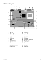
Main Board Layout 2 5 24 26 23 22 21 20 1 2 3 4 5 5 6 7 8 9 11 10 1 SiS 301 2 PCI Riser Slot 3 SiS 630 NB (w/ AGP) 4 Buzzer 5 Crystal 6 Flash ROM 7 Battery 8 Slim FDD Connector 9 SiS 950 Super I/O 10 Front Port 11 IDE1 Connector 12 Slim CD-ROM Connector 13 Power Connector 19 18 17 16 15 14 13 12 14 Clock Generator 15 Regulator 3.3V 16 DIP Switch 17 2 DIMM Slots 18 Socket 370 19 Fan Connector 20 PS/2 mouse and keyboard port 21 LPT1, VGA & Com1 22 RJ45 & 2 USB ports 23 DVI 24 Line-In jack 25 Line-Out jack 26 MIDI/Game port Chapter 1 7
Main Board Layout 2 5 24 26 23 22 21 20 1 2 3 4 5 5 6 7 8 9 11 10 1 SiS 301 2 PCI Riser Slot 3 SiS 630 NB (w/ AGP) 4 Buzzer 5 Crystal 6 Flash ROM 7 Battery 8 Slim FDD Connector 9 SiS 950 Super I/O 10 Front Port 11 IDE1 Connector 12 Slim CD-ROM Connector 13 Power Connector 19 18 17 16 15 14 13 12 14 Clock Generator 15 Regulator 3.3V 16 DIP Switch 17 2 DIMM Slots 18 Socket 370 19 Fan Connector 20 PS/2 mouse and keyboard port 21 LPT1, VGA & Com1 22 RJ45 & 2 USB ports 23 DVI 24 Line-In jack 25 Line-Out jack 26 MIDI/Game port Chapter 1 7

Veriton 3000 Service Guide
Page 26
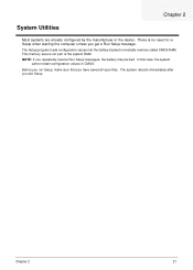
...Chapter 2 21 Chapter 2 System Utilities Most systems are already configured by the manufacturer or the dealer. The Setup program loads configuration values into the battery-backed nonvolatile memory called CMOS RAM. This memory area is no need to run Setup, make sure that you get a Run Setup message. The ...system reboots immediately after you repeatedly receive Run Setup messages, the battery may be bad. There is not part of the system RAM. Before you run Setup when starting the computer unless you have saved all ...
...Chapter 2 21 Chapter 2 System Utilities Most systems are already configured by the manufacturer or the dealer. The Setup program loads configuration values into the battery-backed nonvolatile memory called CMOS RAM. This memory area is no need to run Setup, make sure that you get a Run Setup message. The ...system reboots immediately after you repeatedly receive Run Setup messages, the battery may be bad. There is not part of the system RAM. Before you run Setup when starting the computer unless you have saved all ...

Veriton 3000 Service Guide
Page 43
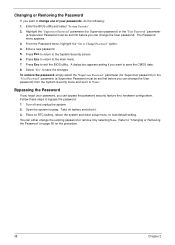
... menu and set it to "None". Press Esc to the main menu. 7. A dialog box appears asking if you want to save the changes. Turn off battery and short it by selecting None. From the Password menu, highlight the "Set or Change Password" option. 4. Press Esc to return to exit the BIOS... Password must be set first before you can change one of your passwords, do the following: 1. Refer to "Changing or Removing the Password" on RTC battery, reboot the system and enter setup menu, to save the CMOS data. 8.
... menu and set it to "None". Press Esc to the main menu. 7. A dialog box appears asking if you want to save the changes. Turn off battery and short it by selecting None. From the Password menu, highlight the "Set or Change Password" option. 4. Press Esc to return to exit the BIOS... Password must be set first before you can change one of your passwords, do the following: 1. Refer to "Changing or Removing the Password" on RTC battery, reboot the system and enter setup menu, to save the CMOS data. 8.
Veriton 3000 Service Guide
Page 53
.... There is not part of the system RAM. NOTE: If you exit Setup. The system reboots immediately after you repeatedly receive Run Setup messages, the battery may be bad. This memory area is no need to ru Setup when starting the computer unless you have saved all open files. The Setup...
.... There is not part of the system RAM. NOTE: If you exit Setup. The system reboots immediately after you repeatedly receive Run Setup messages, the battery may be bad. This memory area is no need to ru Setup when starting the computer unless you have saved all open files. The Setup...
Veriton 3000 Service Guide
Page 70
... before you can either change the existing password or remove it by selecting None. Turn off battery and short it to "None". Open the system housing. Refer to "Changing or Removing the Password" on RTC battery, reboot the system and enter setup menu, to load default setting. Press Esc to the System...
... before you can either change the existing password or remove it by selecting None. Turn off battery and short it to "None". Open the system housing. Refer to "Changing or Removing the Password" on RTC battery, reboot the system and enter setup menu, to load default setting. Press Esc to the System...
Veriton 3000 Service Guide
Page 89
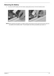
To remove the RTC battery from the holder, please gently remove it from the holder by hand. Thus the system can boot up successfully upon power on. Chapter 3 57 Removing the Battery 1. NOTE: When replacing new battery to the M/B, engineer should plug in the AC power first and then press the new battery into the battery holder.
To remove the RTC battery from the holder, please gently remove it from the holder by hand. Thus the system can boot up successfully upon power on. Chapter 3 57 Removing the Battery 1. NOTE: When replacing new battery to the M/B, engineer should plug in the AC power first and then press the new battery into the battery holder.
Veriton 3000 Service Guide
Page 98
...) T Interrupt system (8259 module) T Three programmable timers (system timer and 8254 module) T ROM subsystem T RAM subsystem T RTC RAM subsystem and real time clock/calendar with battery backup T Onboard serial interface controller T Onboard parallel interface controller T Embedded hard disk interface and one diskette drive interface T Keyboard and auxiliary device controllers T I/O ports T PS...
...) T Interrupt system (8259 module) T Three programmable timers (system timer and 8254 module) T ROM subsystem T RAM subsystem T RTC RAM subsystem and real time clock/calendar with battery backup T Onboard serial interface controller T Onboard parallel interface controller T Embedded hard disk interface and one diskette drive interface T Keyboard and auxiliary device controllers T I/O ports T PS...
Veriton 3000 Service Guide
Page 100
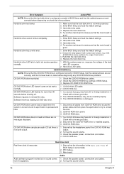
... default settings in BIOS Setup is not set in Setup. 2. PS/2 mouse. 5. Main board. Ensure that are NOT factoryinstalled and then reboot the system. 1. RTC battery. 4. IDE hard disk drive cable/connection. 5. then reboot the system. 3. Remove all adapter cards that are NOT factory- PS/2 keyboard. 4. BIOS Message CPU Clock Mismatch...
... default settings in BIOS Setup is not set in Setup. 2. PS/2 mouse. 5. Main board. Ensure that are NOT factoryinstalled and then reboot the system. 1. RTC battery. 4. IDE hard disk drive cable/connection. 5. then reboot the system. 3. Remove all adapter cards that are NOT factory- PS/2 keyboard. 4. BIOS Message CPU Clock Mismatch...
Veriton 3000 Service Guide
Page 101
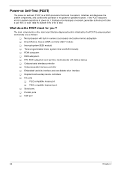
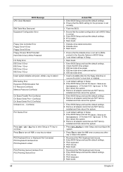
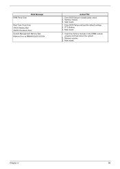
RAM Parity Error BIOS Message Real Time Clock Error CMOS Battery Bad CMOS Checksum Error System Management Memory Bad Memory Error at MMMM:SSSS:OOOOh Action/FRU 1. Main board. 1. Memory module. 3. Main board. 1. Enter BIOS Setup and load the default settings. 2. Insert the memory modules in the DIMM sockets properly and then reboot the system. 2. Chapter 4 69 Memory module. 3. RTC Battery. 3. Enter BIOS Setup to disable parity check. 2. Main board.
RAM Parity Error BIOS Message Real Time Clock Error CMOS Battery Bad CMOS Checksum Error System Management Memory Bad Memory Error at MMMM:SSSS:OOOOh Action/FRU 1. Main board. 1. Memory module. 3. Main board. 1. Enter BIOS Setup and load the default settings. 2. Insert the memory modules in the DIMM sockets properly and then reboot the system. 2. Chapter 4 69 Memory module. 3. RTC Battery. 3. Enter BIOS Setup to disable parity check. 2. Main board.
Veriton 3000 Service Guide
Page 104
... no messages displayed. CD/DVD-ROM drive LED doesn't come on it . CD/DVD-ROM drive can play an audio CD but works normally. 1. RTC battery. 3. Check the speaker power, connections and cables. Replace the hard disk drive. 5. CD/DVD-ROM LED cable. 2. CD/DVD-ROM drive does not read and...
... no messages displayed. CD/DVD-ROM drive LED doesn't come on it . CD/DVD-ROM drive can play an audio CD but works normally. 1. RTC battery. 3. Check the speaker power, connections and cables. Replace the hard disk drive. 5. CD/DVD-ROM LED cable. 2. CD/DVD-ROM drive does not read and...
Veriton 3000 Service Guide
Page 112
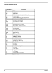
... CN11 CN12 CN13 CN14 CN15 CN16 CN18 CN19 JP1 JP2 JP3 JP5 JP11 JP12 JP13 PH1 PH2 SW1 U2 U14 U16 U18 U27 U29 Description Battery DIMM socket 1 DIMM socket 2 PS/2 mouse (upper) and keyboard (lower) ports Power Connector Serial port / Parallel port / VGA port connector Network (upper) and USB (lower...
... CN11 CN12 CN13 CN14 CN15 CN16 CN18 CN19 JP1 JP2 JP3 JP5 JP11 JP12 JP13 PH1 PH2 SW1 U2 U14 U16 U18 U27 U29 Description Battery DIMM socket 1 DIMM socket 2 PS/2 mouse (upper) and keyboard (lower) ports Power Connector Serial port / Parallel port / VGA port connector Network (upper) and USB (lower...


