Pre-Install Intel® AHCI Driver for Windows XP® Operating System
Page 1
... F6 driver files to install operating system. Connect the USB floppy drive and then boot up from the Microsoft® Windows XP® Professional/Home Edition Setup Disc to a blank 1.44MB floppy diskette. Pre-Install Intel® AHCI Driver for Windows XP® Operating System Pre-Installation Using the F6 Method Notes: Before you start to install Microsoft® Windows XP® operating system, you will need an optical drive, a USB floppy drive, a blank...
... F6 driver files to install operating system. Connect the USB floppy drive and then boot up from the Microsoft® Windows XP® Professional/Home Edition Setup Disc to a blank 1.44MB floppy diskette. Pre-Install Intel® AHCI Driver for Windows XP® Operating System Pre-Installation Using the F6 Method Notes: Before you start to install Microsoft® Windows XP® operating system, you will need an optical drive, a USB floppy drive, a blank...
Quick Start Guide
Page 5
... instructions on how to be more on such subjects as using the keyboard and audio, etc. The TravelMate Series Generic User Guide contains useful information applying to the AcerSystem User Guide. It covers basic topics such as system utilities, data recovery, expansion options and troubleshooting. This guide contains detailed information on how your computer can help you use Adobe Reader, access the Help and Support menu. Your guides To help you to use your Acer notebook...
... instructions on how to be more on such subjects as using the keyboard and audio, etc. The TravelMate Series Generic User Guide contains useful information applying to the AcerSystem User Guide. It covers basic topics such as system utilities, data recovery, expansion options and troubleshooting. This guide contains detailed information on how your computer can help you use Adobe Reader, access the Help and Support menu. Your guides To help you to use your Acer notebook...
Quick Start Guide
Page 7
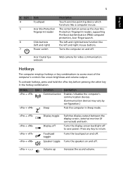
... Eye Web camera for video communication. 5 English # Icon 4 5 6 7 Item Touchpad Acer Bio-Protection fingerprint reader Click buttons (left and right buttons function like screen brightness and volume output. To activate hotkeys, press and hold the key before pressing the other key in Sleep mode. + + + + Display toggle Display off Touchpad toggle Speaker toggle Switches display output between the display screen, external monitor (if connected) and both. The center button serves as the Acer BioProtection fingerprint reader, supporting Pre-Boot Authentication (PBA...
... Eye Web camera for video communication. 5 English # Icon 4 5 6 7 Item Touchpad Acer Bio-Protection fingerprint reader Click buttons (left and right buttons function like screen brightness and volume output. To activate hotkeys, press and hold the key before pressing the other key in Sleep mode. + + + + Display toggle Display off Touchpad toggle Speaker toggle Switches display output between the display screen, external monitor (if connected) and both. The center button serves as the Acer BioProtection fingerprint reader, supporting Pre-Boot Authentication (PBA...

Service Guide
Page 6
... Keyboard 13 Hardware Specifications and Configurations 23 Chapter 2 System Utilities 32 BIOS Setup Utility 32 BIOS Flash Utility 44 Chapter 3 Machine DIsassembly and Replacement 45 General Information 46 Disassembly Procedure Flowchart 47 Removing the Battery Pack 49 Removing the HDD Module and the miniPCI 50 Disassembling the Main Unit into Upper Case and Lower Case 52 Disassembling the Lower Case 54 Disassembling the LCD Module and Upper Case 57 Disassembling the LCD Module 60 Disassembling the External Modules 62 Chapter 4 Troubleshooting...
... Keyboard 13 Hardware Specifications and Configurations 23 Chapter 2 System Utilities 32 BIOS Setup Utility 32 BIOS Flash Utility 44 Chapter 3 Machine DIsassembly and Replacement 45 General Information 46 Disassembly Procedure Flowchart 47 Removing the Battery Pack 49 Removing the HDD Module and the miniPCI 50 Disassembling the Main Unit into Upper Case and Lower Case 52 Disassembling the Lower Case 54 Disassembling the LCD Module and Upper Case 57 Disassembling the LCD Module 60 Disassembling the External Modules 62 Chapter 4 Troubleshooting...
Service Guide
Page 7
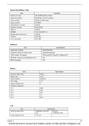
...-PCI(Manufacturing option) Keyboard and Pointing Device ! 84/85/88 keys Windows keyboard ! Built-in -Ring ready ! Multimedia ! ! ! ! Built-in dual speakers Internal Microphone x1 which combines Sound Blaster® Pro and MS-Sound compatible Azalia stereo, SPDIF supported Communication ! 56K ITU V.92 modem with dual soDimm modules ! 60/80 GB and above high-capacity, Enhanced-IDE hard disk Display ! ! ! ! ! Integrated Bluetooth® ! Chapter 1 1 download service manual and resetter printer...
...-PCI(Manufacturing option) Keyboard and Pointing Device ! 84/85/88 keys Windows keyboard ! Built-in -Ring ready ! Multimedia ! ! ! ! Built-in dual speakers Internal Microphone x1 which combines Sound Blaster® Pro and MS-Sound compatible Azalia stereo, SPDIF supported Communication ! 56K ITU V.92 modem with dual soDimm modules ! 60/80 GB and above high-capacity, Enhanced-IDE hard disk Display ! ! ! ! ! Integrated Bluetooth® ! Chapter 1 1 download service manual and resetter printer...
Service Guide
Page 8
Smart Card support Kensington lock slot BIOS user and supervisor password support Software Acer Launch Manager Acer eManager Acer System Recovery CD Acer disc-to-disc recovery3 Norton AntiVirusTM Adobe® Reader® CyberLinlk® PowerDVD® MTI CD-MakerTM GridVista 2 Chapter 1 download service manual and resetter printer at http://printer1.blogspot.com Expansion ! ! ! One Type II CardBus PC Card slot Upgradeable memory modules Acer EasyPort I/O Ports One Type II PC Card slot Modem (RJ-11) port One RJ-45 jack for LAN (Ethernet 10/100...
Smart Card support Kensington lock slot BIOS user and supervisor password support Software Acer Launch Manager Acer eManager Acer System Recovery CD Acer disc-to-disc recovery3 Norton AntiVirusTM Adobe® Reader® CyberLinlk® PowerDVD® MTI CD-MakerTM GridVista 2 Chapter 1 download service manual and resetter printer at http://printer1.blogspot.com Expansion ! ! ! One Type II CardBus PC Card slot Upgradeable memory modules Acer EasyPort I/O Ports One Type II PC Card slot Modem (RJ-11) port One RJ-45 jack for LAN (Ethernet 10/100...
Service Guide
Page 18
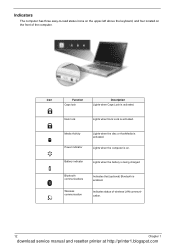
Media Activity Power indicator Lights when the disc or AcerMedia is on the front of wireless LAN communication. 12 Chapter 1 download service manual and resetter printer at http://printer1.blogspot.com Lights when the computer is activated. Num lock Lights when Num Lock is enabled. Indicators The computer has three easy-to-read status icons on the upper-left above the keyboard, and four located on . Battery indicator Lights when the battery is being charged Bluetooth communications...
Media Activity Power indicator Lights when the disc or AcerMedia is on the front of wireless LAN communication. 12 Chapter 1 download service manual and resetter printer at http://printer1.blogspot.com Lights when the computer is activated. Num lock Lights when Num Lock is enabled. Indicators The computer has three easy-to-read status icons on the upper-left above the keyboard, and four located on . Battery indicator Lights when the battery is being charged Bluetooth communications...
Service Guide
Page 29
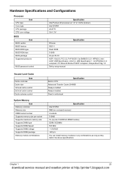
... enabled Always enabled Fixed in write-back Specification Intel 915PM 0MB (no on-board memory) 2 sockets 512MB 1G (by two 512MB SO-DIMM module) DDRII SODIMM 533 MHz +1.8VSUS 200 pin You can install memory modules in any combinations as long as they match the above specifications. Hardware Specifications and Configurations Processor Item CPU type Core logic CPU package CPU core voltage BIOS Item BIOS vendor BIOS Version BIOS ROM type BIOS ROM size BIOS package Supported protocols BIOS password control Specification...
... enabled Always enabled Fixed in write-back Specification Intel 915PM 0MB (no on-board memory) 2 sockets 512MB 1G (by two 512MB SO-DIMM module) DDRII SODIMM 533 MHz +1.8VSUS 200 pin You can install memory modules in any combinations as long as they match the above specifications. Hardware Specifications and Configurations Processor Item CPU type Core logic CPU package CPU core voltage BIOS Item BIOS vendor BIOS Version BIOS ROM type BIOS ROM size BIOS package Supported protocols BIOS password control Specification...
Service Guide
Page 35
... I/O controller Audio controller Video controller Hard disk drive controller Keyboard controller USB 2.0 MODEM Wireless 802.11a+b/a+b+g PCMCIA 5-in-1 card reader Controller Intel 915PM Express Chipset NSC87383, 3.3V LPC interface Realtek ALC880 Codec ATI M26P ICH6-M NS PC87591 ICH6-M V.92, Ambit MDC 1.5 ICH6-M OZ711M3 OZ711M3 Keyboard Item Keyboard controller Keyboard vendor & model name Total number of keypads Windows logo key and Application key Multi-Language Specification SIO NSC97551 Standard keyboard 84 keys(US),85 keys(EU), 88keys(JP) Yes Yes Battery...
... I/O controller Audio controller Video controller Hard disk drive controller Keyboard controller USB 2.0 MODEM Wireless 802.11a+b/a+b+g PCMCIA 5-in-1 card reader Controller Intel 915PM Express Chipset NSC87383, 3.3V LPC interface Realtek ALC880 Codec ATI M26P ICH6-M NS PC87591 ICH6-M V.92, Ambit MDC 1.5 ICH6-M OZ711M3 OZ711M3 Keyboard Item Keyboard controller Keyboard vendor & model name Total number of keypads Windows logo key and Application key Multi-Language Specification SIO NSC97551 Standard keyboard 84 keys(US),85 keys(EU), 88keys(JP) Yes Yes Battery...

Service Guide
Page 42
... enabled. Option: Auto or Both Allows user to factory defaults. Disabled: Customer Logo is not displayed, and Summary Screen is disabled. Both: Simultaneously enable both the integrated LCD screen and the system's external video port (for an external CRT or projector). Option: Enabled or Disabled Auto: During power process, the system will be in CRT (or projector) only mode. Allow user to control the settings in these cases. Parameter Quiet Boot Power on display Network Boot F12 Boot Menu D2D Recovery Description Format/Option...
... enabled. Option: Auto or Both Allows user to factory defaults. Disabled: Customer Logo is not displayed, and Summary Screen is disabled. Both: Simultaneously enable both the integrated LCD screen and the system's external video port (for an external CRT or projector). Option: Enabled or Disabled Auto: During power process, the system will be in CRT (or projector) only mode. Allow user to control the settings in these cases. Parameter Quiet Boot Power on display Network Boot F12 Boot Menu D2D Recovery Description Format/Option...
Service Guide
Page 45
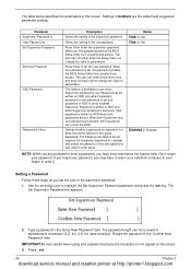
... you forget your dealer to HDD when both passwords can unlock the HDD. Use the w andy keys to set , this group happened. The user can be grayed out if the user password was used to HDD only when Supervisor password is written to reset it. Type a password in the "Confirm New Password" field. Parameter Supervisor Password is User Password is Set Supervisor Password Set User Password HDD Password Password on the screen. 3. When set the user password. Password can enter Setup menu only and does not have...
... you forget your dealer to HDD when both passwords can unlock the HDD. Use the w andy keys to set , this group happened. The user can be grayed out if the user password was used to HDD only when Supervisor password is written to reset it. Type a password in the "Confirm New Password" field. Parameter Supervisor Password is User Password is Set Supervisor Password Set User Password HDD Password Password on the screen. 3. When set the user password. Password can enter Setup menu only and does not have...
Service Guide
Page 46
... e. 3. Type a password in the Enter New Password and Confirm New Password fields. After setting the password, the computer sets the User Password parameter to save the changes and exit the BIOS Setup Utility. When you can enable the Password on boot parameter. 5. Changing a Password 1. Use the w and y keys to highlight the Set Supervisor Password parameter and press the e key. Use the w and y keys to highlight the Set Supervisor Password parameter and press the e key. If desired, you are done, press u to "Clear...
... e. 3. Type a password in the Enter New Password and Confirm New Password fields. After setting the password, the computer sets the User Password parameter to save the changes and exit the BIOS Setup Utility. When you can enable the Password on boot parameter. 5. Changing a Password 1. Use the w and y keys to highlight the Set Supervisor Password parameter and press the e key. Use the w and y keys to highlight the Set Supervisor Password parameter and press the e key. If desired, you are done, press u to "Clear...
Service Guide
Page 49
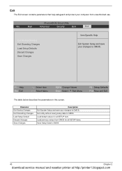
... Discarding Changes Load Setup Default Discard Changes Save Changes Description Exit System Setup and save your changes to CMOS. Exit The Exit screen contains parameters that help safeguard and protect your computer from CMOS for all SETUP items. Save Setup Data to CMOS. 43 Chapter 2 download service manual and resetter printer at http://printer1.blogspot.com Load previous values from unauthorized use. PhoenixBIOS Setup Utility Info. Exit utility without saving setup...
... Discarding Changes Load Setup Default Discard Changes Save Changes Description Exit System Setup and save your changes to CMOS. Exit The Exit screen contains parameters that help safeguard and protect your computer from CMOS for all SETUP items. Save Setup Data to CMOS. 43 Chapter 2 download service manual and resetter printer at http://printer1.blogspot.com Load previous values from unauthorized use. PhoenixBIOS Setup Utility Info. Exit utility without saving setup...

Service Guide
Page 50
....com Use the Phlash utility to finish BIOS flash, you run the Phlash. 1. If the battery pack does not contain enough power to update the system BIOS flash ROM. Chapter 2 44 download service manual and resetter printer at hand, then you should create a Crisis Recovery Diskette before you use the Phlash utility. NOTE: Do not install memory-related drivers (XMS, EMS, DPMI) when you use the Phlash. New versions of system programs ! Restore a BIOS...
....com Use the Phlash utility to finish BIOS flash, you run the Phlash. 1. If the battery pack does not contain enough power to update the system BIOS flash ROM. Chapter 2 44 download service manual and resetter printer at hand, then you should create a Crisis Recovery Diskette before you use the Phlash utility. NOTE: Do not install memory-related drivers (XMS, EMS, DPMI) when you use the Phlash. New versions of system programs ! Restore a BIOS...
Service Guide
Page 77
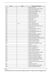
... all video adapters in system QuietBoot start (optional) Shadow video BIOS ROM Display BIOS copyright notice Display CPU type and speed Initialize EISA board Test keyboard Set key click if enabled Enable USB devices Test for unexpected interrupts Initialize POST display service Display prompt "Press F2 to enter SETUP" Disable CPU cache Test RAM between 512 and 640 KB Test extended memory Test extended memory address lines Jump to User Patch1 Configure advanced cache registers Initialize Multi Processor APIC Enable external and CPU caches Setup System Management Mode...
... all video adapters in system QuietBoot start (optional) Shadow video BIOS ROM Display BIOS copyright notice Display CPU type and speed Initialize EISA board Test keyboard Set key click if enabled Enable USB devices Test for unexpected interrupts Initialize POST display service Display prompt "Press F2 to enter SETUP" Disable CPU cache Test RAM between 512 and 640 KB Test extended memory Test extended memory address lines Jump to User Patch1 Configure advanced cache registers Initialize Multi Processor APIC Enable external and CPU caches Setup System Management Mode...
Service Guide
Page 78
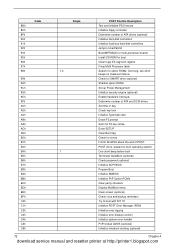
... ATA drives (optional) Initialize hard-disk controllers Initialize local-bus hard-disk controllers Jump to boot with INT 19 Initialize POST Error Manager (PEM) Initialize error logging Initialize error display function Initialize system error handler PnPnd dual CMOS (optional) Initialize notebook docking (optional) 72 Chapter 4 download service manual and resetter printer at http://printer1.blogspot.com Check for SMART drive (optional) Shadow option ROMs Set up Power Management Initialize security engine (optional) Enable hardware interrupts Determine number of ATA and SCSI drives Set time...
... ATA drives (optional) Initialize hard-disk controllers Initialize local-bus hard-disk controllers Jump to boot with INT 19 Initialize POST Error Manager (PEM) Initialize error logging Initialize error display function Initialize system error handler PnPnd dual CMOS (optional) Initialize notebook docking (optional) 72 Chapter 4 download service manual and resetter printer at http://printer1.blogspot.com Check for SMART drive (optional) Shadow option ROMs Set up Power Management Initialize security engine (optional) Enable hardware interrupts Determine number of ATA and SCSI drives Set time...
Service Guide
Page 79
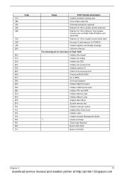
... I/O Check force recovery boot Checksum BIOS ROM Go to BIOS Set Huge Segment Initialize Multi Processor Initialize OEM special code Initialize PIC and DMA Initialize Memory type Initialize Memory size Shadow Boot Block System memory test Initialize interrupt vectors Initialize Run Time Clock Initialize video Initialize System Management Mode 1 Output one beep Clear Huge Segment Boot to Mini DOS Boot to Memory Technologies Devices such as ROM, RAM, PCMCIA, and serial disk. Unknown interrupt...
... I/O Check force recovery boot Checksum BIOS ROM Go to BIOS Set Huge Segment Initialize Multi Processor Initialize OEM special code Initialize PIC and DMA Initialize Memory type Initialize Memory size Shadow Boot Block System memory test Initialize interrupt vectors Initialize Run Time Clock Initialize video Initialize System Management Mode 1 Output one beep Clear Huge Segment Boot to Mini DOS Boot to Memory Technologies Devices such as ROM, RAM, PCMCIA, and serial disk. Unknown interrupt...
Service Guide
Page 80
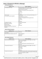
...ROM active indicators cannot work LCD is too dark LCD brightness cannot be adjusted Unreadable LCD screen Missing pels in characters Abnormal screen Wrong color displayed LCD has extra horizontal or vertical lines displayed. LCD cable LCD inverter LCD Main board Enter BIOS Utility to -FRU Error Message LCD-Related Symptoms Symptom / Error LCD backlight doesn't work HDD/CD-ROM drive Device driver Main board Action in Sequence First, plug a monitor to running "Load Default Settings" then reboot the system. LCD cable LCD inverter LCD Main board Reconnect the LCD cable LCD cable LCD...
...ROM active indicators cannot work LCD is too dark LCD brightness cannot be adjusted Unreadable LCD screen Missing pels in characters Abnormal screen Wrong color displayed LCD has extra horizontal or vertical lines displayed. LCD cable LCD inverter LCD Main board Enter BIOS Utility to -FRU Error Message LCD-Related Symptoms Symptom / Error LCD backlight doesn't work HDD/CD-ROM drive Device driver Main board Action in Sequence First, plug a monitor to running "Load Default Settings" then reboot the system. LCD cable LCD inverter LCD Main board Reconnect the LCD cable LCD cable LCD...
Service Guide
Page 81
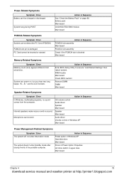
... LCD is blank. RAM module Main board Check BIOS revision Reinsert DIMM DIMM Main board Speaker-Related Symptoms Symptom / Error In Windows, multimedia programs, no sound. Action in Sequence Power option in Windows XP Hard disk drive Main board Driver of the portable computer. Power-Related Symptoms Symptom / Error Battery can power on page 66. Battery pack Main board ODD/HDD/FDD/RAM module Main board PCMCIA-Related Symptoms Symptom / Error System cannot detect the PC Card (PCMCIA) PCMCIA slot...
... LCD is blank. RAM module Main board Check BIOS revision Reinsert DIMM DIMM Main board Speaker-Related Symptoms Symptom / Error In Windows, multimedia programs, no sound. Action in Sequence Power option in Windows XP Hard disk drive Main board Driver of the portable computer. Power-Related Symptoms Symptom / Error Battery can power on page 66. Battery pack Main board ODD/HDD/FDD/RAM module Main board PCMCIA-Related Symptoms Symptom / Error System cannot detect the PC Card (PCMCIA) PCMCIA slot...

Service Guide
Page 82
...use battery until power off, then charge battery). Battery pack Main board System hangs intermittently. Reconnect hard disk/CD-ROM drives/FDD or other peripherals. Device driver Device cable Device Main board Keyboard/Touchpad-Related Symptoms Symptom / Error Keyboard (one or more keys) does not work . Touchpad does not work . Main board Press Fn+F5, LCD/CRT/Both display switching Keyboard Main board Main board Enter BIOS Setup Utility to execute "Load Default Settings" then reboot the system. Run printer self-test. Touchpad board Main board 76 Chapter 4 download service...
...use battery until power off, then charge battery). Battery pack Main board System hangs intermittently. Reconnect hard disk/CD-ROM drives/FDD or other peripherals. Device driver Device cable Device Main board Keyboard/Touchpad-Related Symptoms Symptom / Error Keyboard (one or more keys) does not work . Touchpad does not work . Main board Press Fn+F5, LCD/CRT/Both display switching Keyboard Main board Main board Enter BIOS Setup Utility to execute "Load Default Settings" then reboot the system. Run printer self-test. Touchpad board Main board 76 Chapter 4 download service...


