
TravelMate 6000/8000 Service Guide
Page 7
... Exit 42 BIOS Flash Utility 43 Chapter 3 Machine Disassembly and Replacement 45 General Information 46 Before You Begin 46 Disassembly Procedure Flowchart 47 Removing the Battery Pack 50 Removing the Optical Module/HDD Module/Wireless Lan Card and LCD module . .51 Removing the Optical Module 51 Removing the HDD Module 51...
... Exit 42 BIOS Flash Utility 43 Chapter 3 Machine Disassembly and Replacement 45 General Information 46 Before You Begin 46 Disassembly Procedure Flowchart 47 Removing the Battery Pack 50 Removing the Optical Module/HDD Module/Wireless Lan Card and LCD module . .51 Removing the Optical Module 51 Removing the HDD Module 51...

TravelMate 6000/8000 Service Guide
Page 9
...expandable up to 2GB with 2 slots T Internal removable optical drive (AcerMedia bay) T High-capacity, Enhanced-IDE hard disk T Li-Ion main battery pack T Power management system with ACPI (Advanced Configuration Power Interface) T Smart Card interface with pre-boot authentication system for added security Display T ...1400X1050 Super eXtended Graphics Array+ (SXGA+) resolution for 15.0" (specification varies depending on the model) 3D graphics engine TravelMate 8000 series employs ATI Mobility RADEONTM 9700 chipset with VGA RAM of 64MB/ 128MB (manufacturing option) delivering ground breaking 3D ...
...expandable up to 2GB with 2 slots T Internal removable optical drive (AcerMedia bay) T High-capacity, Enhanced-IDE hard disk T Li-Ion main battery pack T Power management system with ACPI (Advanced Configuration Power Interface) T Smart Card interface with pre-boot authentication system for added security Display T ...1400X1050 Super eXtended Graphics Array+ (SXGA+) resolution for 15.0" (specification varies depending on the model) 3D graphics engine TravelMate 8000 series employs ATI Mobility RADEONTM 9700 chipset with VGA RAM of 64MB/ 128MB (manufacturing option) delivering ground breaking 3D ...

TravelMate 6000/8000 Service Guide
Page 12
... Power jack CPU socket Fan connector USB connector 1394 connector PCMCIA 13 HDD connector 14 Keyboard connector 15 Touchpad board connector 16 IR 17 Main battery connector 18 Second battery connector 19 Swap bay connector 20 DDR Dimm 0 21 LCD cable connector 22 LED board connector 23 Internal microphone connector Chapter 1
... Power jack CPU socket Fan connector USB connector 1394 connector PCMCIA 13 HDD connector 14 Keyboard connector 15 Touchpad board connector 16 IR 17 Main battery connector 18 Second battery connector 19 Swap bay connector 20 DDR Dimm 0 21 LCD cable connector 22 LED board connector 23 Internal microphone connector Chapter 1
TravelMate 6000/8000 Service Guide
Page 19
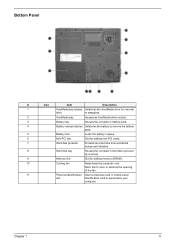
...obstruct the opening of the fan. 11 Personal identification Insert a business card or similar-sized slot identification card to remove the battery pack. 5 Battery lock Locks the battery in place. 6 Mini-PCI slot Slot for adding mini-PCI cards. 7 Hard disk protector Protects the hard disk from ... Description 1 AcerMedia bay release Unlatches the AcerMedia drive for removal latch or swapping. 2 AcerMedia bay Houses an AcerMedia drive module. 3 Battery bay Houses the computer's battery pack. 4 Battery release latches Unlatches the battery to personalize your computer.
...obstruct the opening of the fan. 11 Personal identification Insert a business card or similar-sized slot identification card to remove the battery pack. 5 Battery lock Locks the battery in place. 6 Mini-PCI slot Slot for adding mini-PCI cards. 7 Hard disk protector Protects the hard disk from ... Description 1 AcerMedia bay release Unlatches the AcerMedia drive for removal latch or swapping. 2 AcerMedia bay Houses an AcerMedia drive module. 3 Battery bay Houses the computer's battery pack. 4 Battery release latches Unlatches the battery to personalize your computer.

TravelMate 6000/8000 Service Guide
Page 20
Num lock Lights when Num Lock is charging. 12 Chapter 1 Lights orange when the battery is activated. Indicators The computer has seven easy-to-read status icons below the display screen. Media Activity Power Battery Lights when the disc or AcerMedia is in standby mode. The status LCD displays icons that show the status of the computer and its components. Lights green when the power is on and orange when the computer is activated. Icon Function Caps lock Description Lights when Caps Lock is activated.
Num lock Lights when Num Lock is charging. 12 Chapter 1 Lights orange when the battery is activated. Indicators The computer has seven easy-to-read status icons below the display screen. Media Activity Power Battery Lights when the disc or AcerMedia is in standby mode. The status LCD displays icons that show the status of the computer and its components. Lights green when the power is on and orange when the computer is activated. Icon Function Caps lock Description Lights when Caps Lock is activated.

TravelMate 6000/8000 Service Guide
Page 36
... PCMCIA Smart card reader Audio Four-in-one card reader Keyboard Item Keyboard controller Keyboard vendor & model name Total number of battery cell Package configuration Normal voltage Charge voltage Specification Sanyo Panasonic Li-ion 4400 Ah 8 4 cells in series, 2 series in ...simultaneously by software specification. Battery Item Vendor & model name Battery Type Pack capacity Number of keypads Windows logo key Internal & external keyboard work simultaneously Controller ATI Mobility RADEON 9700 for TravelMate 8000 series Intel 855GME built-in for TravelMate 6000 series BroadCom BCM5705 TI...
... PCMCIA Smart card reader Audio Four-in-one card reader Keyboard Item Keyboard controller Keyboard vendor & model name Total number of battery cell Package configuration Normal voltage Charge voltage Specification Sanyo Panasonic Li-ion 4400 Ah 8 4 cells in series, 2 series in ...simultaneously by software specification. Battery Item Vendor & model name Battery Type Pack capacity Number of keypads Windows logo key Internal & external keyboard work simultaneously Controller ATI Mobility RADEON 9700 for TravelMate 8000 series Intel 855GME built-in for TravelMate 6000 series BroadCom BCM5705 TI...
TravelMate 6000/8000 Service Guide
Page 51
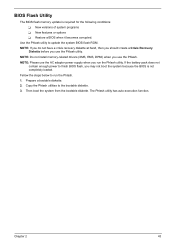
... the BIOS is required for the following conditions: T New versions of system programs T New features or options T Restore a BIOS when it becomes corrupted. If the battery pack does not contain enough power to run the Phlash utility. Chapter 2 43 NOTE: Do not install memory-related drivers (XMS, EMS, DPMI) when you...
... the BIOS is required for the following conditions: T New versions of system programs T New features or options T Restore a BIOS when it becomes corrupted. If the battery pack does not contain enough power to run the Phlash utility. Chapter 2 43 NOTE: Do not install memory-related drivers (XMS, EMS, DPMI) when you...
TravelMate 6000/8000 Service Guide
Page 54
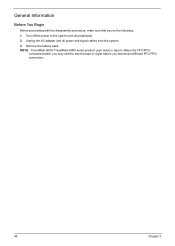
Remove the battery pack. NOTE: TravelMate 6000/ TravelMate 8000 series product uses mylar or tape to fasten the FFC/FPC/ connectors/cable, you may need to the system and all power and signal cables from the system. 3. General Information Before You Begin Before proceeding with the disassembly procedure, make sure that you disconnect different FFC/FPC/ connectors., 46 Chapter 3 Unplug the AC adapter and all peripherals. 2. Turn off the power to tear the tape or mylar before you do the following: 1.
Remove the battery pack. NOTE: TravelMate 6000/ TravelMate 8000 series product uses mylar or tape to fasten the FFC/FPC/ connectors/cable, you may need to the system and all power and signal cables from the system. 3. General Information Before You Begin Before proceeding with the disassembly procedure, make sure that you disconnect different FFC/FPC/ connectors., 46 Chapter 3 Unplug the AC adapter and all peripherals. 2. Turn off the power to tear the tape or mylar before you do the following: 1.
TravelMate 6000/8000 Service Guide
Page 55
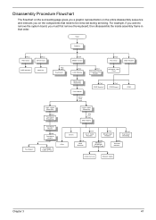
Disassembly Procedure Flowchart The flowchart on the succeeding page gives you a graphic representation on the components that order. Start Battery Hx2 HDD Door Hx2 Dimm Door HDD Module Memory Hx2 Mx3 Keyboard Ox4 Middle Cover Sx4 LCD Module Hx3 Function Key Board Hx2 PCI Door ...
Disassembly Procedure Flowchart The flowchart on the succeeding page gives you a graphic representation on the components that order. Start Battery Hx2 HDD Door Hx2 Dimm Door HDD Module Memory Hx2 Mx3 Keyboard Ox4 Middle Cover Sx4 LCD Module Hx3 Function Key Board Hx2 PCI Door ...

TravelMate 6000/8000 Service Guide
Page 58
Slide the battery latch then remove the battery. 50 Chapter 3 Removing the Battery Pack 1. Release the battery lock. 2.
Slide the battery latch then remove the battery. 50 Chapter 3 Removing the Battery Pack 1. Release the battery lock. 2.

TravelMate 6000/8000 Service Guide
Page 71
then check that power is supplied by the battery pack. Disconnect the power adapter and install the charged battery pack; Connect the power adapter and check that power is supplied. 3. Remove the battery pack. 2. If you suspect a power problem, see the appropriate power supply check in the following list: T "Check the Battery Pack" on the computer using each of the problem, power on page 64 Chapter 4 63 Power System Check To verify the symptom of the following power sources: 1.
then check that power is supplied by the battery pack. Disconnect the power adapter and install the charged battery pack; Connect the power adapter and check that power is supplied. 3. Remove the battery pack. 2. If you suspect a power problem, see the appropriate power supply check in the following list: T "Check the Battery Pack" on the computer using each of the problem, power on page 64 Chapter 4 63 Power System Check To verify the symptom of the following power sources: 1.

TravelMate 6000/8000 Service Guide
Page 72
...Tracking Pad PS2 Mode Driver. In Power Meter, confirm that has less than 7.5 Vdc after recharging, replace the battery. If the battery status indicator does not light up , replace the battery pack. If the the PS/2 mouse does not work , then replace FPC on touch pad PCB connects properly...it return to correct the problem. This symptom is working. 3. After you identify first the problem is connected O.K. 4. Check the Battery Pack To check the battery pack, do the following : From Software: 1. If the charge indicator still does not light up, replace the DC/DC charger ...
...Tracking Pad PS2 Mode Driver. In Power Meter, confirm that has less than 7.5 Vdc after recharging, replace the battery. If the battery status indicator does not light up , replace the battery pack. If the the PS/2 mouse does not work , then replace FPC on touch pad PCB connects properly...it return to correct the problem. This symptom is working. 3. After you identify first the problem is connected O.K. 4. Check the Battery Pack To check the battery pack, do the following : From Software: 1. If the charge indicator still does not light up, replace the DC/DC charger ...
TravelMate 6000/8000 Service Guide
Page 74
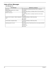
...Invalid System Configuration Data Operating system not found FRU/Action in Sequence See "Keyboard or Auxiliary Input Device Check" on page 62 RTC battery Run BIOS Setup Utility to reconfigure system time, then reboot system. Default configuration used Real time clock error Previous boot incomplete - ...66 Chapter 4 Main board Enter Setup and see if fixed disk and drive A are properly identified. RTC battery Run BIOS Setup Utility to reconfigure system, then reboot system. RTC battery Main baord "Load Default Settings" in BIOS Setup Utility. Main board "Load Default Settings" in BIOS Setup...
...Invalid System Configuration Data Operating system not found FRU/Action in Sequence See "Keyboard or Auxiliary Input Device Check" on page 62 RTC battery Run BIOS Setup Utility to reconfigure system time, then reboot system. Default configuration used Real time clock error Previous boot incomplete - ...66 Chapter 4 Main board Enter Setup and see if fixed disk and drive A are properly identified. RTC battery Run BIOS Setup Utility to reconfigure system, then reboot system. RTC battery Main baord "Load Default Settings" in BIOS Setup Utility. Main board "Load Default Settings" in BIOS Setup...
TravelMate 6000/8000 Service Guide
Page 75
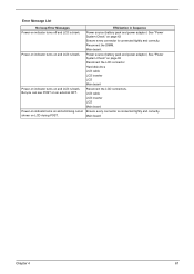
... No beep Error Messages FRU/Action in Sequence Power-on and a blinking cursor Ensure every connector is connected tightly and correctly. Power source (battery pack and power adapter.) See "Power System Check" on LCD during POST. Reconnect the LCD connectors. shown on page 63 Ensure every connector... is blank. Power source (battery pack and power adapter.) See "Power System Check" on page 63 Reconnect the LCD connector Hard disk drive LCD cable LCD inverter LCD Main...
... No beep Error Messages FRU/Action in Sequence Power-on and a blinking cursor Ensure every connector is connected tightly and correctly. Power source (battery pack and power adapter.) See "Power System Check" on LCD during POST. Reconnect the LCD connectors. shown on page 63 Ensure every connector... is blank. Power source (battery pack and power adapter.) See "Power System Check" on page 63 Reconnect the LCD connector Hard disk drive LCD cable LCD inverter LCD Main...
TravelMate 6000/8000 Service Guide
Page 80
... LCD inverter LCD Main board Enter BIOS Utility to CRT port. The system cannot power-off or on . Battery pack AC adapter See if the thermal module is OK. Battery pack Power adapter CPU Main board In Windows XP operating system, hold and press the power switch for more ...vertical lines displayed. Keyboard (if the brightness function key doesn't work ). Keyboard (if the brightness function key doesn't work ). Main board Power source (battery pack and power adapter). See "Power System Check" on page 63. Reconnect the LCD connectors. See "Power System Check" on page 63. If ...
... LCD inverter LCD Main board Enter BIOS Utility to CRT port. The system cannot power-off or on . Battery pack AC adapter See if the thermal module is OK. Battery pack Power adapter CPU Main board In Windows XP operating system, hold and press the power switch for more ...vertical lines displayed. Keyboard (if the brightness function key doesn't work ). Keyboard (if the brightness function key doesn't work ). Main board Power source (battery pack and power adapter). See "Power System Check" on page 63. Reconnect the LCD connectors. See "Power System Check" on page 63. If ...
TravelMate 6000/8000 Service Guide
Page 81
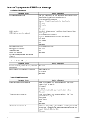
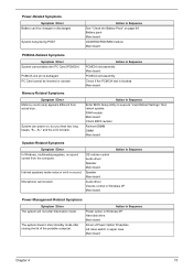
...assembly Check if the PCMCIA slot is blocked Main board Memory-Related Symptoms Symptom / Error Memory count (size) appears different from the computer. Battery pack Main board ODD/HDD/FDD/RAM module Main board PCMCIA-Related Symptoms Symptom / Error System cannot detect the PC Card (PCMCIA) PCMCIA ...slot pin is damaged. Power-Related Symptoms Symptom / Error Battery can power on page 64. Action in Sequence Power option in Windows XP Hard disk drive Main board Driver of the portable computer. RAM ...
...assembly Check if the PCMCIA slot is blocked Main board Memory-Related Symptoms Symptom / Error Memory count (size) appears different from the computer. Battery pack Main board ODD/HDD/FDD/RAM module Main board PCMCIA-Related Symptoms Symptom / Error System cannot detect the PC Card (PCMCIA) PCMCIA ...slot pin is damaged. Power-Related Symptoms Symptom / Error Battery can power on page 64. Action in Sequence Power option in Windows XP Hard disk drive Main board Driver of the portable computer. RAM ...

TravelMate 6000/8000 Service Guide
Page 82
...Setup Utility to execute "Load Setup defaults", then reboot system. Touchpad board Main board 74 Chapter 4 Battery pack Main board System hangs intermittently. Main board Battery fuel gauge in Windows doesn't go higher than 90%. Reconnect hard disk/CD-ROM drives/FDD or ...other peripherals. Check if the battery is low. Refresh battery (continue use battery until power off, then charge battery). Main board Peripheral-Related ...
...Setup Utility to execute "Load Setup defaults", then reboot system. Touchpad board Main board 74 Chapter 4 Battery pack Main board System hangs intermittently. Main board Battery fuel gauge in Windows doesn't go higher than 90%. Reconnect hard disk/CD-ROM drives/FDD or ...other peripherals. Check if the battery is low. Refresh battery (continue use battery until power off, then charge battery). Main board Peripheral-Related ...
TravelMate 6000/8000 Service Guide
Page 85
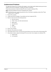
... the system is operating correctly. (See "Power System Check" on the computer. 5. If the problem remains, replace the following devices: T Non-Acer devices T Printer, mouse, and other external devices T Battery pack T Hard disk drive T DIMM T PC Cards 4. Follow these procedures to isolate the failing FRU (do not isolate non-defective FRU). If...
... the system is operating correctly. (See "Power System Check" on the computer. 5. If the problem remains, replace the following devices: T Non-Acer devices T Printer, mouse, and other external devices T Battery pack T Hard disk drive T DIMM T PC Cards 4. Follow these procedures to isolate the failing FRU (do not isolate non-defective FRU). If...

TravelMate 6000/8000 Service Guide
Page 87
... 2 CRT 3 DVI Connector 4 Docking 5 RJ45 6 RJ11 7 Power jack 8 CPU socket Chapter 5 13 HDD connector 14 Keyboard connector 15 Touchpad board connector 16 IR 17 Main battery connector 18 Second battery connector 19 Swap bay connector 20 DDR Dimm 0 79
... 2 CRT 3 DVI Connector 4 Docking 5 RJ45 6 RJ11 7 Power jack 8 CPU socket Chapter 5 13 HDD connector 14 Keyboard connector 15 Touchpad board connector 16 IR 17 Main battery connector 18 Second battery connector 19 Swap bay connector 20 DDR Dimm 0 79
TravelMate 6000/8000 Service Guide
Page 89
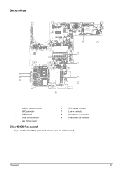
... E45 D956 D958 QD249 QD248 QS247 S731 QS5: D883 D882 D881 D87: V21 QBE: U79 H4 6 7 8 9 S734 S733 S732 211 37 QS248 36 TX3 RTC battery connector Line-in connector 4 5 6 Microphone-in connector Headphone out connector 3 S735 62 61 QBE44 B QD257 QBE53 B V58 87 86 S781 QBE43 QD256 QE31 QS24: QS251...
... E45 D956 D958 QD249 QD248 QS247 S731 QS5: D883 D882 D881 D87: V21 QBE: U79 H4 6 7 8 9 S734 S733 S732 211 37 QS248 36 TX3 RTC battery connector Line-in connector 4 5 6 Microphone-in connector Headphone out connector 3 S735 62 61 QBE44 B QD257 QBE53 B V58 87 86 S781 QBE43 QD256 QE31 QS24: QS251...


