User Manual
Page 12
... the LCD screen beside the easy-launch buttons. xii First things first We would like to thank you use Adobe Reader, access the Help and Support menu. It is not installed on your computer, clicking on your notebook. Note: Viewing the file requires Adobe Reader. If Adobe Reader is available in Portable Document Format (PDF) and comes preloaded on AcerSystem User's Guide will run the Adobe Reader setup...
... the LCD screen beside the easy-launch buttons. xii First things first We would like to thank you use Adobe Reader, access the Help and Support menu. It is not installed on your computer, clicking on your notebook. Note: Viewing the file requires Adobe Reader. If Adobe Reader is available in Portable Document Format (PDF) and comes preloaded on AcerSystem User's Guide will run the Adobe Reader setup...

User Manual
Page 36
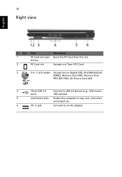
button 2 PC Card slot Accepts one Type II PC Card. 3 5-in-1 card reader Accepts Secure Digital (SD), MultiMediaCard (MMC), Memory Stick (MS), Memory Stick PRO (MS PRO), xD-Picture Card (xD). 4 Three USB 2.0 Connect to USB 2.0 devices (e.g., USB mouse, ports USB camera). 5 Ventilation slots Enable the computer to stay cool, even after prolonged use. 6 DC-in jack Connects to an AC adapter. 18 Right view English # Icon Item Description 1 PC Card slot eject Ejects the PC Card from the slot.
button 2 PC Card slot Accepts one Type II PC Card. 3 5-in-1 card reader Accepts Secure Digital (SD), MultiMediaCard (MMC), Memory Stick (MS), Memory Stick PRO (MS PRO), xD-Picture Card (xD). 4 Three USB 2.0 Connect to USB 2.0 devices (e.g., USB mouse, ports USB camera). 5 Ventilation slots Enable the computer to stay cool, even after prolonged use. 6 DC-in jack Connects to an AC adapter. 18 Right view English # Icon Item Description 1 PC Card slot eject Ejects the PC Card from the slot.
User Manual
Page 37
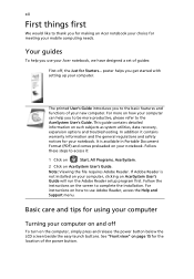
19 Rear view English # Icon Item Description 1 USB 2.0 port Connects to USB 2.0 devices (e.g., USB mouse, USB camera). 2 S-video/TV-out Connects to a television or display device (NTSC/PAL) port with S-video input. 3 External display Connects to a display device (e.g., external (VGA) port monitor, LCD projector). 4 Modem (RJ-11) port Connects to a phone line. 5 Ethernet (RJ-45) Connects to an Ethernet 10/100/1000-based port network. 6 Battery Powers the computer.
19 Rear view English # Icon Item Description 1 USB 2.0 port Connects to USB 2.0 devices (e.g., USB mouse, USB camera). 2 S-video/TV-out Connects to a television or display device (NTSC/PAL) port with S-video input. 3 External display Connects to a display device (e.g., external (VGA) port monitor, LCD projector). 4 Modem (RJ-11) port Connects to a phone line. 5 Ethernet (RJ-45) Connects to an Ethernet 10/100/1000-based port network. 6 Battery Powers the computer.
User Manual
Page 58
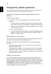
.... Remove or replace it is not lit, no power is in the external USB floppy drive? I turned on . Check the following is a list of possible situations that may be low and unable to adjust the brightness level. • The display device might be set to the computer. • If the Sleep indicator is lit, the computer is being supplied to the computer. If pressing a key does...
.... Remove or replace it is not lit, no power is in the external USB floppy drive? I turned on . Check the following is a list of possible situations that may be low and unable to adjust the brightness level. • The display device might be set to the computer. • If the Sleep indicator is lit, the computer is being supplied to the computer. If pressing a key does...
User Manual
Page 79
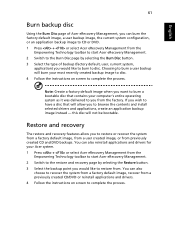
... select Acer eRecovery Management from the Empowering Technology toolbar to start Acer eRecovery Management. 2 Switch to the Burn Disc page by selecting the Restore button. 3 Select the backup point you would like to restore from. Restore and recovery The restore and recovery features allow you to restore or recover the system from a factory default image, from a user created image, or from a previously created CD/DVD or reinstall applications and drivers. 4 Follow the instructions on screen to...
... select Acer eRecovery Management from the Empowering Technology toolbar to start Acer eRecovery Management. 2 Switch to the Burn Disc page by selecting the Restore button. 3 Select the backup point you would like to restore from. Restore and recovery The restore and recovery features allow you to restore or recover the system from a factory default image, from a user created image, or from a previously created CD/DVD or reinstall applications and drivers. 4 Follow the instructions on screen to...
User Manual
Page 12
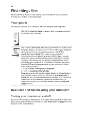
... your computer. For instructions on the computer, simply press and release the power button below the LCD screen beside the easy-launch buttons. poster helps you get started with setting up your notebook. If Adobe Reader is available in Portable Document Format (PDF) and comes preloaded on your Acer notebook, we have designed a set of guides: First off To turn on how to use your notebook. xii First things...
... your computer. For instructions on the computer, simply press and release the power button below the LCD screen beside the easy-launch buttons. poster helps you get started with setting up your notebook. If Adobe Reader is available in Portable Document Format (PDF) and comes preloaded on your Acer notebook, we have designed a set of guides: First off To turn on how to use your notebook. xii First things...
User Manual
Page 16
... Traveling internationally with the computer 46 Preparing the computer 46 What to bring with you 46 Special considerations 46 Securing your computer 47 Using a computer security lock 47 Using passwords 47 Entering passwords 48 Setting passwords 48 Expanding through options 49 Connectivity options 49 Fax/data modem 49 Built-in network feature 50 Universal Serial Bus (USB) 50 PC Card slot 51 Installing memory 52 BIOS utility 52 Boot sequence 52 Enable disk-to-disk recovery...
... Traveling internationally with the computer 46 Preparing the computer 46 What to bring with you 46 Special considerations 46 Securing your computer 47 Using a computer security lock 47 Using passwords 47 Entering passwords 48 Setting passwords 48 Expanding through options 49 Connectivity options 49 Fax/data modem 49 Built-in network feature 50 Universal Serial Bus (USB) 50 PC Card slot 51 Installing memory 52 BIOS utility 52 Boot sequence 52 Enable disk-to-disk recovery...
User Manual
Page 34
16 Right view English # Icon Item Description 1 PC Card slot eject Ejects the PC Card from the slot. button 2 PC Card slot Accepts one Type II PC Card. 3 5-in-1 card reader Accepts Secure Digital (SD), MultiMediaCard (MMC), Memory Stick (MS), Memory Stick PRO (MS PRO), xD-Picture Card (xD). 4 Three USB 2.0 Connect to USB 2.0 devices (e.g., USB mouse, ports USB camera). 5 Ventilation slots Enable the computer to stay cool, even after prolonged use. 6 DC-in jack Connects to an AC adapter.
16 Right view English # Icon Item Description 1 PC Card slot eject Ejects the PC Card from the slot. button 2 PC Card slot Accepts one Type II PC Card. 3 5-in-1 card reader Accepts Secure Digital (SD), MultiMediaCard (MMC), Memory Stick (MS), Memory Stick PRO (MS PRO), xD-Picture Card (xD). 4 Three USB 2.0 Connect to USB 2.0 devices (e.g., USB mouse, ports USB camera). 5 Ventilation slots Enable the computer to stay cool, even after prolonged use. 6 DC-in jack Connects to an AC adapter.

User Manual
Page 35
17 Rear view English # Icon Item Description 1 USB 2.0 port Connects to USB 2.0 devices (e.g., USB mouse, USB camera). 2 S-video/TV-out Connects to a television or display device (NTSC/PAL) port with S-video input. 3 External display Connects to a display device (e.g., external (VGA) port monitor, LCD projector). 4 Modem (RJ-11) port Connects to a phone line. 5 Ethernet (RJ-45) Connects to an Ethernet 10/100/1000-based port network. 6 Battery Powers the computer.
17 Rear view English # Icon Item Description 1 USB 2.0 port Connects to USB 2.0 devices (e.g., USB mouse, USB camera). 2 S-video/TV-out Connects to a television or display device (NTSC/PAL) port with S-video input. 3 External display Connects to a display device (e.g., external (VGA) port monitor, LCD projector). 4 Modem (RJ-11) port Connects to a phone line. 5 Ethernet (RJ-45) Connects to an Ethernet 10/100/1000-based port network. 6 Battery Powers the computer.
User Manual
Page 57
... key to adjust the brightness level. • The display device might be set to bring up . Nothing appears on . Press + (increase) to turn the display back on the battery, it with a system disk and press + + to resume. Press and release the power button to restart the system. Right-click on your computer. I turned on the screen. Remove or replace it may arise during the use of your Windows...
... key to adjust the brightness level. • The display device might be set to bring up . Nothing appears on . Press + (increase) to turn the display back on the battery, it with a system disk and press + + to resume. Press and release the power button to restart the system. Right-click on your computer. I turned on the screen. Remove or replace it may arise during the use of your Windows...
Service Guide
Page 8
... Machine Disassembly and Replacement 57 General Information 57 Before You Begin 57 Disassembly Procedure Flowchart 58 Disassembly Procedure 60 Removing the Battery Pack 60 Removing the HDD Module 60 Removing the Wireless LAN Card and the RAM Modules 61 Removing the Keyboard 63 Separating the LCD Module and Main Unit 64 Disassembling the Main Unit 65 LCD Disassembly 72 Chapter4 Troubleshooting 76 System Check Procedures 77 External Diskette Drive Check 77 External CD-ROM Drive Check 77 Keyboard or...
... Machine Disassembly and Replacement 57 General Information 57 Before You Begin 57 Disassembly Procedure Flowchart 58 Disassembly Procedure 60 Removing the Battery Pack 60 Removing the HDD Module 60 Removing the Wireless LAN Card and the RAM Modules 61 Removing the Keyboard 63 Separating the LCD Module and Main Unit 64 Disassembling the Main Unit 65 LCD Disassembly 72 Chapter4 Troubleshooting 76 System Check Procedures 77 External Diskette Drive Check 77 External CD-ROM Drive Check 77 Keyboard or...

Service Guide
Page 36
... user interface. Battery status For real-time battery life estimates based on current usage, refer to turn the following functions on the lower left side of your usage, there are four pre-defined profiles: Entertainment, Presentation, Word Processing, and Maximum Battery. You can adjust CPU speed, LCD brightness and other settings, or click on buttons to the panel on or off: Wireless LAN, Bluetooth, CardBus, Memory Card, Audio, and...
... user interface. Battery status For real-time battery life estimates based on current usage, refer to turn the following functions on the lower left side of your usage, there are four pre-defined profiles: Entertainment, Presentation, Word Processing, and Maximum Battery. You can adjust CPU speed, LCD brightness and other settings, or click on buttons to the panel on or off: Wireless LAN, Bluetooth, CardBus, Memory Card, Audio, and...
Service Guide
Page 50
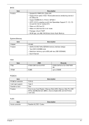
... Description Chapter 1 41 BIOS Item Feature System Memory Item Chipset Feature VGA Chip Item VRAM PCMCIA Item PCMCIA controller Card type support Number of slot Feature Audio Item Audio controller Description • Suspend to RAM (S3) / Disk (S4) • Support boot option: HDD / Removable device (media bay device) / all USB ports • Support SMBIOS 2.3, PCI2.2, WFM2.0 • ACPI 2.0/3.0 compliance with Intel Speedstep Support C1, C2, C3, C4 and S3, S4 for mobile CPU • Wake on...
... Description Chapter 1 41 BIOS Item Feature System Memory Item Chipset Feature VGA Chip Item VRAM PCMCIA Item PCMCIA controller Card type support Number of slot Feature Audio Item Audio controller Description • Suspend to RAM (S3) / Disk (S4) • Support boot option: HDD / Removable device (media bay device) / all USB ports • Support SMBIOS 2.3, PCI2.2, WFM2.0 • ACPI 2.0/3.0 compliance with Intel Speedstep Support C1, C2, C3, C4 and S3, S4 for mobile CPU • Wake on...
Service Guide
Page 52
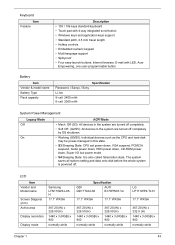
.../S5): All devices in this state. • S3 Sleeping State: CPU set power down, VGA suspend, PCMCIA suspend, Audio power down, HDD power down, CD-ROM power down, Super I/O low power mode. • S4 Sleeping State: It is also called hibernation state. Keyboard Item Feature Description • 105 / 106 keys standard keyboard • Touch pad with 4-way integrated scroll button • Windows keys and application keys support • Standard pitch, 2.5 mm travel length • Hotkey controls •...
.../S5): All devices in this state. • S3 Sleeping State: CPU set power down, VGA suspend, PCMCIA suspend, Audio power down, HDD power down, CD-ROM power down, Super I/O low power mode. • S4 Sleeping State: It is also called hibernation state. Keyboard Item Feature Description • 105 / 106 keys standard keyboard • Touch pad with 4-way integrated scroll button • Windows keys and application keys support • Standard pitch, 2.5 mm travel length • Hotkey controls •...
Service Guide
Page 65
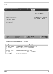
... changes to CMOS Exit utility without saving Setup data to CMOS Load default values for all SETUP items Load previous values from CMOS for all SETUP items Save Setup Data to CMOS. F1 Help Esc Exit ↑ ↓ Select Item ← → Select Menu F5/F6 Change Values Enter Select 4 Sub-Menu F9 Setup Defaults F10 Save and Exit The table below describes the parameters in this screen...
... changes to CMOS Exit utility without saving Setup data to CMOS Load default values for all SETUP items Load previous values from CMOS for all SETUP items Save Setup Data to CMOS. F1 Help Esc Exit ↑ ↓ Select Item ← → Select Menu F5/F6 Change Values Enter Select 4 Sub-Menu F9 Setup Defaults F10 Save and Exit The table below describes the parameters in this screen...
Service Guide
Page 87
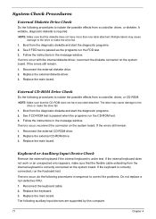
... main board. Follow the instructions in the message window. If errors occur, do the following procedures to the drive or make the drive fail. 1. Reconnect the external diskette drive. 2. If errors occur, reconnect the connector on the system board. Replace the external diskette driver. 3. Reconnect the external CD-ROM drive. 2. If the internal keyboard does not work or an unexpected error appears, make sure that the flexible cable extending from a controller, driver, or CD-ROM. Replace the keyboard. 3.
... main board. Follow the instructions in the message window. If errors occur, do the following procedures to the drive or make the drive fail. 1. Reconnect the external diskette drive. 2. If errors occur, reconnect the connector on the system board. Replace the external diskette driver. 3. Reconnect the external CD-ROM drive. 2. If the internal keyboard does not work or an unexpected error appears, make sure that the flexible cable extending from a controller, driver, or CD-ROM. Replace the keyboard. 3.

Service Guide
Page 94
... extended memory for keyboard errors Chapter 4 84 Initialize interrupt vectors POST device initialization Check ROM copyright notice Initialize I20 support Check video configuration against CMOS Initialize PCI bus and devices Initialize all video adapters in system QuietBoot start (optional) Shadow video BIOS ROM Display BIOS copyright notice Display CPU type and speed Initialize EISA board Test keyboard Set key click if enabled Enable USB devices Test for unexpected interrupts Initialize POST display service Display prompt "Press F2 to enter SETUP" Disable CPU cache Test RAM between...
... extended memory for keyboard errors Chapter 4 84 Initialize interrupt vectors POST device initialization Check ROM copyright notice Initialize I20 support Check video configuration against CMOS Initialize PCI bus and devices Initialize all video adapters in system QuietBoot start (optional) Shadow video BIOS ROM Display BIOS copyright notice Display CPU type and speed Initialize EISA board Test keyboard Set key click if enabled Enable USB devices Test for unexpected interrupts Initialize POST display service Display prompt "Press F2 to enter SETUP" Disable CPU cache Test RAM between...
Service Guide
Page 99
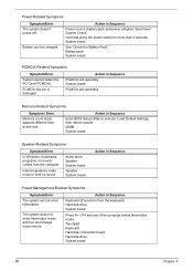
... Battery Pack". Touchpad Keyboard Hard disk connection board Hard disk drive System board 89 Chapter 4 Hold and press the power switch for more than 4 seconds. Action in Sequence Enter BIOS Setup Utility to execute "Load Default Settings, then reboot system. Action in Sequence PCMCIA slot assembly System board PCMCIA slot assembly Memory-Related Symptoms Symptom / Error Memory count (size) appears different from actual size. The system does not enter hibernation mode and four short beeps every minute. Internal speakers make...
... Battery Pack". Touchpad Keyboard Hard disk connection board Hard disk drive System board 89 Chapter 4 Hold and press the power switch for more than 4 seconds. Action in Sequence Enter BIOS Setup Utility to execute "Load Default Settings, then reboot system. Action in Sequence PCMCIA slot assembly System board PCMCIA slot assembly Memory-Related Symptoms Symptom / Error Memory count (size) appears different from actual size. The system does not enter hibernation mode and four short beeps every minute. Internal speakers make...
Service Guide
Page 100
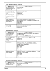
... LCD. LCD cover switch System board Action in Windows does not go higher than 90%. USB does not work correctly. Print problems Serial or parallel port device problems. Action in Sequence Reconnect the keyboard cable. System hangs intermittently. Refresh battery (continue to execute "Load Default Settings", then reboot system. Onboard Devices Configuration Run printer self-test. Action in Sequence Enter BIOS Setup Utility to use battery until power off, then charge battery). Power Management-Related Symptoms Symptom/Error The system does not enter standby mode...
... LCD. LCD cover switch System board Action in Windows does not go higher than 90%. USB does not work correctly. Print problems Serial or parallel port device problems. Action in Sequence Reconnect the keyboard cable. System hangs intermittently. Refresh battery (continue to execute "Load Default Settings", then reboot system. Onboard Devices Configuration Run printer self-test. Action in Sequence Enter BIOS Setup Utility to use battery until power off, then charge battery). Power Management-Related Symptoms Symptom/Error The system does not enter standby mode...
Service Guide
Page 108
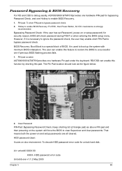
... password during POST or when entering the BIOS setup menu. However, if it is a special block of BIOS. The Pin Pad location should look as above PIN pad and then powering on or setup password) for unlock hard disk. To decode HDD password error code for security reason, BIOS will force the BIOS to a successful one hardware Pin pad under the keyboard. The user can enable this function by shorting this feature to restore the BIOS to clear Supervisor and User passwords...
... password during POST or when entering the BIOS setup menu. However, if it is a special block of BIOS. The Pin Pad location should look as above PIN pad and then powering on or setup password) for unlock hard disk. To decode HDD password error code for security reason, BIOS will force the BIOS to a successful one hardware Pin pad under the keyboard. The user can enable this function by shorting this feature to restore the BIOS to clear Supervisor and User passwords...


