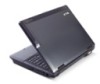
Acer TravelMate 6593 3g
View Results Below
Free Acer TravelMate 6593 manuals!
Problems with Acer TravelMate 6593?
Ask a Question
Free Acer TravelMate 6593 manuals!
Problems with Acer TravelMate 6593?
Ask a Question
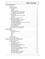
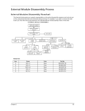
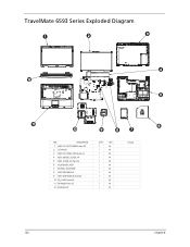
Related Manual Pages


Similar Questions

3g Radio
I think there could be a problem with the 3G button on my acer aspire 5738g laptop. I have to press ...
I think there could be a problem with the 3G button on my acer aspire 5738g laptop. I have to press ...
(Posted by brtsvdlinde 9 years ago)
