

TravelMate 620 Service Guide
Page 7
... 40 Running PQA Diagnostics Program 41 Chapter 3 Machine Disassembly and Replacement 43 General Information 44 Before You Begin 44 Disassembly Procedure Flowchart 45 Removing the Battery Pack 47 Removing the External DIMM Module 48 Removing the External Modem Combo Card 49 Removing the CD-ROM/DVD-ROM Module 50 Removing the...
... 40 Running PQA Diagnostics Program 41 Chapter 3 Machine Disassembly and Replacement 43 General Information 44 Before You Begin 44 Disassembly Procedure Flowchart 45 Removing the Battery Pack 47 Removing the External DIMM Module 48 Removing the External Modem Combo Card 49 Removing the CD-ROM/DVD-ROM Module 50 Removing the...
TravelMate 620 Service Guide
Page 9
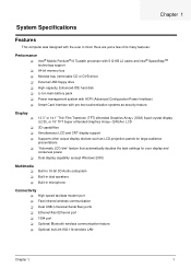
... display capability (except Windows 2000) Multimedia ! ! ! Fast infrared wireless communication ! Optional InviLink 802.11b wireless LAN Chapter 1 1 Optional Bluetooth wireless communication feature ! Li-Ion main battery pack ! High-speed fax/data modem port ! Smart Card interface with ACPI (Advanced Configuration Power Interface) ! Intel® Mobile Pentium® III Tualatin processor with...
... display capability (except Windows 2000) Multimedia ! ! ! Fast infrared wireless communication ! Optional InviLink 802.11b wireless LAN Chapter 1 1 Optional Bluetooth wireless communication feature ! Li-Ion main battery pack ! High-speed fax/data modem port ! Smart Card interface with ACPI (Advanced Configuration Power Interface) ! Intel® Mobile Pentium® III Tualatin processor with...

TravelMate 620 Service Guide
Page 16
... camera). 3 Smart Card slot Slot for Smart Card interface with pre-boot authentication systems. 4 Smart Card Eject Ejects the SmartCard from the slot. 7 Battery bay Houses the computer's battery pack. 8 Video capture kit slot Accepts the video capture kit option on the left side of the computer. 8 Chapter 1 button 5 PC Card slot...
... camera). 3 Smart Card slot Slot for Smart Card interface with pre-boot authentication systems. 4 Smart Card Eject Ejects the SmartCard from the slot. 7 Battery bay Houses the computer's battery pack. 8 Video capture kit slot Accepts the video capture kit option on the left side of the computer. 8 Chapter 1 button 5 PC Card slot...

TravelMate 620 Service Guide
Page 19
Chapter 1 11 Bottom Panel # Icon Item Description 1 AcerMedia bay Houses an AcerMedia drive module. 2 Battery bay Houses the computer's battery pack. 3 Hard disk bay Houses the computer's hard disk (secured by a screw). 4 Battery release latch Unlatches the battery to remove the battery pack. 5 Memory compartment Houses the computer's main memory. 6 Mini docking connector Connects to DockMate V mini docking station. 7 AcerMedia bay release Unlatches the AcerMedia drive for removal latch or swapping.
Chapter 1 11 Bottom Panel # Icon Item Description 1 AcerMedia bay Houses an AcerMedia drive module. 2 Battery bay Houses the computer's battery pack. 3 Hard disk bay Houses the computer's hard disk (secured by a screw). 4 Battery release latch Unlatches the battery to remove the battery pack. 5 Memory compartment Houses the computer's main memory. 6 Mini docking connector Connects to DockMate V mini docking station. 7 AcerMedia bay release Unlatches the AcerMedia drive for removal latch or swapping.
TravelMate 620 Service Guide
Page 20
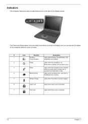
...LAN Communication capabilities are visible even when you close the display cover so you can see the status of the display screen. Blinks when a battery-low condition occurs. 3 Sleep Lights when the computer enters Standby mode and blinks when it enters into or resumes from hibernation mode. 4 ...Media Activity Lights when the floppy drive, hard disk or AcerMedia drive is active. 5 Battery Charge Lights when the battery is being charged. 6 Caps Lock Lights when Caps Lock is activated. 7 Num Lock Lights when Num Lock is on.
...LAN Communication capabilities are visible even when you close the display cover so you can see the status of the display screen. Blinks when a battery-low condition occurs. 3 Sleep Lights when the computer enters Standby mode and blinks when it enters into or resumes from hibernation mode. 4 ...Media Activity Lights when the floppy drive, hard disk or AcerMedia drive is active. 5 Battery Charge Lights when the battery is being charged. 6 Caps Lock Lights when Caps Lock is activated. 7 Num Lock Lights when Num Lock is on.

TravelMate 620 Service Guide
Page 34
Keyboard Item Windows 95 keys Yes Internal & external keyboard work simultaneously Yes Specification Battery Item Vendor & model name Battery Type Pack capacity Cell voltage Number of battery cell Package configuration Package voltage Specification Sony BTP-30A1 Li-ion 5880 mAH V/cell 9 3 cells in series, 3 series in the inverter, which stores its supported ...
Keyboard Item Windows 95 keys Yes Internal & external keyboard work simultaneously Yes Specification Battery Item Vendor & model name Battery Type Pack capacity Cell voltage Number of battery cell Package configuration Package voltage Specification Sony BTP-30A1 Li-ion 5880 mAH V/cell 9 3 cells in series, 3 series in the inverter, which stores its supported ...
TravelMate 620 Service Guide
Page 36
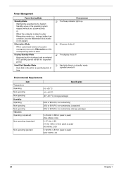
...) 25.6~250Hz: 0.5G 5~27.1Hz: 0.6G 27.1Hz~50Hz: 0.4mm (peak to peak) 50~500Hz: 2.0G 5~62.6Hz: 0.51mm (peak to enter Hibernation mode (e.g., during a battery-low condition), but the Hibernation file is about to peak) 62.6~500Hz: 4G 28 Chapter 1 Phenomenon ! The display shuts off ! Hibernation Mode When customized functions...
...) 25.6~250Hz: 0.5G 5~27.1Hz: 0.6G 27.1Hz~50Hz: 0.4mm (peak to peak) 50~500Hz: 2.0G 5~62.6Hz: 0.51mm (peak to enter Hibernation mode (e.g., during a battery-low condition), but the Hibernation file is about to peak) 62.6~500Hz: 4G 28 Chapter 1 Phenomenon ! The display shuts off ! Hibernation Mode When customized functions...

TravelMate 620 Service Guide
Page 37
... jack, 1 audio line-in jack, 1 microphone-in jack, 1 fingerprint recognition sensor Two Housing: MCS-050 Panel : Plastic Wireless Communication, Power LED, Sleep LED, Media Activity, Battery Charge, Caps Lock, Num Lock Power Memory Address Map Memory Address 00100000h-000F0000h 000F0000h-000E0000h 000E0000h-000C0000h 000C0000h-000A0000h 000A0000h-00000000h I/O Address Map 000-00F...
... jack, 1 audio line-in jack, 1 microphone-in jack, 1 fingerprint recognition sensor Two Housing: MCS-050 Panel : Plastic Wireless Communication, Power LED, Sleep LED, Media Activity, Battery Charge, Caps Lock, Num Lock Power Memory Address Map Memory Address 00100000h-000F0000h 000F0000h-000E0000h 000E0000h-000C0000h 000C0000h-000A0000h 000A0000h-00000000h I/O Address Map 000-00F...

TravelMate 620 Service Guide
Page 43
... expansion function is pressed. When it . Enabled or Disabled Ensabled or Disabled Disabled or Enabled Intel R SpeedStepTM Technology Select CPU power policy Automatic Maximum Performance Battery Optimized Reversed Boot Drive Sequence There are the default and suggested parameter settings . To set to specify the boot device sequence. Chapter 2 35 Both or...
... expansion function is pressed. When it . Enabled or Disabled Ensabled or Disabled Disabled or Enabled Intel R SpeedStepTM Technology Select CPU power policy Automatic Maximum Performance Battery Optimized Reversed Boot Drive Sequence There are the default and suggested parameter settings . To set to specify the boot device sequence. Chapter 2 35 Both or...

TravelMate 620 Service Guide
Page 52
Unplug the AC adapter and all peripherals. 2. General Information Before You Begin Before proceeding with the disassembly procedure, make sure that you do the following: 1. Remove the battery pack. 44 Chapter 3 Turn off the power to the system and all power and signal cables from the system. 3.
Unplug the AC adapter and all peripherals. 2. General Information Before You Begin Before proceeding with the disassembly procedure, make sure that you do the following: 1. Remove the battery pack. 44 Chapter 3 Turn off the power to the system and all power and signal cables from the system. 3.

TravelMate 620 Service Guide
Page 53
Start Battery A x 2 DIMM Cover CD/DVD ROM Module B x 2 HDD Cover Main Unit (see next page for details) Modem Board DIMM HDD Module CD/DVD ROM Drive HDD Bracket CD/DVD ROM FPC Cable HDD Chapter 3 45 For example, if you want to remove the system board, you on the components that order. Disassembly Procedure Flowchart The flowchart on the succeeding page gives you a graphic representation on the entire disassembly sequence and instructs you must first remove the keyboard, then disassemble the inside assembly frame in that need to be removed during servicing.
Start Battery A x 2 DIMM Cover CD/DVD ROM Module B x 2 HDD Cover Main Unit (see next page for details) Modem Board DIMM HDD Module CD/DVD ROM Drive HDD Bracket CD/DVD ROM FPC Cable HDD Chapter 3 45 For example, if you want to remove the system board, you on the components that order. Disassembly Procedure Flowchart The flowchart on the succeeding page gives you a graphic representation on the entire disassembly sequence and instructs you must first remove the keyboard, then disassemble the inside assembly frame in that need to be removed during servicing.

TravelMate 620 Service Guide
Page 54
C x 2 Main Unit C x 2 RTC battery Upper Case Touchpad Frame Touchpad Keyboard Heatsink Plate CPU Screw x 4 CPU Fansink C x 6 CPU C x 1 Lower Case A x 2 Speakers Middle Cover C x 6 LCD Module E x 4 LCD Bezel D x 4 LCD F x 2 Inverter Board G x 6 LCD Bracket A x 2 Daughter Board Main Board A x 2 Screw List Item A B C D E F G Description Screw M2 X L4 (Black) Screw M2.5 X L6 (Black) Screw M2.5 X L8 ((Black) Screw M2.5 X L3.5 (Black) Screw M2 X L5 (Black) Screw M2.5 X L10 (Black) Screw M2 X L3 (Silver) 46 PCMCIA Socket Modem Cable Chapter 3
C x 2 Main Unit C x 2 RTC battery Upper Case Touchpad Frame Touchpad Keyboard Heatsink Plate CPU Screw x 4 CPU Fansink C x 6 CPU C x 1 Lower Case A x 2 Speakers Middle Cover C x 6 LCD Module E x 4 LCD Bezel D x 4 LCD F x 2 Inverter Board G x 6 LCD Bracket A x 2 Daughter Board Main Board A x 2 Screw List Item A B C D E F G Description Screw M2 X L4 (Black) Screw M2.5 X L6 (Black) Screw M2.5 X L8 ((Black) Screw M2.5 X L3.5 (Black) Screw M2 X L5 (Black) Screw M2.5 X L10 (Black) Screw M2 X L3 (Silver) 46 PCMCIA Socket Modem Cable Chapter 3

TravelMate 620 Service Guide
Page 55
Removing the Battery Pack 1. Slide the battery pack out from the main unit. Push the battery release button inward. 2. Chapter 3 47
Removing the Battery Pack 1. Slide the battery pack out from the main unit. Push the battery release button inward. 2. Chapter 3 47

TravelMate 620 Service Guide
Page 64
Separating the Lower Case from the bottom of the main unit as shown below. 56 Chapter 3 Remove the RTC battery. See "Removing the Keyboard" on page 52 2. Release the six screws from the Upper Case 1. Disconnect the cover switch cable and the microphone cable from the main board. 4. 4. See "Removing the Middle Cover" on page 52 3. Disconnect the touchpad cable from the main board. 5.
Separating the Lower Case from the bottom of the main unit as shown below. 56 Chapter 3 Remove the RTC battery. See "Removing the Keyboard" on page 52 2. Release the six screws from the Upper Case 1. Disconnect the cover switch cable and the microphone cable from the main board. 4. 4. See "Removing the Middle Cover" on page 52 3. Disconnect the touchpad cable from the main board. 5.

TravelMate 620 Service Guide
Page 73
...show error messages on page 67 Chapter 4 65 Follow the instructions in the test items. 4. Remove the battery pack. 2. Disconnect the power adapter and install the charged battery pack; "Check the Battery Pack" on the screen, or hang the system. 1. Go to be tested. Press F2 in the ... page 66 ! If you suspect a power problem, see the appropriate power supply check in the following auxiliary input devices are supported by the battery pack. If the tests detect a keyboard problem, do not work or an unexpected character appears, make sure that power is supplied by this ...
...show error messages on page 67 Chapter 4 65 Follow the instructions in the test items. 4. Remove the battery pack. 2. Disconnect the power adapter and install the charged battery pack; "Check the Battery Pack" on the screen, or hang the system. 1. Go to be tested. Press F2 in the ... page 66 ! If you suspect a power problem, see the appropriate power supply check in the following auxiliary input devices are supported by the battery pack. If the tests detect a keyboard problem, do not work or an unexpected character appears, make sure that power is supplied by this ...

TravelMate 620 Service Guide
Page 74
... the next step. If the problem is not correct, go to +20.5V Pin 2: 0V, Ground 1. If the voltage is not corrected, see "Check the Battery Pack" on indicator does not light up, check the power cord of the power adapter cable. NOTE: An audible noise from the computer and measure...
... the next step. If the problem is not correct, go to +20.5V Pin 2: 0V, Ground 1. If the voltage is not corrected, see "Check the Battery Pack" on indicator does not light up, check the power cord of the power adapter cable. NOTE: An audible noise from the computer and measure...

TravelMate 620 Service Guide
Page 75
... to the touchpad pointer. Check out the Power Management in a short period of the total power remaining when installed in the screen for both battery and adapter. 4. Power off the computer. 2. If the charge indicator still does not light up , replace the DC/DC charger board. ...Replace the touchpad. 3. This helps you use a discharged battery pack or a battery pack that if the parameters shown in the computer. Touchpad Check If the touchpad doesn't work, do the following actions one at a time...
... to the touchpad pointer. Check out the Power Management in a short period of the total power remaining when installed in the screen for both battery and adapter. 4. Power off the computer. 2. If the charge indicator still does not light up , replace the DC/DC charger board. ...Replace the touchpad. 3. This helps you use a discharged battery pack or a battery pack that if the parameters shown in the computer. Touchpad Check If the touchpad doesn't work, do the following actions one at a time...

TravelMate 620 Service Guide
Page 77
... Messages FRU/Action in BIOS Setup Utility. Run Setup Run "Load Default Settings" in BIOS Setup Utility. Replace and run Setup Replace RTC battery and Run BIOS Setup Utility to reconfigure system time, then reboot system. IDE Primary Channel Master Drive Error 3. CPU BIOS Update Code Mismatch... will show. Hard disk drive System board Stuck Key see "Keyboard or Auxiliary Input Device Check" on page 65. System timer error RTC battery Run BIOS Setup Utility to reconfigure system time, then reboot system. Keyboard error see "Keyboard or Auxiliary Input Device Check" on page 65...
... Messages FRU/Action in BIOS Setup Utility. Run Setup Run "Load Default Settings" in BIOS Setup Utility. Replace and run Setup Replace RTC battery and Run BIOS Setup Utility to reconfigure system time, then reboot system. IDE Primary Channel Master Drive Error 3. CPU BIOS Update Code Mismatch... will show. Hard disk drive System board Stuck Key see "Keyboard or Auxiliary Input Device Check" on page 65. System timer error RTC battery Run BIOS Setup Utility to reconfigure system time, then reboot system. Keyboard error see "Keyboard or Auxiliary Input Device Check" on page 65...

TravelMate 620 Service Guide
Page 78
... Check the drive is defined with the proper diskette type in BIOS Setup Utility See "External Diskette Drive Check" on page 64. RTC battery System board DIMM BIOS ROM System board None BIOS ROM System board Run "Load Default Settings" in BIOS Setup Utility. Error Message List ...Error Messages Real time clock error Previous boot incomplete - System board Run "Load Default Settings" in BIOS Setup Utility. RTC battery System board Enter Setup and see if fixed disk and drive A: are properly identified. Diskette drive Hard disk drive System board 70 Chapter 4 Cache...
... Check the drive is defined with the proper diskette type in BIOS Setup Utility See "External Diskette Drive Check" on page 64. RTC battery System board DIMM BIOS ROM System board None BIOS ROM System board Run "Load Default Settings" in BIOS Setup Utility. Error Message List ...Error Messages Real time clock error Previous boot incomplete - System board Run "Load Default Settings" in BIOS Setup Utility. RTC battery System board Enter Setup and see if fixed disk and drive A: are properly identified. Diskette drive Hard disk drive System board 70 Chapter 4 Cache...

TravelMate 620 Service Guide
Page 79
... LCD System board No beep, power-on indicator turns on LCD during POST but system runs correctly. System board No beep during POST. Power source (battery pack and power adapter). Reconnect the LCD connectors. LCD inverter ID LCD cable LCD inverter LCD System board No beep, power-on indicator turns on... No beep, power-on an external CRT. System board. See "Power System Check" on page 65. See "Power System Check" on page 65. Power source (battery pack and power adapter).
... LCD System board No beep, power-on indicator turns on LCD during POST but system runs correctly. System board No beep during POST. Power source (battery pack and power adapter). Reconnect the LCD connectors. LCD inverter ID LCD cable LCD inverter LCD System board No beep, power-on indicator turns on... No beep, power-on an external CRT. System board. See "Power System Check" on page 65. See "Power System Check" on page 65. Power source (battery pack and power adapter).


