
TravelMate 4230/4530 Quick Guide
Page 12
12 Base view English # Icon Item 1 Battery bay Description Houses the computer's battery pack. 2 Battery lock Locks the battery in position. 3 Battery release latch Releases the battery to remove the battery pack. 4 Memory compartment Houses the computer's main memory. 5 Hard disk bay Houses the computer's hard disk (secured with screws) 6 Ventilation slots Enable the computer to stay cool, even after prolonged use.
12 Base view English # Icon Item 1 Battery bay Description Houses the computer's battery pack. 2 Battery lock Locks the battery in position. 3 Battery release latch Releases the battery to remove the battery pack. 4 Memory compartment Houses the computer's main memory. 5 Hard disk bay Houses the computer's hard disk (secured with screws) 6 Ventilation slots Enable the computer to stay cool, even after prolonged use.

Service Guide
Page 7
... Wireless LAN (manufacturing option) Chapter 1 1 download service manual and resetter printer at http://printer1.blogspot.com T Internal removable optical drive (AcerMedia bay) T Li-ion main battery pack Display T T T T T T The TFT LCD panel providing a lare viewing area for maximum efficiency and ease-of-use: t14.1" XGA (1024x768) resolution t15.0" XGA (1024x768) or...
... Wireless LAN (manufacturing option) Chapter 1 1 download service manual and resetter printer at http://printer1.blogspot.com T Internal removable optical drive (AcerMedia bay) T Li-ion main battery pack Display T T T T T T The TFT LCD panel providing a lare viewing area for maximum efficiency and ease-of-use: t14.1" XGA (1024x768) resolution t15.0" XGA (1024x768) or...

Service Guide
Page 9
... 1.5V / 1.2V B Page : 10 1.5V_S5 +1.5V AGP_VCC (+1.5V) 1.2VCCT VTT CPU CORE Page : 10 VCC_CORE VGA_CORE VGA CORE/VRAM 2.5V_VGA Page : 10 BATTERY C CHARGER Page : 10 BATTERY SELECT Page : 10 3 4 5 6 7 8 CLOCK GEN CYPRESS CY28346-2 Page : 10 Centrino BANIAS DORTHAN CELEROM-M CLOCK S/S INTEL Mobile_479 CPU Page : 2 , ... 6 SYSTEM 3 DOCKING 2 MINI-USB USB PORT USB PORT Page : 15 Page : 15 Page: 15 D USB2,3,5 USB0,1 USB4 PROJECT:Kestrel Series Acer Incorporated Size Document Number BLOCK DIAGRAM Date: Friday, June 04, 2004 7 Sheet 1 of 8 Rev A1A 35 Chapter 1
... 1.5V / 1.2V B Page : 10 1.5V_S5 +1.5V AGP_VCC (+1.5V) 1.2VCCT VTT CPU CORE Page : 10 VCC_CORE VGA_CORE VGA CORE/VRAM 2.5V_VGA Page : 10 BATTERY C CHARGER Page : 10 BATTERY SELECT Page : 10 3 4 5 6 7 8 CLOCK GEN CYPRESS CY28346-2 Page : 10 Centrino BANIAS DORTHAN CELEROM-M CLOCK S/S INTEL Mobile_479 CPU Page : 2 , ... 6 SYSTEM 3 DOCKING 2 MINI-USB USB PORT USB PORT Page : 15 Page : 15 Page: 15 D USB2,3,5 USB0,1 USB4 PROJECT:Kestrel Series Acer Incorporated Size Document Number BLOCK DIAGRAM Date: Friday, June 04, 2004 7 Sheet 1 of 8 Rev A1A 35 Chapter 1

Service Guide
Page 11
Bottom View 1 Power Jack 2 CRT 3 Docking 4 Audio Cable Connector 5 Main Battery Connector 6 ODD Connector 7 Media Bay Connector 8 Mini PCI Slot 9 Second Battery Connector 10 RTC Battery Connector 11 DDR DIMM Connector 12 HDD Connector 16 Audio Cable Connector 17 Line-in Connector 18 Headphone Out Connector 19 Microphone-in Connector 20 USB Connector 21 IEEE 1394 Connector 22 PCMCIA 23 USB Connector 24 CPU Socket 25 USB Connector 26 S-Video 27 RJ45 and RJ11 Connector Chapter 1 5 download service manual and resetter printer at http://printer1.blogspot.com
Bottom View 1 Power Jack 2 CRT 3 Docking 4 Audio Cable Connector 5 Main Battery Connector 6 ODD Connector 7 Media Bay Connector 8 Mini PCI Slot 9 Second Battery Connector 10 RTC Battery Connector 11 DDR DIMM Connector 12 HDD Connector 16 Audio Cable Connector 17 Line-in Connector 18 Headphone Out Connector 19 Microphone-in Connector 20 USB Connector 21 IEEE 1394 Connector 22 PCMCIA 23 USB Connector 24 CPU Socket 25 USB Connector 26 S-Video 27 RJ45 and RJ11 Connector Chapter 1 5 download service manual and resetter printer at http://printer1.blogspot.com

Service Guide
Page 15
... stereo audio output. 2 Infrared port Interfaces with infrared devices (e.g., infra- red printer, IR-aware computer). tion is for TravelMate 4000 and TravelMate 4500. 3 Power indicator Lights when the computer is on. 4 Battery indicator Lights when the battery is being charged 5 Bluetooth® Indicates that (optional) Bluetooth is communications enabled. 6 Wireless Indicates status of wireless...
... stereo audio output. 2 Infrared port Interfaces with infrared devices (e.g., infra- red printer, IR-aware computer). tion is for TravelMate 4000 and TravelMate 4500. 3 Power indicator Lights when the computer is on. 4 Battery indicator Lights when the battery is being charged 5 Bluetooth® Indicates that (optional) Bluetooth is communications enabled. 6 Wireless Indicates status of wireless...

Service Guide
Page 19
... disk bay Houses the computer's hard disk (secured by a screw). 5 AcerMedia bay release Unlatches the AcerMedia drive for latch removing the optical drive. (Only in TravelMate 4500) 6 AcerMedia bay Houses an AcerMedia drive module. 7 Battery release latch Unlatches the battery to remove the battery pack. 8 Battery bay Houses the computer...
... disk bay Houses the computer's hard disk (secured by a screw). 5 AcerMedia bay release Unlatches the AcerMedia drive for latch removing the optical drive. (Only in TravelMate 4500) 6 AcerMedia bay Houses an AcerMedia drive module. 7 Battery release latch Unlatches the battery to remove the battery pack. 8 Battery bay Houses the computer...

Service Guide
Page 21
Chapter 1 15 download service manual and resetter printer at the front panel. Battery indicator Lights when the battery is closed, the state or features can still be seen. Even when the cover is being charged. In addition, there are two indicators at http://printer1.blogspot.com Icon Function Power Description Lights when the computer is on.
Chapter 1 15 download service manual and resetter printer at the front panel. Battery indicator Lights when the battery is closed, the state or features can still be seen. Even when the cover is being charged. In addition, there are two indicators at http://printer1.blogspot.com Icon Function Power Description Lights when the computer is on.
Service Guide
Page 38
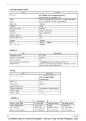
...number of keypads Windows logo key Internal & external keyboard work simultaneously Battery Item Vendor & model name Battery Type Pack capacity Number of battery cell Package configuration Normal voltage Charge voltage LCD 14.1 inch Item Vendor... & model name Screen Diagonal (mm) Active Area (mm) Display resolution (pixels) Controller Intel® 855GME+ICH4 (TravelMate 4000/4500) Intel® 852GM+ICH4 (TravelMate 2300) ATI Mobility RADEON 9700 (optional for TravelMate...
...number of keypads Windows logo key Internal & external keyboard work simultaneously Battery Item Vendor & model name Battery Type Pack capacity Number of battery cell Package configuration Normal voltage Charge voltage LCD 14.1 inch Item Vendor... & model name Screen Diagonal (mm) Active Area (mm) Display resolution (pixels) Controller Intel® 855GME+ICH4 (TravelMate 4000/4500) Intel® 852GM+ICH4 (TravelMate 2300) ATI Mobility RADEON 9700 (optional for TravelMate...
Service Guide
Page 47
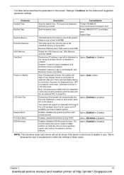
... Disabled Enables, disables the system boot from LAN (remote server). Parameter System Time System Date System Memory Extended Memory VGA Memory Fast Boot Power on battery power). Memory size is fixed to save power when AC is connected, the power on external video port. The system will support an automatic dimming...
... Disabled Enables, disables the system boot from LAN (remote server). Parameter System Time System Date System Memory Extended Memory VGA Memory Fast Boot Power on battery power). Memory size is fixed to save power when AC is connected, the power on external video port. The system will support an automatic dimming...

Service Guide
Page 56
... install memory-related drivers (XMS, EMS, DPMI) when you run the Phlash. 1. Copy the Phlash utilities to update the system BIOS flash ROM. If the battery pack does not contain enough power to run the Phlash utility. Then boot the system from the bootable diskette. Use the Phlash utility to the...
... install memory-related drivers (XMS, EMS, DPMI) when you run the Phlash. 1. Copy the Phlash utilities to update the system BIOS flash ROM. If the battery pack does not contain enough power to run the Phlash utility. Then boot the system from the bootable diskette. Use the Phlash utility to the...

Service Guide
Page 58
...Turn off the power to worry about mix them up. The image below . Mini PCI cover here also called RAM/Wireless cover. Remove the battery pack. Please pay attention to group the screws on the following : 1. There are twenty screws holding the bottom case to see these screws. ... and IO bezel 14 (Part number: 86.T23V7.010) (hightlight with the covers. Unplug the AC adapter and all peripherals. 2. IO Bezel Battery The screws that secure heatsink cover, MIni PCI cover and HDD cover are with yellow circle) Quantity 52 Chapter 3 download service manual and resetter printer...
...Turn off the power to worry about mix them up. The image below . Mini PCI cover here also called RAM/Wireless cover. Remove the battery pack. Please pay attention to group the screws on the following : 1. There are twenty screws holding the bottom case to see these screws. ... and IO bezel 14 (Part number: 86.T23V7.010) (hightlight with the covers. Unplug the AC adapter and all peripherals. 2. IO Bezel Battery The screws that secure heatsink cover, MIni PCI cover and HDD cover are with yellow circle) Quantity 52 Chapter 3 download service manual and resetter printer...

Service Guide
Page 59
M2.5*3 Detach the HDD module 1 (Part number: 86.T25V7.012) then you will see. M2.5*3 Remove the battery then you 1 (Part number: 86.T25V7.012) will see. Quantity Chapter 3 53 download service manual and resetter printer at http://printer1.blogspot.com Screw Type Location M2.5*6 Remove the IO bezel then 2 (Part number: 86.T23V7.010) you will see. M2.5*6 Remove the heatsink cover 1 (Part number: 86.T23V7.010) then you will see . M2.5*6 Remove the HDD cover then 1 (Part number: 86.T23V7.010) you will see .
M2.5*3 Detach the HDD module 1 (Part number: 86.T25V7.012) then you will see. M2.5*3 Remove the battery then you 1 (Part number: 86.T25V7.012) will see. Quantity Chapter 3 53 download service manual and resetter printer at http://printer1.blogspot.com Screw Type Location M2.5*6 Remove the IO bezel then 2 (Part number: 86.T23V7.010) you will see. M2.5*6 Remove the heatsink cover 1 (Part number: 86.T23V7.010) then you will see . M2.5*6 Remove the HDD cover then 1 (Part number: 86.T23V7.010) you will see .
Service Guide
Page 60
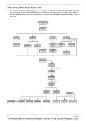
Start Battery *2 HDD Cover HDD Module *2 RAM/Wireless Cover Wireless LAN Card Memory CPU E*2 IO Bezel *2 Heatsink Cover ODD Module *2 back side *4 left/right side ODD Connector ...
Start Battery *2 HDD Cover HDD Module *2 RAM/Wireless Cover Wireless LAN Card Memory CPU E*2 IO Bezel *2 Heatsink Cover ODD Module *2 back side *4 left/right side ODD Connector ...

Service Guide
Page 62
Slide the battery latch as shown then remove the battery pack. 56 Chapter 3 download service manual and resetter printer at http://printer1.blogspot.com Unlock the battery lock. 2. Removing the Battery Pack 1.
Slide the battery latch as shown then remove the battery pack. 56 Chapter 3 download service manual and resetter printer at http://printer1.blogspot.com Unlock the battery lock. 2. Removing the Battery Pack 1.

Service Guide
Page 77
Connect the power adapter and check that power is supplied. 3. then check that power is supplied by the battery pack. Disconnect the power adapter and install the charged battery pack; If you suspect a power problem, see the appropriate power supply check in the following power sources: 1. Power System Check To verify the symptom of the following list: T "Check the Battery Pack" on the computer using each of the problem, power on page 72 Chapter 4 71 download service manual and resetter printer at http://printer1.blogspot.com Remove the battery pack. 2.
Connect the power adapter and check that power is supplied. 3. then check that power is supplied by the battery pack. Disconnect the power adapter and install the charged battery pack; If you suspect a power problem, see the appropriate power supply check in the following power sources: 1. Power System Check To verify the symptom of the following list: T "Check the Battery Pack" on the computer using each of the problem, power on page 72 Chapter 4 71 download service manual and resetter printer at http://printer1.blogspot.com Remove the battery pack. 2.

Service Guide
Page 78
...In Power Meter, confirm that has less than 7.5 Vdc after recharging, replace the battery. Repeat the steps 1 and 2, for Current Power Source and Total Battery Power Remaining are correct. 3. From Hardware: 1. To check the battery charge operation, use the touchpad, the pointer drifts on the screen for a ... computer. See the following : From Software: 1. If the voltage is working. 3. Re-install the battery pack. If the charge indicator still does not light up, replace the battery pack. After rebooting, run Syn touch driver. 2. Run utility with the PS/2 mouse function and check...
...In Power Meter, confirm that has less than 7.5 Vdc after recharging, replace the battery. Repeat the steps 1 and 2, for Current Power Source and Total Battery Power Remaining are correct. 3. From Hardware: 1. To check the battery charge operation, use the touchpad, the pointer drifts on the screen for a ... computer. See the following : From Software: 1. If the voltage is working. 3. Re-install the battery pack. If the charge indicator still does not light up, replace the battery pack. After rebooting, run Syn touch driver. 2. Run utility with the PS/2 mouse function and check...

Service Guide
Page 80
...Real time clock error Previous boot incomplete - Main board Enter Setup and see if fixed disk and drive A are properly identified. RTC battery Main baord "Load Default Settings" in BIOS Setup Utility. Default configuration used Invalid System Configuration Data Operating system not found FRU/Action in... Sequence See "Keyboard or Auxiliary Input Device Check" on page 70 RTC battery Run BIOS Setup Utility to reconfigure system time, then reboot system. Dikette drive Hard disk drive Main board 74 Chapter 4 download ...
...Real time clock error Previous boot incomplete - Main board Enter Setup and see if fixed disk and drive A are properly identified. RTC battery Main baord "Load Default Settings" in BIOS Setup Utility. Default configuration used Invalid System Configuration Data Operating system not found FRU/Action in... Sequence See "Keyboard or Auxiliary Input Device Check" on page 70 RTC battery Run BIOS Setup Utility to reconfigure system time, then reboot system. Dikette drive Hard disk drive Main board 74 Chapter 4 download ...

Service Guide
Page 81
Power source (battery pack and power adapter.) See "Power System Check" on page 71 Reconnect the LCD connector Hard disk drive LCD cable LCD inverter LCD Main board ... Reconnect the DIMM. But you can see POST on page 71 Ensure every connector is connected tightly and correctly. Reconnect the LCD connectors. Power source (battery pack and power adapter.) See "Power System Check" on an external CRT. shown on and a blinking cursor Ensure every connector is blank.
Power source (battery pack and power adapter.) See "Power System Check" on page 71 Reconnect the LCD connector Hard disk drive LCD cable LCD inverter LCD Main board ... Reconnect the DIMM. But you can see POST on page 71 Ensure every connector is connected tightly and correctly. Reconnect the LCD connectors. Power source (battery pack and power adapter.) See "Power System Check" on an external CRT. shown on and a blinking cursor Ensure every connector is blank.

Service Guide
Page 86
...Error LCD backlight doesn't work ). See "Power System Check" on . See "Power System Check" on page 71. Main board Power source (battery pack and power adapter). Action in the HDD. Action in Sequence Power-Related Symptoms Symptom / Error Power shuts down during operation The system cannot ...power-on page 71. Battery pack Power adapter CPU Main board In Windows XP operating system, hold and press the power switch for more than 4 seconds. Keyboard ...
...Error LCD backlight doesn't work ). See "Power System Check" on . See "Power System Check" on page 71. Main board Power source (battery pack and power adapter). Action in the HDD. Action in Sequence Power-Related Symptoms Symptom / Error Power shuts down during operation The system cannot ...power-on page 71. Battery pack Power adapter CPU Main board In Windows XP operating system, hold and press the power switch for more than 4 seconds. Keyboard ...
Service Guide
Page 87
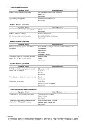
... portable computer. PC Card cannot be charged or discharged System hang during POST Action in Sequence See "Check the Battery Pack" on , but you hear two long beeps: "B--, B--" and the LCD is blank. Battery pack Main board ODD/HDD/FDD/RAM module Main board PCMCIA-Related Symptoms Symptom / Error System cannot detect... the PCMCIA slot is blocked Main board Memory-Related Symptoms Symptom / Error Memory count (size) appears different from the computer. Power-Related Symptoms Symptom / Error Battery can power on page 72.
... portable computer. PC Card cannot be charged or discharged System hang during POST Action in Sequence See "Check the Battery Pack" on , but you hear two long beeps: "B--, B--" and the LCD is blank. Battery pack Main board ODD/HDD/FDD/RAM module Main board PCMCIA-Related Symptoms Symptom / Error System cannot detect... the PCMCIA slot is blocked Main board Memory-Related Symptoms Symptom / Error Memory count (size) appears different from the computer. Power-Related Symptoms Symptom / Error Battery can power on page 72.


