
TravelMate 4010 Service Guide
Page 7
Table of Contents Chapter 1 System Specifications 1 Features 1 System Block Diagram 3 Board Layout 4 Top View 4 Bottom View 5 A TravelMate tour 7 Front Open View 7 Front Closed View 9 Left View 10 Right Panel 11 Rear Panel 12 Bottom Panel 13 Indicators 14 Using the Keyboard...Cear HDD Password SOP 48 Chapter 3 Machine Disassembly and Replacement 51 General Information 52 Before You Begin 52 Disassembly Procedure Flowchart 54 Removing the Battery Pack 56 Removing the HDD Module/the Memory and the Wireless LAN Card/the Thermal Module and the CPU/ODD Module and LCD Module 57...
Table of Contents Chapter 1 System Specifications 1 Features 1 System Block Diagram 3 Board Layout 4 Top View 4 Bottom View 5 A TravelMate tour 7 Front Open View 7 Front Closed View 9 Left View 10 Right Panel 11 Rear Panel 12 Bottom Panel 13 Indicators 14 Using the Keyboard...Cear HDD Password SOP 48 Chapter 3 Machine Disassembly and Replacement 51 General Information 52 Before You Begin 52 Disassembly Procedure Flowchart 54 Removing the Battery Pack 56 Removing the HDD Module/the Memory and the Wireless LAN Card/the Thermal Module and the CPU/ODD Module and LCD Module 57...
TravelMate 4010 Service Guide
Page 9
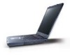
T Internal removable optical drive (AcerMedia bay) T Li-ion main battery pack Display T T T T T The TFT LCD panel providing a lare viewing area for selected models) Human-centric design and ergonomics T Rugged, yet extremely portable design T Stylish appearance T ...
T Internal removable optical drive (AcerMedia bay) T Li-ion main battery pack Display T T T T T The TFT LCD panel providing a lare viewing area for selected models) Human-centric design and ergonomics T Rugged, yet extremely portable design T Stylish appearance T ...
TravelMate 4010 Service Guide
Page 11
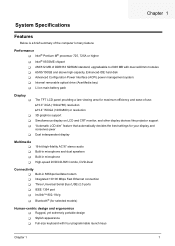
...4 5 6 SYSTEM 3 DOCKING 2 MINI-USB USB PORT USB PORT Page : 15 Page : 15 Page: 15 D USB2,3,5 USB0,1 USB4 PROJECT:Kestrel Series Acer Incorporated Size Document Number BLOCK DIAGRAM Date: Friday, June 04, 2004 7 Sheet 1 of 8 Rev A1A 35 Chapter 1 3 1 2 5VPCU 5V / ...2V B Page : 10 1.5V_S5 +1.5V AGP_VCC (+1.5V) 1.2VCCT VTT CPU CORE Page : 10 VCC_CORE VGA_CORE VGA CORE/VRAM 2.5V_VGA Page : 10 BATTERY C CHARGER Page : 10 BATTERY SELECT Page : 10 3 4 5 6 7 8 CLOCK GEN CYPRESS CY28346-2 Page : 10 Centrino BANIAS DORTHAN CELEROM-M CLOCK S/S INTEL Mobile_479 CPU Page ...
...4 5 6 SYSTEM 3 DOCKING 2 MINI-USB USB PORT USB PORT Page : 15 Page : 15 Page: 15 D USB2,3,5 USB0,1 USB4 PROJECT:Kestrel Series Acer Incorporated Size Document Number BLOCK DIAGRAM Date: Friday, June 04, 2004 7 Sheet 1 of 8 Rev A1A 35 Chapter 1 3 1 2 5VPCU 5V / ...2V B Page : 10 1.5V_S5 +1.5V AGP_VCC (+1.5V) 1.2VCCT VTT CPU CORE Page : 10 VCC_CORE VGA_CORE VGA CORE/VRAM 2.5V_VGA Page : 10 BATTERY C CHARGER Page : 10 BATTERY SELECT Page : 10 3 4 5 6 7 8 CLOCK GEN CYPRESS CY28346-2 Page : 10 Centrino BANIAS DORTHAN CELEROM-M CLOCK S/S INTEL Mobile_479 CPU Page ...

TravelMate 4010 Service Guide
Page 17
... the lid. Front Closed View # Icon Item Description 1 Speakers Left and right speakers deliver stereo audio output. 2 Power indicator Lights when the computer is on. 3 Battery indicator Lights when the battery is being charged 4 Bluetooth® Indicates that (optional) Bluetooth is communications enabled. 5 Wireless Indicates status of wireless LAN communi- Chapter 1 9
... the lid. Front Closed View # Icon Item Description 1 Speakers Left and right speakers deliver stereo audio output. 2 Power indicator Lights when the computer is on. 3 Battery indicator Lights when the battery is being charged 4 Bluetooth® Indicates that (optional) Bluetooth is communications enabled. 5 Wireless Indicates status of wireless LAN communi- Chapter 1 9

TravelMate 4010 Service Guide
Page 21
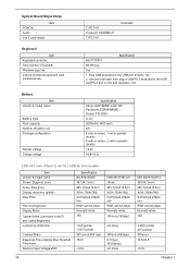
Bottom Panel # Item Description 1 Cooling fan Helps keep the computer cool. Chapter 1 13 Note: Do not cover or obstruct the opening of the fan. 2 Battery lock Locks the battery in place. 3 Memory compartment Houses the computer's main memory. 4 Hard disk bay Houses the computer's hard disk (secured by a screw). 5 Battery release latch Unlatches the battery to remove the battery pack. 6 Battery bay Houses the computer's battery pack.
Bottom Panel # Item Description 1 Cooling fan Helps keep the computer cool. Chapter 1 13 Note: Do not cover or obstruct the opening of the fan. 2 Battery lock Locks the battery in place. 3 Memory compartment Houses the computer's main memory. 4 Hard disk bay Houses the computer's hard disk (secured by a screw). 5 Battery release latch Unlatches the battery to remove the battery pack. 6 Battery bay Houses the computer's battery pack.

TravelMate 4010 Service Guide
Page 22
Num lock Lights when Num Lock is activated. Indicates the status of wireless LAN communication. Battery Lights up when the computer is on the front panel. Media Activity Bluetooh Wireless LAN Power Lights when the disc or AcerMedia is activated. Lights up when the battery is activated. Icon Function Caps lock Description Lights when Caps Lock is being charged. 14 Chapter 1 Indicates the status of Bluetooth communication. Indicators The computer has three easy-to-read status icons on the upper-right above the keyboard, and four on .
Num lock Lights when Num Lock is activated. Indicates the status of wireless LAN communication. Battery Lights up when the computer is on the front panel. Media Activity Bluetooh Wireless LAN Power Lights when the disc or AcerMedia is activated. Lights up when the battery is activated. Icon Function Caps lock Description Lights when Caps Lock is being charged. 14 Chapter 1 Indicates the status of Bluetooth communication. Indicators The computer has three easy-to-read status icons on the upper-right above the keyboard, and four on .
TravelMate 4010 Service Guide
Page 38
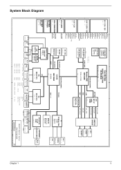
System Board Major Chips Item PCMCIA Audio 3-in-1 card reader Keyboard Item Keyboard controller Total number of battery cell Package configuration Normal voltage Charge voltage Specification Sanyo 4UR18650F-2-QC140 Panasonic CGR-B/8B5AE Simplo 916-3020 Li-ion 2000mAh/ 4400 mAh 4/8 ...keyboard to the USB port directly: Yes 2. Plug USB keyboard to the USB port/PS 2 port on the port replicator: Yes Battery Item Vendor & model name Battery Type Pack capacity Number of keypads Windows logo key Internal & external keyboard work simultaneously TI PC7411 Conexant CX20468-31 TI PC7411 Controller ...
System Board Major Chips Item PCMCIA Audio 3-in-1 card reader Keyboard Item Keyboard controller Total number of battery cell Package configuration Normal voltage Charge voltage Specification Sanyo 4UR18650F-2-QC140 Panasonic CGR-B/8B5AE Simplo 916-3020 Li-ion 2000mAh/ 4400 mAh 4/8 ...keyboard to the USB port directly: Yes 2. Plug USB keyboard to the USB port/PS 2 port on the port replicator: Yes Battery Item Vendor & model name Battery Type Pack capacity Number of keypads Windows logo key Internal & external keyboard work simultaneously TI PC7411 Conexant CX20468-31 TI PC7411 Controller ...
TravelMate 4010 Service Guide
Page 47
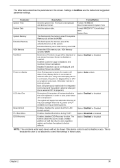
... or auto. Option: Enabled or Disabled NOTE: The sub-items under each device will be shown if the device control is connected, the power on battery power). Option: Auto or Both Determines if the system will be in the system. Option: Enabled or Disabled Enables, disables Boot Menu during POST. Settings...
... or auto. Option: Enabled or Disabled NOTE: The sub-items under each device will be shown if the device control is connected, the power on battery power). Option: Auto or Both Determines if the system will be in the system. Option: Enabled or Disabled Enables, disables Boot Menu during POST. Settings...
TravelMate 4010 Service Guide
Page 56
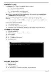
NOTE: Please use the AC adaptor power supply when you use the Phlash utility. If the battery pack does not contain enough power to run the Phlash utility. Copy the Phlash utilities to enter BIOS. 3. Cear BIOS Password SOP 1. Get master password. ...
NOTE: Please use the AC adaptor power supply when you use the Phlash utility. If the battery pack does not contain enough power to run the Phlash utility. Copy the Phlash utilities to enter BIOS. 3. Cear BIOS Password SOP 1. Get master password. ...

TravelMate 4010 Service Guide
Page 60
...to remove the HDD, the heatsink cover to the system and all power and signal cables from the system. 3. The image below . IO Bezel Battery The screws that secure heatsink cover, MIni PCI cover and HDD cover are with yellow circle) 52 Quantity Chapter 3 However, please notice that you ...disassemble the system for your reference. You may have to secure bottom case and upper case are inside the system. Remove the battery pack. Unplug the AC adapter and all peripherals. 2. NOTE: The screws used to group the screws on the following : 1. Please pay attention to...
...to remove the HDD, the heatsink cover to the system and all power and signal cables from the system. 3. The image below . IO Bezel Battery The screws that secure heatsink cover, MIni PCI cover and HDD cover are with yellow circle) 52 Quantity Chapter 3 However, please notice that you ...disassemble the system for your reference. You may have to secure bottom case and upper case are inside the system. Remove the battery pack. Unplug the AC adapter and all peripherals. 2. NOTE: The screws used to group the screws on the following : 1. Please pay attention to...

TravelMate 4010 Service Guide
Page 61
M2.5*6 Remove the heatsink cover 1 (Part number: 86.T23V7.010) then you will see. M2.5*3 Remove the battery then you 1 (Part number: 86.T25V7.012) will see. Screw Type Location M2.5*6 Remove the IO bezel then 2 (Part number: 86.T23V7.010) you will see. Quantity Chapter 3 53 M2.5*6 Remove the HDD cover then 1 (Part number: 86.T23V7.010) you will see . M2.5*3 Detach the HDD module 1 (Part number: 86.T25V7.012) then you will see .
M2.5*6 Remove the heatsink cover 1 (Part number: 86.T23V7.010) then you will see. M2.5*3 Remove the battery then you 1 (Part number: 86.T25V7.012) will see. Screw Type Location M2.5*6 Remove the IO bezel then 2 (Part number: 86.T23V7.010) you will see. Quantity Chapter 3 53 M2.5*6 Remove the HDD cover then 1 (Part number: 86.T23V7.010) you will see . M2.5*3 Detach the HDD module 1 (Part number: 86.T25V7.012) then you will see .
TravelMate 4010 Service Guide
Page 62
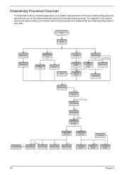
..., then disassemble the inside assembly frame in -1 Cover *4 Speaker Set B*2 Modem Board Upper Case Assembly Touchpad Touchpad Bracket B*2 Bluetooth Module Touchpad Board 54 Chapter 3 Start Battery *2 HDD Cover HDD Module *2 RAM/Wireless Cover Wireless LAN Card Memory CPU E*2 IO Bezel *2 Heatsink Cover ODD Module *2 back side *4 left/right side ODD Connector...
..., then disassemble the inside assembly frame in -1 Cover *4 Speaker Set B*2 Modem Board Upper Case Assembly Touchpad Touchpad Bracket B*2 Bluetooth Module Touchpad Board 54 Chapter 3 Start Battery *2 HDD Cover HDD Module *2 RAM/Wireless Cover Wireless LAN Card Memory CPU E*2 IO Bezel *2 Heatsink Cover ODD Module *2 back side *4 left/right side ODD Connector...

TravelMate 4010 Service Guide
Page 64
Removing the Battery Pack 1. Slide the battery latch as shown then remove the battery pack. 56 Chapter 3 Unlock the battery lock. 2.
Removing the Battery Pack 1. Slide the battery latch as shown then remove the battery pack. 56 Chapter 3 Unlock the battery lock. 2.

TravelMate 4010 Service Guide
Page 79
Connect the power adapter and check that power is supplied. 3. then check that power is supplied by the battery pack. If you suspect a power problem, see the appropriate power supply check in the following power sources: 1. Power System Check To verify the symptom of the following list: T "Check the Battery Pack" on the computer using each of the problem, power on page 72 Chapter 4 71 Remove the battery pack. 2. Disconnect the power adapter and install the charged battery pack;
Connect the power adapter and check that power is supplied. 3. then check that power is supplied by the battery pack. If you suspect a power problem, see the appropriate power supply check in the following power sources: 1. Power System Check To verify the symptom of the following list: T "Check the Battery Pack" on the computer using each of the problem, power on page 72 Chapter 4 71 Remove the battery pack. 2. Disconnect the power adapter and install the charged battery pack;

TravelMate 4010 Service Guide
Page 80
...following actions one at a time to the touchpad pointer. This helps you use a discharged battery pack or a battery pack that if the parameters shown in the screen for both battery and adapter. 4. Re-install the battery pack. For example, run Tracking Pad PS2 Mode Driver. If the the PS/2 mouse does...the main board to switch board FPC is applied to correct the problem. If the charge indicator still does not light up , replace the battery pack. Check out the Power Management in the computer. Power off the computer. 2. No service actions are pulese. If the FFC on ...
...following actions one at a time to the touchpad pointer. This helps you use a discharged battery pack or a battery pack that if the parameters shown in the screen for both battery and adapter. 4. Re-install the battery pack. For example, run Tracking Pad PS2 Mode Driver. If the the PS/2 mouse does...the main board to switch board FPC is applied to correct the problem. If the charge indicator still does not light up , replace the battery pack. Check out the Power Management in the computer. Power off the computer. 2. No service actions are pulese. If the FFC on ...

TravelMate 4010 Service Guide
Page 82
...System Configuration Data Operating system not found FRU/Action in Sequence See "Keyboard or Auxiliary Input Device Check" on page 70 RTC battery Run BIOS Setup Utility to reconfigure system time, then reboot system. Main board "Load Default Settings" in BIOS Setup Utility. Dikette ... Chapter 4 Main board Enter Setup and see if fixed disk and drive A are properly identified. RTC battery Run BIOS Setup Utility to reconfigure system, then reboot system. RTC battery Main baord "Load Default Settings" in BIOS Setup Utility. Default configuration used Real time clock error Previous...
...System Configuration Data Operating system not found FRU/Action in Sequence See "Keyboard or Auxiliary Input Device Check" on page 70 RTC battery Run BIOS Setup Utility to reconfigure system time, then reboot system. Main board "Load Default Settings" in BIOS Setup Utility. Dikette ... Chapter 4 Main board Enter Setup and see if fixed disk and drive A are properly identified. RTC battery Run BIOS Setup Utility to reconfigure system, then reboot system. RTC battery Main baord "Load Default Settings" in BIOS Setup Utility. Default configuration used Real time clock error Previous...

TravelMate 4010 Service Guide
Page 83
... turns off and LCD is blank. Error Message List No beep Error Messages FRU/Action in Sequence Power-on and LCD is blank. Power source (battery pack and power adapter.) See "Power System Check" on page 71 Reconnect the LCD connector Hard disk drive LCD cable LCD inverter LCD Main board... connected tightly and correctly. Reconnect the LCD connectors. LCD cable LCD inverter LCD Main board Power-on indicator turns on LCD during POST. Power source (battery pack and power adapter.) See "Power System Check" on page 71 Ensure every connector is connected tightly and correctly.
... turns off and LCD is blank. Error Message List No beep Error Messages FRU/Action in Sequence Power-on and LCD is blank. Power source (battery pack and power adapter.) See "Power System Check" on page 71 Reconnect the LCD connector Hard disk drive LCD cable LCD inverter LCD Main board... connected tightly and correctly. Reconnect the LCD connectors. LCD cable LCD inverter LCD Main board Power-on indicator turns on LCD during POST. Power source (battery pack and power adapter.) See "Power System Check" on page 71 Ensure every connector is connected tightly and correctly.
TravelMate 4010 Service Guide
Page 88
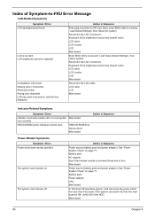
...board 80 Chapter 4 Keyboard (if the brightness function key doesn't work ). See "Power System Check" on page 71. Reconnect the LCD connectors. Battery pack AC adapter See if the thermal module is OK. Keyboard (if the brightness function key doesn't work ). LCD cable LCD inverter LCD Main board... LCD screen Missing pels in characters Abnormal screen Wrong color displayed LCD has extra horizontal or vertical lines displayed. Action in the HDD. Battery pack Power adapter CPU Main board In Windows XP operating system, hold and press the power switch for more than 4 seconds. Verify ...
...board 80 Chapter 4 Keyboard (if the brightness function key doesn't work ). See "Power System Check" on page 71. Reconnect the LCD connectors. Battery pack AC adapter See if the thermal module is OK. Keyboard (if the brightness function key doesn't work ). LCD cable LCD inverter LCD Main board... LCD screen Missing pels in characters Abnormal screen Wrong color displayed LCD has extra horizontal or vertical lines displayed. Action in the HDD. Battery pack Power adapter CPU Main board In Windows XP operating system, hold and press the power switch for more than 4 seconds. Verify ...
TravelMate 4010 Service Guide
Page 89
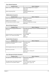
Battery pack Main board ODD/HDD/FDD/RAM module Main board PCMCIA-Related Symptoms Symptom / Error System cannot detect the... in Sequence Power option in Windows XP Hard disk drive Main board Driver of the portable computer. Power-Related Symptoms Symptom / Error Battery can power on page 72. Internal speakers make noise or emit no sound comes from actual size. System can 't be inserted or... standby mode after closing the lid of Power Option Properties Lid close switch in Sequence See "Check the Battery Pack" on , but you hear two long beeps: "B--, B--" and the LCD is damaged.
Battery pack Main board ODD/HDD/FDD/RAM module Main board PCMCIA-Related Symptoms Symptom / Error System cannot detect the... in Sequence Power option in Windows XP Hard disk drive Main board Driver of the portable computer. Power-Related Symptoms Symptom / Error Battery can power on page 72. Internal speakers make noise or emit no sound comes from actual size. System can 't be inserted or... standby mode after closing the lid of Power Option Properties Lid close switch in Sequence See "Check the Battery Pack" on , but you hear two long beeps: "B--, B--" and the LCD is damaged.

TravelMate 4010 Service Guide
Page 90
... if the system resumes from standby mode LCD cover switch after opening the lid of the portable computer. Check if the battery is low. Reconnect hard disk/CD-ROM drives/FDD or other peripherals. Main board Press Fn+F5, LCD/CRT/Both display ...Setup defaults", then reboot system. Touchpad does not work correctly. Main board Battery fuel gauge in Sequence The system doesn't resume from hibernation/ standby mode. Refresh battery (continue use battery until power off, then charge battery). Battery pack Main board System hangs intermittently. Main board Peripheral-Related Symptoms Symptom ...
... if the system resumes from standby mode LCD cover switch after opening the lid of the portable computer. Check if the battery is low. Reconnect hard disk/CD-ROM drives/FDD or other peripherals. Main board Press Fn+F5, LCD/CRT/Both display ...Setup defaults", then reboot system. Touchpad does not work correctly. Main board Battery fuel gauge in Sequence The system doesn't resume from hibernation/ standby mode. Refresh battery (continue use battery until power off, then charge battery). Battery pack Main board System hangs intermittently. Main board Peripheral-Related Symptoms Symptom ...


