
TravelMate 3000 Service Guide
Page 57
Remove the three screws that secures the function key board. 9. Disconnect the function key board FFC from the mainboard. 3. Chapter 3 51 Disconnect the LCD cable from the function key board. 8. Pull the wireless antenna out. 11. Pull the left hinge up and slide it out as show . 6. Remove the screw ... key board from the main unit. Disconnect the function key board FFC from the mainboard. 4. Disconnect the touchpad board FFC from the mainboard. 2. Detach the LCD module from the left and right hinge cover. 5. Seperate the...
Remove the three screws that secures the function key board. 9. Disconnect the function key board FFC from the mainboard. 3. Chapter 3 51 Disconnect the LCD cable from the function key board. 8. Pull the wireless antenna out. 11. Pull the left hinge up and slide it out as show . 6. Remove the screw ... key board from the main unit. Disconnect the function key board FFC from the mainboard. 4. Disconnect the touchpad board FFC from the mainboard. 2. Detach the LCD module from the left and right hinge cover. 5. Seperate the...

TravelMate 3000 Service Guide
Page 61
...Pull the inverter board out. 6. Disconnect the LCD cable from the cover assembly. 11. Remove the four screws that the bezel is fragile. Please note that secure the LCD. 10. Remove the LCD from the inverter board. 8. Chapter 3 55 Disconnect the LVDS cable from left to follow the following disassembly pictures ... Remove the six screw pads. 2. Remove the six screws that secure the wireless antenna. Tear off the tape on the wireless antenna cable. 12. Need to right. 4. Remvoe the four screws that secure the LCD bezel. 3. Pull the bezel a little bit forward that paralleled...
...Pull the inverter board out. 6. Disconnect the LCD cable from the cover assembly. 11. Remove the four screws that the bezel is fragile. Please note that secure the LCD. 10. Remove the LCD from the inverter board. 8. Chapter 3 55 Disconnect the LVDS cable from left to follow the following disassembly pictures ... Remove the six screw pads. 2. Remove the six screws that secure the wireless antenna. Tear off the tape on the wireless antenna cable. 12. Need to right. 4. Remvoe the four screws that secure the LCD bezel. 3. Pull the bezel a little bit forward that paralleled...

TravelMate 3000 Service Guide
Page 62
Remove the wireless antenna from the LCD. 21. Remove the left LCD bracket. 15. Remove the two screws that secure the left LCD bracket from the LCD. 18. Turn the LCD back. 19. Disconnect the LCD cable from the cover assembly. 14. Remove the two screws that secure the right LCD bracket. 17. Tear off the tape on theLCD cable. 20. This completes the LCD disassembly. 56 Chapter 3 13. Remove the right LCD bracket from the LCD. 16.
Remove the wireless antenna from the LCD. 21. Remove the left LCD bracket. 15. Remove the two screws that secure the left LCD bracket from the LCD. 18. Turn the LCD back. 19. Disconnect the LCD cable from the cover assembly. 14. Remove the two screws that secure the right LCD bracket. 17. Tear off the tape on theLCD cable. 20. This completes the LCD disassembly. 56 Chapter 3 13. Remove the right LCD bracket from the LCD. 16.
TravelMate 3000 Service Guide
Page 70
... adapter.) See "Power System Check" on page 60 Reconnect the LCD connector Hard disk drive LCD cable LCD inverter LCD Main board Power-on indicator turns on and a blinking cursor Ensure every connector is blank. LCD cable LCD inverter LCD Main board Power-on indicator turns on and LCD is connected tightly and correctly. shown on an external CRT. Main...
... adapter.) See "Power System Check" on page 60 Reconnect the LCD connector Hard disk drive LCD cable LCD inverter LCD Main board Power-on indicator turns on and a blinking cursor Ensure every connector is blank. LCD cable LCD inverter LCD Main board Power-on indicator turns on and LCD is connected tightly and correctly. shown on an external CRT. Main...

TravelMate 3000 Service Guide
Page 75
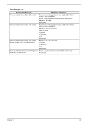
... / Error Power shuts down during operation The system cannot power-on page 60. Action in the HDD. LCD cable LCD inverter LCD Main board Reconnect the LCD cable LCD cable LCD Main board Indicator-Related Symptoms Symptom / Error Indicator incorrectly remains off or on, but system Main board runs...can power off . See "Power System Check" on page 60. Next, enter BIOS utility to CRT port. Reconnect the LCD connectors. LCD cable LCD inverter LCD Main board Enter BIOS Utility to execute "Load Setup Default Settings", then reboot system. Verify OS in Sequence Power source ...
... / Error Power shuts down during operation The system cannot power-on page 60. Action in the HDD. LCD cable LCD inverter LCD Main board Reconnect the LCD cable LCD cable LCD Main board Indicator-Related Symptoms Symptom / Error Indicator incorrectly remains off or on, but system Main board runs...can power off . See "Power System Check" on page 60. Next, enter BIOS utility to CRT port. Reconnect the LCD connectors. LCD cable LCD inverter LCD Main board Enter BIOS Utility to execute "Load Setup Default Settings", then reboot system. Verify OS in Sequence Power source ...

TravelMate 3000 Service Guide
Page 77
...to execute "Load Default Settings" then reboot the system. Connect AC adapter then check if the system resumes from standby mode LCD cover switch after opening the lid of the portable computer. Reconnect hard disk/CD-ROM drives. Main board Peripheral-Related Symptoms ... match the installed devices. External display does not work correctly Print problems. Parallel port device problems Action in Sequence Reconnect the keyboard cable. Touchpad board Main board 71 Chapter 4 Power Management-Related Symptoms Symptom / Error Action in Windows doesn't go higher than 90%....
...to execute "Load Default Settings" then reboot the system. Connect AC adapter then check if the system resumes from standby mode LCD cover switch after opening the lid of the portable computer. Reconnect hard disk/CD-ROM drives. Main board Peripheral-Related Symptoms ... match the installed devices. External display does not work correctly Print problems. Parallel port device problems Action in Sequence Reconnect the keyboard cable. Touchpad board Main board 71 Chapter 4 Power Management-Related Symptoms Symptom / Error Action in Windows doesn't go higher than 90%....

TravelMate 3000 Service Guide
Page 88
21 : 21 : : 22 8 5 9 : 7 : 9 23 9 22 : 3 6 4 23 2 Item Description 1 LCD cover assy 2 LCD bezel assy(TU) 3 INV module(PI) ED1 4 Hinge BKT-L (AU) 5 HInge BKT_R 6 Cable assy AUO-12.1"WXGA 7 LCD(TFT) 12.1" B121EW01 V1(WXGA) STN B/S 8 Screw M2.0*2.5(NI)(NYLOK) 9 Screw M2.0*5-I(NBI)(NYLOK)D4 T0.8 10 LCD Bezel rubber Q'ty 1 1 1 1 1 1 1 2 8 4 82 Chapter 6
21 : 21 : : 22 8 5 9 : 7 : 9 23 9 22 : 3 6 4 23 2 Item Description 1 LCD cover assy 2 LCD bezel assy(TU) 3 INV module(PI) ED1 4 Hinge BKT-L (AU) 5 HInge BKT_R 6 Cable assy AUO-12.1"WXGA 7 LCD(TFT) 12.1" B121EW01 V1(WXGA) STN B/S 8 Screw M2.0*2.5(NI)(NYLOK) 9 Screw M2.0*5-I(NBI)(NYLOK)D4 T0.8 10 LCD Bezel rubber Q'ty 1 1 1 1 1 1 1 2 8 4 82 Chapter 6


