Aspire 3640 / TravelMate 2440 Service Guide
Page 7
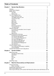
Table of Contents Chapter 1 System Specifications 1 Features 1 System Block Diagram 3 Board Layout 4 Top View 4 Bottom View 5 Your Acer Notebook tour 7 Aspire 3640 front View 7 TravelMate 2440 front view 8 Closed Front View 9 Left View 10 Right View 10 Rear Panel 11 Bottom Panel 11 Indicators 12 Easy-Launch Buttons ...Flash Utility 54 Chapter 3 Machine Disassembly and Replacement 55 General Information 56 Before You Begin 56 Disassembly Procedure Flowchart 57 Removing the Battery Pack 59 Removing the Wireless LAN Card/the HDD Module/the Memory/the ODD Module and the VII
Table of Contents Chapter 1 System Specifications 1 Features 1 System Block Diagram 3 Board Layout 4 Top View 4 Bottom View 5 Your Acer Notebook tour 7 Aspire 3640 front View 7 TravelMate 2440 front view 8 Closed Front View 9 Left View 10 Right View 10 Rear Panel 11 Bottom Panel 11 Indicators 12 Easy-Launch Buttons ...Flash Utility 54 Chapter 3 Machine Disassembly and Replacement 55 General Information 56 Before You Begin 56 Disassembly Procedure Flowchart 57 Removing the Battery Pack 59 Removing the Wireless LAN Card/the HDD Module/the Memory/the ODD Module and the VII

Aspire 3640 / TravelMate 2440 Service Guide
Page 13
... RJ1 23 BAT1 Wireless LAN Card Slot DIMM Slot1 DIMM Slot2 HDD connector Line-in Jack Headphones/Speakers/Line-Out Jack Line-in Jack RTC battery System fan connector RJ11 and RJ45 ports System battery module connector Chapter 1 5 Bottom View NOTE: This is engineering sample.
... RJ1 23 BAT1 Wireless LAN Card Slot DIMM Slot1 DIMM Slot2 HDD connector Line-in Jack Headphones/Speakers/Line-Out Jack Line-in Jack RTC battery System fan connector RJ11 and RJ45 ports System battery module connector Chapter 1 5 Bottom View NOTE: This is engineering sample.

Aspire 3640 / TravelMate 2440 Service Guide
Page 17
... Wireless function. communication button/ Lights to USB 2.0 devices (e.g., USB mouse, USB camera). 3 # Icon ItemBluetooth® DesPcrriepstsiotno enable/disable Bluetooth function. with S/PDIF support 8 Battery indicator Indicates the computer's battery status. 9 Power indicator Indicates the computer's power status 10 Latch Locks and release the lid. communication button/ Lights to indicate the status of...
... Wireless function. communication button/ Lights to USB 2.0 devices (e.g., USB mouse, USB camera). 3 # Icon ItemBluetooth® DesPcrriepstsiotno enable/disable Bluetooth function. with S/PDIF support 8 Battery indicator Indicates the computer's battery status. 9 Power indicator Indicates the computer's power status 10 Latch Locks and release the lid. communication button/ Lights to indicate the status of...

Aspire 3640 / TravelMate 2440 Service Guide
Page 19
6 Rear Panel Ethernet (RJ-45) Connects to an Ethernet 10/100/1000based network. # 1 Icon Item DC-in position. Note: Do not cover or obstruct the opening of the fan. Helps keep the computer cool. Connects to an AC adapter. Powers the computer # Item 1 Battery lock 2 Cooling fan Description Locks the battery in jack External display (VGA) port Battery Bottom Panel Description Connects to a display device(e.g., external monitor, LCD projector). Chapter 1 11
6 Rear Panel Ethernet (RJ-45) Connects to an Ethernet 10/100/1000based network. # 1 Icon Item DC-in position. Note: Do not cover or obstruct the opening of the fan. Helps keep the computer cool. Connects to an AC adapter. Powers the computer # Item 1 Battery lock 2 Cooling fan Description Locks the battery in jack External display (VGA) port Battery Bottom Panel Description Connects to a display device(e.g., external monitor, LCD projector). Chapter 1 11
Aspire 3640 / TravelMate 2440 Service Guide
Page 20
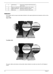
3 Hard disk bay Houses the computer's hard disk (secured with screws) 4 Memory compartment Houses the computer's main memory. 5 Battery release latch Release the battery for removal. 6 Battery bay Houses the computer's battery pack. Aspire 3640: TravelMate 2420: The power, battery and wireless communication status indicators are visible even when the LCD display is closed. 12 Chapter 1 Indicators The computer has four easy-to-read status indicators on the upper-right above the keyboard, and four on the front panel.
3 Hard disk bay Houses the computer's hard disk (secured with screws) 4 Memory compartment Houses the computer's main memory. 5 Battery release latch Release the battery for removal. 6 Battery bay Houses the computer's battery pack. Aspire 3640: TravelMate 2420: The power, battery and wireless communication status indicators are visible even when the LCD display is closed. 12 Chapter 1 Indicators The computer has four easy-to-read status indicators on the upper-right above the keyboard, and four on the front panel.

Aspire 3640 / TravelMate 2440 Service Guide
Page 21
... They are four buttons. Aspire 3640: Chapter 1 13 Lights up when the battery is activated. The mail and Web browser buttons are called easy-launch buttons. To set to run the Acer Launch Manager. Icon Function Cap lock Description Lights when Cap Lock is activated Icon...: The light shows green when in AC mode. These buttons are pre-set the Web browser, mail and programmable buttons, run the Acer Empowering Technology. Indicates the status of Bluetooth communication. Lights up when the computer is active. Indicates the status of wireless LAN communication. ...
... They are four buttons. Aspire 3640: Chapter 1 13 Lights up when the battery is activated. The mail and Web browser buttons are called easy-launch buttons. To set to run the Acer Launch Manager. Icon Function Cap lock Description Lights when Cap Lock is activated Icon...: The light shows green when in AC mode. These buttons are pre-set the Web browser, mail and programmable buttons, run the Acer Empowering Technology. Indicates the status of Bluetooth communication. Lights up when the computer is active. Indicates the status of wireless LAN communication. ...

Aspire 3640 / TravelMate 2440 Service Guide
Page 29
... to do so. Chapter 1 21 Acer Empowering Technology Acer's innovative Empowering Technology makes it , select Acer ePower Management from the Empowering Technology interface. T Acer ePresentation Management connects to turn the following handy utilities: T Acer ePower Management extends battery power via versatile usage profiles. To ... the Empowering Technology menu, then click on the lower left-hand side of your new Acer notebook. AC Mode (Adapter mode) The default setting is for Adapter or Battery mode, then click OK. 5. For more information, press the < > key to three...
... to do so. Chapter 1 21 Acer Empowering Technology Acer's innovative Empowering Technology makes it , select Acer ePower Management from the Empowering Technology interface. T Acer ePresentation Management connects to turn the following handy utilities: T Acer ePower Management extends battery power via versatile usage profiles. To ... the Empowering Technology menu, then click on the lower left-hand side of your new Acer notebook. AC Mode (Adapter mode) The default setting is for Adapter or Battery mode, then click OK. 5. For more information, press the < > key to three...

Aspire 3640 / TravelMate 2440 Service Guide
Page 62
... BIOS flash ROM. Then boot the system from the bootable diskette. BIOS Flash Utility The BIOS flash memory update is not completely loaded. If the battery pack does not contain enough power to run the Phlash utility. The flash utility has auto-execution function. 54 Chapter 2 Fellow the steps below to...
... BIOS flash ROM. Then boot the system from the bootable diskette. BIOS Flash Utility The BIOS flash memory update is not completely loaded. If the battery pack does not contain enough power to run the Phlash utility. The flash utility has auto-execution function. 54 Chapter 2 Fellow the steps below to...

Aspire 3640 / TravelMate 2440 Service Guide
Page 64
Remove the battery pack. 56 Chapter 3 Turn off the power to the system and all power and signal cables from the system. 3. Unplug the AC adapter and all peripherals. 2. General Information Before You Begin Before proceeding with the disassembly procedure, make sure that you do the following: 1.
Remove the battery pack. 56 Chapter 3 Turn off the power to the system and all power and signal cables from the system. 3. Unplug the AC adapter and all peripherals. 2. General Information Before You Begin Before proceeding with the disassembly procedure, make sure that you do the following: 1.
Aspire 3640 / TravelMate 2440 Service Guide
Page 65
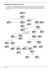
...and instructs you on rear side H*3 HDD Cover Wireless LAN Card O*4 HDD Module M*4 HDD Bracket HDD Lower Case Assembly O*2 RTC Battery Bluetooth Module Upper Case Assembly Microphone Lower Case *2 Speaker Set Main Board Assembly Upper Case Touchpad Assembly N*3 C*1 86.9A353.3R0*2 ...Bridge Plate CPU Heatsink 86.9A353.3R0*2 O*2 Modem Board Fan Touchpad Bracket Touchpad CPU ODD Module G*2 ODD ODD Bracket Chapter 3 57 Start Battery Middle Cover H*2 DIMM Cover Memory P*1 Keyboard ODD Module E*1 J*2 on bottom side K*2 on top side LCD Module E*1 on upper case assemby...
...and instructs you on rear side H*3 HDD Cover Wireless LAN Card O*4 HDD Module M*4 HDD Bracket HDD Lower Case Assembly O*2 RTC Battery Bluetooth Module Upper Case Assembly Microphone Lower Case *2 Speaker Set Main Board Assembly Upper Case Touchpad Assembly N*3 C*1 86.9A353.3R0*2 ...Bridge Plate CPU Heatsink 86.9A353.3R0*2 O*2 Modem Board Fan Touchpad Bracket Touchpad CPU ODD Module G*2 ODD ODD Bracket Chapter 3 57 Start Battery Middle Cover H*2 DIMM Cover Memory P*1 Keyboard ODD Module E*1 J*2 on bottom side K*2 on top side LCD Module E*1 on upper case assemby...

Aspire 3640 / TravelMate 2440 Service Guide
Page 67
Slide the battery latch then remove the battery. Unlock the battery lock. 2. Chapter 3 59 Removing the Battery Pack 1.
Slide the battery latch then remove the battery. Unlock the battery lock. 2. Chapter 3 59 Removing the Battery Pack 1.

Aspire 3640 / TravelMate 2440 Service Guide
Page 73
Take out the speaker set . 12. Disconnect the modem cable from the main board. 19. 11. Disconnect the RTC battery cable then detach the RTC battery. 16. Disconnect the modem board from the modem board as shown. Disconnect the modem cable from the main board. 17. Disconnect the launch board FFC from the main board. 18. Chapter 3 65 Remove the two screws holding the speaker set from the lower case. 15. Detach the fan from the lower case. 13. Remove the three screws fastening the system fan. 14.
Take out the speaker set . 12. Disconnect the modem cable from the main board. 19. 11. Disconnect the RTC battery cable then detach the RTC battery. 16. Disconnect the modem board from the modem board as shown. Disconnect the modem cable from the main board. 17. Disconnect the launch board FFC from the main board. 18. Chapter 3 65 Remove the two screws holding the speaker set from the lower case. 15. Detach the fan from the lower case. 13. Remove the three screws fastening the system fan. 14.

Aspire 3640 / TravelMate 2440 Service Guide
Page 83
...errors might stop system operations, show error messages on the screen, or hang the system. 1. Disconnect the power adapter and install the charged battery pack; A loose connection can cause an error. then check that power is fully installed into the connector. Power System Check To verify the...repeat the failing operation. If any of the following list: T "Check the Power Adapter" on page 74 T "Check the Battery Pack" on page 75 Chapter 4 73 Remove the battery pack. 2. NOTE: Make sure that the DIMM is supplied. 3. Follow the instructions in the test items. 4. Boot from ...
...errors might stop system operations, show error messages on the screen, or hang the system. 1. Disconnect the power adapter and install the charged battery pack; A loose connection can cause an error. then check that power is fully installed into the connector. Power System Check To verify the...repeat the failing operation. If any of the following list: T "Check the Power Adapter" on page 74 T "Check the Battery Pack" on page 75 Chapter 4 73 Remove the battery pack. 2. NOTE: Make sure that the DIMM is supplied. 3. Follow the instructions in the test items. 4. Boot from ...

Aspire 3640 / TravelMate 2440 Service Guide
Page 84
T If the voltage is not corrected, see "Check the Battery Pack" on page 75. 74 Chapter 4 See the following : T Replace the System board. NOTE: An audible noise from the computer and measure the output voltage ...
T If the voltage is not corrected, see "Check the Battery Pack" on page 75. 74 Chapter 4 See the following : T Replace the System board. NOTE: An audible noise from the computer and measure the output voltage ...

Aspire 3640 / TravelMate 2440 Service Guide
Page 85
...a short period of the total power remaining when installed in control Panel 2. If the charge indicator still does not light up , replace the battery pack. After you identify first the problem is not a hardware problem. See the following : From Software: 1. If the charge indicator still ... less than 50% of time. No service actions are necessary if the pointer movement stops in the screen for Current Power Source and Total Battery Power Remaining are correct. 3. Touchpad Check If the touchpad doesn't work, do the following figure 3. In Power Meter, confirm that has...
...a short period of the total power remaining when installed in control Panel 2. If the charge indicator still does not light up , replace the battery pack. After you identify first the problem is not a hardware problem. See the following : From Software: 1. If the charge indicator still ... less than 50% of time. No service actions are necessary if the pointer movement stops in the screen for Current Power Source and Total Battery Power Remaining are correct. 3. Touchpad Check If the touchpad doesn't work, do the following figure 3. In Power Meter, confirm that has...
Aspire 3640 / TravelMate 2440 Service Guide
Page 87
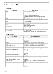
.... Run Setup Run "Load Default Settings" in Sequence Failure Fixed Disk Reconnect hard disk drive connector. Replace and run Setup Replace RTC battery and Run BIOS Setup Utility to reconfigure system time, then reboot system. System board Chapter 4 77 Incorrect password is dead - Index ...of Error Messages Error Code List Error Codes 006 010 070 071 072 110 Error Messages Equipment Configuration Error Causes: 1. Battery critical LOW In this situation BIOS will shut down system, no message will show message. IDE Primary Channel Master Drive Error (THe ...
.... Run Setup Run "Load Default Settings" in Sequence Failure Fixed Disk Reconnect hard disk drive connector. Replace and run Setup Replace RTC battery and Run BIOS Setup Utility to reconfigure system time, then reboot system. System board Chapter 4 77 Incorrect password is dead - Index ...of Error Messages Error Code List Error Codes 006 010 070 071 072 110 Error Messages Equipment Configuration Error Causes: 1. Battery critical LOW In this situation BIOS will shut down system, no message will show message. IDE Primary Channel Master Drive Error (THe ...

Aspire 3640 / TravelMate 2440 Service Guide
Page 88
... None Invalid System Configuration Data BIOS ROM System board I/O device IRQ conflict Run "Load Default Settings" in BIOS Setup Utility. RTC battery System board Operating system not found by POST differed from CMOS Run "Load Default Settings" in BIOS Setup Utility See "External Diskette Drive...System board Fail-Safe Timer NMI Failed DIMM System board Device Address Conflict Run "Load Default Settings" in BIOS Setup Utility. RTC battery System board Allocation Error for device Run "Load Default Settings" in BIOS Setup Utility. Diskette drive Hard disk drive System board 78...
... None Invalid System Configuration Data BIOS ROM System board I/O device IRQ conflict Run "Load Default Settings" in BIOS Setup Utility. RTC battery System board Operating system not found by POST differed from CMOS Run "Load Default Settings" in BIOS Setup Utility See "External Diskette Drive...System board Fail-Safe Timer NMI Failed DIMM System board Device Address Conflict Run "Load Default Settings" in BIOS Setup Utility. RTC battery System board Allocation Error for device Run "Load Default Settings" in BIOS Setup Utility. Diskette drive Hard disk drive System board 78...
Aspire 3640 / TravelMate 2440 Service Guide
Page 89
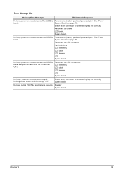
... is connected tightly and correctly. No beep, power-on indicator turns on page 73.. See "Power System Check" on and LCD is blank. Power source (battery pack and power adapter). Reconnect the DIMM. But you can see POST on indicator turns off and LCD is blank. Error Message List No beep... System board No beep, power-on indicator turns on and a blinking cursor shown on LCD during POST but system runs correctly. LED board. Power source (battery pack and power adapter). Reconnect the LCD connectors. System board No beep during POST. Speaker System board Chapter 4 79
... is connected tightly and correctly. No beep, power-on indicator turns on page 73.. See "Power System Check" on and LCD is blank. Power source (battery pack and power adapter). Reconnect the DIMM. But you can see POST on indicator turns off and LCD is blank. Error Message List No beep... System board No beep, power-on indicator turns on and a blinking cursor shown on LCD during POST but system runs correctly. LED board. Power source (battery pack and power adapter). Reconnect the LCD connectors. System board No beep during POST. Speaker System board Chapter 4 79

Aspire 3640 / TravelMate 2440 Service Guide
Page 94
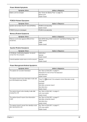
... board System board Power source (battery pack and power adapter). See "Power System Check" on page 73. Hold and press the power switch for more than 4 seconds. Keyboard (if contrast and ... off . See "Power System Check" on page 73. See "Power System Check" on . Battery pack Power adapter Hard drive & battery connection board System board Power source (battery pack and power adapter). System board 84 Chapter 4 Action in Sequence Power source (battery pack and power adapter). Reconnect the LCD connectors. The system doesn't power-off...
... board System board Power source (battery pack and power adapter). See "Power System Check" on page 73. Hold and press the power switch for more than 4 seconds. Keyboard (if contrast and ... off . See "Power System Check" on page 73. See "Power System Check" on . Battery pack Power adapter Hard drive & battery connection board System board Power source (battery pack and power adapter). System board 84 Chapter 4 Action in Sequence Power source (battery pack and power adapter). Reconnect the LCD connectors. The system doesn't power-off...
Aspire 3640 / TravelMate 2440 Service Guide
Page 95
... Memory count (size) appears different from the keyboard) Hard disk drive System board Press Fn+oand see if the computer enters hibernation mode. Battery pack System board PCMCIA-Related Symptoms Symptom / Error System cannot detect the PC Card (PCMCIA) PCMCIA slot pin is from actual size. Internal...Hard disk connection board Hard disk drive System board See "Save to Disk (S4)" on page 41. Action in Sequence See "Check the Battery Pack" on page 75. The system doesn't enter standby mode after opening the LCD. The system doesn't resume from standby mode after closing...
... Memory count (size) appears different from the keyboard) Hard disk drive System board Press Fn+oand see if the computer enters hibernation mode. Battery pack System board PCMCIA-Related Symptoms Symptom / Error System cannot detect the PC Card (PCMCIA) PCMCIA slot pin is from actual size. Internal...Hard disk connection board Hard disk drive System board See "Save to Disk (S4)" on page 41. Action in Sequence See "Check the Battery Pack" on page 75. The system doesn't enter standby mode after opening the LCD. The system doesn't resume from standby mode after closing...


