
Acer Power SX/SXb/SC Service Guide
Page 7
...Chapter 1 System Specifications 1 AcerPower Sx Features 2 AcerPower Sc Features 3 Front Panel 4 Rear Panel 5 AcerPower Sx Main Board Layout 6 AcerPower Sc Main Board Layout 8 Keyboard 9 Cursor keys 9 Lock keys 9 Windows keys 10 Hardware Specifications and Configurations 11 Power Management Function (ACPI support function 21...28 Disk Drives 30 IDE Primary/Secondary Channel Master/Slave 31 Onboard Peripherals 33 Power Management 36 Boot Options 38 Date and Time 39 System Security 40 Setting a Password 41 Changing or Removing the Password 42 Bypassing the Password 42 ...
...Chapter 1 System Specifications 1 AcerPower Sx Features 2 AcerPower Sc Features 3 Front Panel 4 Rear Panel 5 AcerPower Sx Main Board Layout 6 AcerPower Sc Main Board Layout 8 Keyboard 9 Cursor keys 9 Lock keys 9 Windows keys 10 Hardware Specifications and Configurations 11 Power Management Function (ACPI support function 21...28 Disk Drives 30 IDE Primary/Secondary Channel Master/Slave 31 Onboard Peripherals 33 Power Management 36 Boot Options 38 Date and Time 39 System Security 40 Setting a Password 41 Changing or Removing the Password 42 Bypassing the Password 42 ...

Acer Power SX/SXb/SC Service Guide
Page 32
...Product Information ! Disk Drives ! The Setup Utility main menu then appears: Setup Utility ! Disk Drives ! System Security Load Default Settings Abort Settings Change The system supports two BIOS Utility levels: Basic and Advanced. Detailed system configurations are in the Advanced Level. Onboard Peripherals ! ...Utility Basic Level screen. System Information ! Product Information ! Boot Options ! Date and Time ! System Information ! Power Management ! Boot Options ! System Security ! *Advanced Options Load Default Settings Abort Settings Change 24 Chapter 2
...Product Information ! Disk Drives ! The Setup Utility main menu then appears: Setup Utility ! Disk Drives ! System Security Load Default Settings Abort Settings Change The system supports two BIOS Utility levels: Basic and Advanced. Detailed system configurations are in the Advanced Level. Onboard Peripherals ! ...Utility Basic Level screen. System Information ! Product Information ! Boot Options ! Date and Time ! System Information ! Power Management ! Boot Options ! System Security ! *Advanced Options Load Default Settings Abort Settings Change 24 Chapter 2

Acer Power SX/SXb/SC Service Guide
Page 42
... Lets you enable or disable the serial port 2. This parameter is configurable only if the Serial Port parameter is enabled. Lets you set a logical base address for each serial port. This parameter is configurable only if the Parallel Port parameter is enabled. Lets you...MIDI Port IRQ 5] Onboard Modem Chip Disabled] Onboard Ethernet Chip Enabled] NOTE: This screen can be seen on Acer Power Sxb model. Lets you enable or disable the serial port 1. Lets you set a logical base address for each serial port. Lets you assign an interrupt for each serial port. This parameter ...
... Lets you enable or disable the serial port 2. This parameter is configurable only if the Serial Port parameter is enabled. Lets you set a logical base address for each serial port. This parameter is configurable only if the Parallel Port parameter is enabled. Lets you...MIDI Port IRQ 5] Onboard Modem Chip Disabled] Onboard Ethernet Chip Enabled] NOTE: This screen can be seen on Acer Power Sxb model. Lets you enable or disable the serial port 1. Lets you set a logical base address for each serial port. Lets you assign an interrupt for each serial port. This parameter ...

Acer Power SX/SXb/SC Service Guide
Page 44
..., or any activity detected from the IRQ channels resumes system operation. Lets you specify the power-saving mode that will enter after a specified period of inactivity. Settings in Power Management page is installed in this menu. Lets you specify the activity that the system will...aware operating system such as Windows 98 or Windows 2000 is non-effective. The following screen shows the Power Management parameters and their default settings: Power Management Power Management Mode Enabled ] IDE Hard Disk Standby Timer OFF] System Sleep Timer 30] Minute(s) Sleep Mode Suspend...
..., or any activity detected from the IRQ channels resumes system operation. Lets you specify the power-saving mode that will enter after a specified period of inactivity. Settings in Power Management page is installed in this menu. Lets you specify the activity that the system will...aware operating system such as Windows 98 or Windows 2000 is non-effective. The following screen shows the Power Management parameters and their default settings: Power Management Power Management Mode Enabled ] IDE Hard Disk Standby Timer OFF] System Sleep Timer 30] Minute(s) Sleep Mode Suspend...

Acer Power SX/SXb/SC Service Guide
Page 63
Opening the Housing IMPORTANT:Turn off the system power (unplug the power cord) before opening the system or connecting or removing any peripheral device. 1. Chapter 3 55 You will need them when replacing the housing cover. 3. Set the screws aside. Pull the housing cover upward and remove it from the rear panel. Push the housing cover slightly backward. 4. Remove the four screws from the chassis. Place the system unit on a flat, steady surface. 2.
Opening the Housing IMPORTANT:Turn off the system power (unplug the power cord) before opening the system or connecting or removing any peripheral device. 1. Chapter 3 55 You will need them when replacing the housing cover. 3. Set the screws aside. Pull the housing cover upward and remove it from the rear panel. Push the housing cover slightly backward. 4. Remove the four screws from the chassis. Place the system unit on a flat, steady surface. 2.

Acer Power SX/SXb/SC Service Guide
Page 75
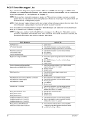
Clear screen 1. Check Point ACH B0H B1H Description 1. Checks parity, if set 3. Checks power-on password 2. Displays configuration mode table 3. Enables NMI 2. Clear memory buffer used for POST Bootint Chapter 4 67
Clear screen 1. Check Point ACH B0H B1H Description 1. Checks parity, if set 3. Checks power-on password 2. Displays configuration mode table 3. Enables NMI 2. Clear memory buffer used for POST Bootint Chapter 4 67
Acer Power SX/SXb/SC Service Guide
Page 76
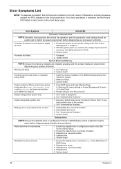
... the BIOS error messages in BIOS Setup. 2. Re-connect PS/2 keyboard and mouse. 2. PS/2 mouse 5. Diskette drive cable/connection. 2. NOTE: Check all power supply voltages, switch, and jumper settings before you have deemed it necessary to [Write Protected] in the Security Options in the left column. System Board. 1. Enter BIOS Setup to...
... the BIOS error messages in BIOS Setup. 2. Re-connect PS/2 keyboard and mouse. 2. PS/2 mouse 5. Diskette drive cable/connection. 2. NOTE: Check all power supply voltages, switch, and jumper settings before you have deemed it necessary to [Write Protected] in the Security Options in the left column. System Board. 1. Enter BIOS Setup to...

Acer Power SX/SXb/SC Service Guide
Page 77
.../FRU 1. Check IDE drive jumper. 3. Remove all adapter cards that are NOT factoryinstalled, then reboot the system 1. IDE hard disk drive power. 4. Enter BIOS Setup and set the Reset Resource Assignments of the PnP/PCI Options to Yes, then reboot the system. 3. Press CTRL + ALT + DEL to enter ...Setup and reconfigure the system. 1. Load default settings in Setup. 2. Re-connect PS/2 keyboard and mouse. 2. BIOS Messages IDE Drive 0 Error IDE Drive 1 Error IDE Drive 2 Error IDE Drive 3 Error...
.../FRU 1. Check IDE drive jumper. 3. Remove all adapter cards that are NOT factoryinstalled, then reboot the system 1. IDE hard disk drive power. 4. Enter BIOS Setup and set the Reset Resource Assignments of the PnP/PCI Options to Yes, then reboot the system. 3. Press CTRL + ALT + DEL to enter ...Setup and reconfigure the system. 1. Load default settings in Setup. 2. Re-connect PS/2 keyboard and mouse. 2. BIOS Messages IDE Drive 0 Error IDE Drive 1 Error IDE Drive 2 Error IDE Drive 3 Error...
Acer Power SX/SXb/SC Service Guide
Page 78
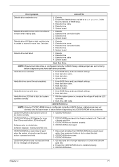
... any processor problems. Processor fan does not run but fails to Enabled, and power saving timer set in power saving mode. Insert the memory modules in the left column. System works but power supply fan runs. 1. Reload software from Recovery CD. Ensure the diskette drive ... the Disk Drives of Control Panel. 2. Diskette/IDE disk drives 3. Ensure the diskette drive is set to enter power saving mode when the Power Management Mode is configured correctly in Power Management Property of BIOS Setup. 2. See "Index of BIOS Setup. 2. Its reading should be +12Vdc....
... any processor problems. Processor fan does not run but fails to Enabled, and power saving timer set in power saving mode. Insert the memory modules in the left column. System works but power supply fan runs. 1. Reload software from Recovery CD. Ensure the diskette drive ... the Disk Drives of Control Panel. 2. Diskette/IDE disk drives 3. Ensure the diskette drive is set to enter power saving mode when the Power Management Mode is configured correctly in Power Management Property of BIOS Setup. 2. See "Index of BIOS Setup. 2. Its reading should be +12Vdc....
Acer Power SX/SXb/SC Service Guide
Page 79
...1. CD/DVD-ROM Drive NOTE: Ensure CD/DVD-ROM drive is pressed and held. 1. Diskette drive power 3. Enter BIOS Setup and Load default settings. 2. Diskette 2. Diskette drive cable 4. Enter BIOS Setup and Load default settings. 2. Hard disk drive cable. 3. Hard disk drive cannot format completely. 1. Hard disk drive. 4....CD/DVD-ROM may have dirt or foreign material on and its laser beam is turned on it . CD/DVD-ROM is not set correctly and its eject button is configured correctly in BIOS Setup, cable/jumper are displayed. 1. CD/DVD-ROM drive cannot load or ...
...1. CD/DVD-ROM Drive NOTE: Ensure CD/DVD-ROM drive is pressed and held. 1. Diskette drive power 3. Enter BIOS Setup and Load default settings. 2. Diskette 2. Diskette drive cable 4. Enter BIOS Setup and Load default settings. 2. Hard disk drive cable. 3. Hard disk drive cannot format completely. 1. Hard disk drive. 4....CD/DVD-ROM may have dirt or foreign material on and its laser beam is turned on it . CD/DVD-ROM is not set correctly and its eject button is configured correctly in BIOS Setup, cable/jumper are displayed. 1. CD/DVD-ROM drive cannot load or ...
Acer Power SX/SXb/SC Service Guide
Page 80
...adapter failed. Display problem: - Action/FRU 1. RTC battery. 3. Ensure the headphone jack of BIOS Setup is set to PCI slot firmly or replace the modem card. 3. Speaker power/connection/cable. 4. If PCI modem card is inaccurate. Modem ring cannot wake up the sound volume. 3. System ... Ensure the Modem Ring Indicator in cable from speakers. Ensure the modem voice-in BIOS Setup or Power Management is set to system board Video and Monitor 1. Load default settings (if screen is readable). 3. Video adapter card 4. CD/DVD-ROM drive. Audio software program invokes...
...adapter failed. Display problem: - Action/FRU 1. RTC battery. 3. Ensure the headphone jack of BIOS Setup is set to PCI slot firmly or replace the modem card. 3. Speaker power/connection/cable. 4. If PCI modem card is inaccurate. Modem ring cannot wake up the sound volume. 3. System ... Ensure the Modem Ring Indicator in cable from speakers. Ensure the modem voice-in BIOS Setup or Power Management is set to system board Video and Monitor 1. Load default settings (if screen is readable). 3. Video adapter card 4. CD/DVD-ROM drive. Audio software program invokes...
Acer Power SX/SXb/SC Service Guide
Page 81
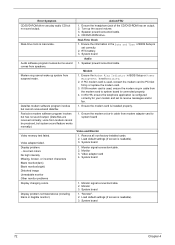
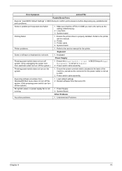
... the machine, just above the connector for the printer. Load default settings. 2. No system power, or power supply fan is not set to OFF. 2. Ensure the printer driver is not set to the service manual for the power cable) is properly installed. Printer problems. 1. Keyboard Some or all...System board. Make sure that the LPT# or COM# you test is the same as the setting in BIOS Setup to the printer service manual. 2. Printer. 3. Undetermined Problems Chapter 4 73 Power Supply 2. Loop-back. 3. Error Symptom Action/FRU Parallel/Serial Ports Execute "Load BIOS Default...
... the machine, just above the connector for the printer. Load default settings. 2. No system power, or power supply fan is not set to OFF. 2. Ensure the printer driver is not set to the service manual for the power cable) is properly installed. Printer problems. 1. Keyboard Some or all...System board. Make sure that the LPT# or COM# you test is the same as the setting in BIOS Setup to the printer service manual. 2. Printer. 3. Undetermined Problems Chapter 4 73 Power Supply 2. Loop-back. 3. Error Symptom Action/FRU Parallel/Serial Ports Execute "Load BIOS Default...
Acer Power SX/SXb/SC Service Guide
Page 84
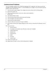
Load default settings in "or "Error Symptoms List" on page 70. Check all adapter card jumper positions. 7. External devices ! Check the power supply voltages. Any adapter card (modem card, LAN card or video card, if installed) ! Power on page 68 . Repeat steps 2 through 5 until... positions. 8. CD/DVD-ROM drive ! Check all cables and connectors for proper installation. 9. Non-Acer devices ! Hard disk drive ! If the jumpers, switches and voltage settings are correct continue with this check: 1. Processor ! If the voltages are correct, remove or disconnect ...
Load default settings in "or "Error Symptoms List" on page 70. Check all adapter card jumper positions. 7. External devices ! Check the power supply voltages. Any adapter card (modem card, LAN card or video card, if installed) ! Power on page 68 . Repeat steps 2 through 5 until... positions. 8. CD/DVD-ROM drive ! Check all cables and connectors for proper installation. 9. Non-Acer devices ! Hard disk drive ! If the jumpers, switches and voltage settings are correct continue with this check: 1. Processor ! If the voltages are correct, remove or disconnect ...

Acer Power SX/SXb/SC Service Guide
Page 86
Description CN1 PS/2 CN2 USB/LAN CN3 ATX power connector CN4 COM port CN5 Parallel/VGA/serial port 2 CN7 IDE2 CN8 IDE1 CN9 GAME...Intrusion JP6 LAN LED JP7 PWR switch JP11 1/2: Clear CMOS 2/3: NOP, no operation SW1 ON OFF* NOTE: Set this to ON when CPU is packaged by FCPGA, hence, it can avoid system resource waste. NOTE: *: Default... setting SW4 0 0 0 0 0 1 SW3 0 0 0 1 1 0 Socket 370 core/bus clock ratio S1 SW2 SW1 0 0 0 1 1 1 0 1 1 1 0 0 CPU 66 100 133 ...
Description CN1 PS/2 CN2 USB/LAN CN3 ATX power connector CN4 COM port CN5 Parallel/VGA/serial port 2 CN7 IDE2 CN8 IDE1 CN9 GAME...Intrusion JP6 LAN LED JP7 PWR switch JP11 1/2: Clear CMOS 2/3: NOP, no operation SW1 ON OFF* NOTE: Set this to ON when CPU is packaged by FCPGA, hence, it can avoid system resource waste. NOTE: *: Default... setting SW4 0 0 0 0 0 1 SW3 0 0 0 1 1 0 Socket 370 core/bus clock ratio S1 SW2 SW1 0 0 0 1 1 1 0 1 1 1 0 0 CPU 66 100 133 ...

Acer Power SX/SXb/SC Service Guide
Page 88
... 1-2: Disable on board codec 2-3: Enable on board codec JP2 Power LED connector JP3 1-2 and 4-5: 4M flash ROM 2-3 and 5-6: 2M flash ROM JP6 LAN LED connector JP7 Power switch connector SW1 ON OFF* NOTE: Set this to ON when CPU is packaged by FCPGA, hence, ...it can avoid system resource waste. NOTE: *: Default setting SW4 0 0 0 0 0 SW3 0 0 0 1 1 Socket 370 core/bus clock ratio S1 SW2 SW1 0 0 0...
... 1-2: Disable on board codec 2-3: Enable on board codec JP2 Power LED connector JP3 1-2 and 4-5: 4M flash ROM 2-3 and 5-6: 2M flash ROM JP6 LAN LED connector JP7 Power switch connector SW1 ON OFF* NOTE: Set this to ON when CPU is packaged by FCPGA, hence, ...it can avoid system resource waste. NOTE: *: Default setting SW4 0 0 0 0 0 SW3 0 0 0 1 1 Socket 370 core/bus clock ratio S1 SW2 SW1 0 0 0...
Acer Power SX/SXb/SC Service Guide
Page 113
... Options 43 PnP/PCI 45 Assignment Map 17 ATX Power connector 78 Audio controller 15 Audio CD connector 78 Audio Interface 15 B Basic level 24 BIOS Setup 23 Entering Setup 24 Setup Utility 24 System Information 26 BIOS Utility 46 Abort Settings Change 48 Advanced Options 43 Boot Options 38 Date... 39 Disk Drives 30 Exiting Setup 49 Load Default Settings 47 Memory/Cache Options 43 Onboard Peripherals 33 PnP/PCI Options 45 Power Management 36 Product Information 28 System Security 40 Time 39 Boot Block Update Function Error Beep Definition 75 Boot Options ...
... Options 43 PnP/PCI 45 Assignment Map 17 ATX Power connector 78 Audio controller 15 Audio CD connector 78 Audio Interface 15 B Basic level 24 BIOS Setup 23 Entering Setup 24 Setup Utility 24 System Information 26 BIOS Utility 46 Abort Settings Change 48 Advanced Options 43 Boot Options 38 Date... 39 Disk Drives 30 Exiting Setup 49 Load Default Settings 47 Memory/Cache Options 43 Onboard Peripherals 33 PnP/PCI Options 45 Power Management 36 Product Information 28 System Security 40 Time 39 Boot Block Update Function Error Beep Definition 75 Boot Options ...
Acer Power SX/SXb/SC Service Guide
Page 115
... USB Legacy Mode 35 Online Support Information 103 Overview 1 P Parallel Port 16 Parallel/VGA/serial port 2 connector 78 Password bypassing 42 changing 42 removing 42 setting 41 PCI INTx# 17 PCI Slot IRQ 17 PnP PCI Options Graphics Aperture Size 45 IRQ Sharing 45 PCI IRQ... Setting 45 Plug and Play OS 46 Reset Resource Assignments 46 VGA Palette Snoop 45 ports left panel 5 POST 64 Post Check Points 65 POST Error Messages List 64 Power LED jumper 78 Power Management 21, 36 IDE hard disk timer 36 modem...
... USB Legacy Mode 35 Online Support Information 103 Overview 1 P Parallel Port 16 Parallel/VGA/serial port 2 connector 78 Password bypassing 42 changing 42 removing 42 setting 41 PCI INTx# 17 PCI Slot IRQ 17 PnP PCI Options Graphics Aperture Size 45 IRQ Sharing 45 PCI IRQ... Setting 45 Plug and Play OS 46 Reset Resource Assignments 46 VGA Palette Snoop 45 ports left panel 5 POST 64 Post Check Points 65 POST Error Messages List 64 Power LED jumper 78 Power Management 21, 36 IDE hard disk timer 36 modem...

Acer Power SX/SXb/SC Service Guide
Page 116
... List 70 Audio 72 CD/DVD-ROM Drive 71 Diskette Drive 70 Keyboard 73 Memory 70 Modem 72 Monitor 72 Other 73 Parallel Port 73 Power Supply 73 Processor / Processor Fan 70 Real-Time Clock 72 Serial Port 73 System Board 70 Video 72 System Information 1st bank 27 2nd bank... 48 Advanced Options 43 Boot Options 38 Date 39 Disk Drives 30 Exiting Setup 49 108 Load Default Settings 47 Memory/Cache Options 43 Onboard Peripherals 33 PnP/PCI Options 45 Power Management 36 Product Information 28 System Security 40 Time 39 T Temperature 19 Test Compatible Components 93 Time 39 To 24...
... List 70 Audio 72 CD/DVD-ROM Drive 71 Diskette Drive 70 Keyboard 73 Memory 70 Modem 72 Monitor 72 Other 73 Parallel Port 73 Power Supply 73 Processor / Processor Fan 70 Real-Time Clock 72 Serial Port 73 System Board 70 Video 72 System Information 1st bank 27 2nd bank... 48 Advanced Options 43 Boot Options 38 Date 39 Disk Drives 30 Exiting Setup 49 108 Load Default Settings 47 Memory/Cache Options 43 Onboard Peripherals 33 PnP/PCI Options 45 Power Management 36 Product Information 28 System Security 40 Time 39 T Temperature 19 Test Compatible Components 93 Time 39 To 24...


