
Aspire T300 Service Guide
Page 22
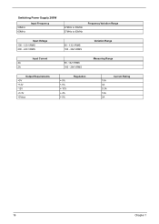
Switching Power Supply 200W 50MHz 60MHz Input Frequency 47MHz to 53MHz 57MHz to 63MHz Frequency Variation Range Input Voltage 100 - 120 VRMS 200 - 240 VRMS 90 - 132 VRMS 180 - 264 VRMS Variation Range Input Current 4A 2A 90 -132 VRMS 180 - 264 VRMS Measuring Range Output Requirements +5V +12V -12V +3.3V +5Vaux +-5% +-5% +-10% +-4% +-5% Regulation 15A 3A 0.3A 12A 3A Current Rating 16 Chapter 1
Switching Power Supply 200W 50MHz 60MHz Input Frequency 47MHz to 53MHz 57MHz to 63MHz Frequency Variation Range Input Voltage 100 - 120 VRMS 200 - 240 VRMS 90 - 132 VRMS 180 - 264 VRMS Variation Range Input Current 4A 2A 90 -132 VRMS 180 - 264 VRMS Measuring Range Output Requirements +5V +12V -12V +3.3V +5Vaux +-5% +-5% +-10% +-4% +-5% Regulation 15A 3A 0.3A 12A 3A Current Rating 16 Chapter 1
Aspire T300 Service Guide
Page 39
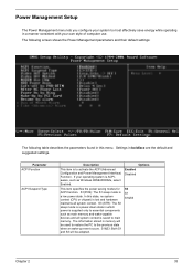
...Settings in which power is s power-down state in boldface are the default and suggested settings. S1(POS): The S1 sleep mode is lost and hardware maintains all system context is to the previous state when an wake-up event occurs. S3 (STR): The S3 sleep mode is supplied only to essential... components such as Windows 98SE/2000/Me, select Enabled. S1&S3: Both S1 and S3 will be adopted. S3 S1 S1&S3 Chapter 2 33 Enabled Disabled This item specifies the power saving modes for ACPI function. The information stored ...
...Settings in which power is s power-down state in boldface are the default and suggested settings. S1(POS): The S1 sleep mode is lost and hardware maintains all system context is to the previous state when an wake-up event occurs. S3 (STR): The S3 sleep mode is supplied only to essential... components such as Windows 98SE/2000/Me, select Enabled. S1&S3: Both S1 and S3 will be adopted. S3 S1 S1&S3 Chapter 2 33 Enabled Disabled This item specifies the power saving modes for ACPI function. The information stored ...
Aspire T300 Service Guide
Page 51
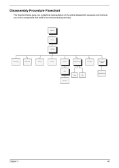
Disassembly Procedure Flowchart The flowchart below gives you a graphical representation on the entire disassembly sequence and instructs you on the components that need to be removed during servicing. Main Unit Top Cover CD ROM Power Supply Modem Card VGA Card Memory Heatsink Floppy/HDD Cage Front Bezel Daughter Board Bracket CPU Mainboard Floppy HDD Daughter Board Chapter 3 45
Disassembly Procedure Flowchart The flowchart below gives you a graphical representation on the entire disassembly sequence and instructs you on the components that need to be removed during servicing. Main Unit Top Cover CD ROM Power Supply Modem Card VGA Card Memory Heatsink Floppy/HDD Cage Front Bezel Daughter Board Bracket CPU Mainboard Floppy HDD Daughter Board Chapter 3 45
Aspire T300 Service Guide
Page 63
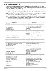
... FRU indicated in "Error Sympton List". System board 1. PS/2 keyboard 4. Diskette drive. 3. IDE hard disk drive. 57 Also check the power supply voltages if you have done so, you must run the diagnostics program tests but did receive a POST error message, use "POST Error Messages...BIOS Setup and load the default settings. 3. System board. 1. PS/2 mouse 5. Remove all adapter cards that are NOT factory- Remove all power supply voltages, switch, and jumper settings before you replace the main board. BIOS Messages I/O Parity Error CPU Clock Mismatch Real Time Clock Error CMOS ...
... FRU indicated in "Error Sympton List". System board 1. PS/2 keyboard 4. Diskette drive. 3. IDE hard disk drive. 57 Also check the power supply voltages if you have done so, you must run the diagnostics program tests but did receive a POST error message, use "POST Error Messages...BIOS Setup and load the default settings. 3. System board. 1. PS/2 mouse 5. Remove all adapter cards that are NOT factory- Remove all power supply voltages, switch, and jumper settings before you replace the main board. BIOS Messages I/O Parity Error CPU Clock Mismatch Real Time Clock Error CMOS ...
Aspire T300 Service Guide
Page 65
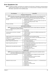
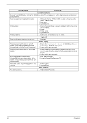
...diagnosing any system problems. Memory test failed. 1. Processor 2. See "Memory" 2. Insert the memory modules in chapter 2. 2. System works but power supply fan runs. 1. See "Undetermined Problems" System hangs after system boot. 1. system does not work . 1. Diskette drive 5. If directed ..."Undetermined Problems". Diskette drive connection/cable 4. Error Symptoms List NOTE: To diagnose a problem, first find the error symptom in power saving mode. Its reading should be +12Vdc. 3. System board. Diskette/IDE disk drives 3. Diskette/IDE drive connection/cables 2. ...
...diagnosing any system problems. Memory test failed. 1. Processor 2. See "Memory" 2. Insert the memory modules in chapter 2. 2. System works but power supply fan runs. 1. See "Undetermined Problems" System hangs after system boot. 1. system does not work . 1. Diskette drive 5. If directed ..."Undetermined Problems". Diskette drive connection/cable 4. Error Symptoms List NOTE: To diagnose a problem, first find the error symptom in power saving mode. Its reading should be +12Vdc. 3. System board. Diskette/IDE disk drives 3. Diskette/IDE drive connection/cables 2. ...
Aspire T300 Service Guide
Page 68
... the system). 1. Load default settings. 2. System Board Other Problems Any other problems. 1. Refer to the service manual for the power cable) is the same as the setting in BIOS Setup. 2. Keyboard Power Supply Pressing power switch does not turn off the system.) 1. Error Symptom Action/FRU Parallel/Serial Ports Execute "Load BIOS Default Settings...
... the system). 1. Load default settings. 2. System Board Other Problems Any other problems. 1. Refer to the service manual for the power cable) is the same as the setting in BIOS Setup. 2. Keyboard Power Supply Pressing power switch does not turn off the system.) 1. Error Symptom Action/FRU Parallel/Serial Ports Execute "Load BIOS Default Settings...
Power ST User Guide
Page 6
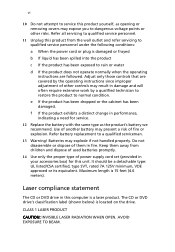
...from children and dispose of used batteries promptly. 14 Use only the proper type of fire or explosion. Batteries may present a risk of power supply cord set (provided in your accessories box) for service. 12 Replace the battery with the same type as opening or removing covers may ...instructions since improper adjustment of them away from the wall outlet and refer servicing to qualified service personnel under the following conditions: a When the power cord or plug is a laser product. Maximum length is located on the drive. Adjust only those controls that are followed. The CD ...
...from children and dispose of used batteries promptly. 14 Use only the proper type of fire or explosion. Batteries may present a risk of power supply cord set (provided in your accessories box) for service. 12 Replace the battery with the same type as opening or removing covers may ...instructions since improper adjustment of them away from the wall outlet and refer servicing to qualified service personnel under the following conditions: a When the power cord or plug is a laser product. Maximum length is located on the drive. Adjust only those controls that are followed. The CD ...


