
Power SC Service Guide
Page 32
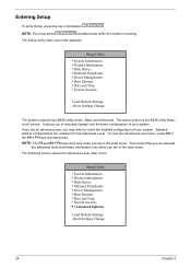
NOTE: You must press simultaneously while the system is the BIOS Utility Basic Level screen. Disk Drives ! System Information ! Onboard Peripherals ! Power Management ! The above screen is booting. This means that you can activate the advanced level and hidden information only when you ...are an advanced user, you are in the Advanced Level. Onboard Peripherals ! Power Management ! If you may want to view and change only the basic configuration of your system. The following screen shows the Advanced Level main menu: Setup Utility ! The Setup Utility main ...
NOTE: You must press simultaneously while the system is the BIOS Utility Basic Level screen. Disk Drives ! System Information ! Onboard Peripherals ! Power Management ! The above screen is booting. This means that you can activate the advanced level and hidden information only when you ...are an advanced user, you are in the Advanced Level. Onboard Peripherals ! Power Management ! If you may want to view and change only the basic configuration of your system. The following screen shows the Advanced Level main menu: Setup Utility ! The Setup Utility main ...
Power SC Service Guide
Page 36
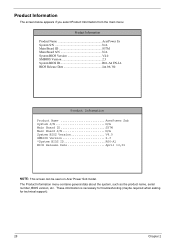
...). 28 Chapter 2 The Product Information menu contains general data about the system, such as the product name, serial number, BIOS version, etc. Product Information The screen below appears if you select Product Information from the main menu: Product Information Product Name AcerPower Sx System S/N N/A Main Board ID S57M Main Board S/N N/A System... S/N N/A Main Board ID S57M Main Board S/N N/A System BIOS Version V4.0 SMBIOS Version 2.3 *System BIOS ID R06-A1 BIOS Release Date April 16,01 NOTE: This screen can be seen on Acer Power Sxb model.
...). 28 Chapter 2 The Product Information menu contains general data about the system, such as the product name, serial number, BIOS version, etc. Product Information The screen below appears if you select Product Information from the main menu: Product Information Product Name AcerPower Sx System S/N N/A Main Board ID S57M Main Board S/N N/A System... S/N N/A Main Board ID S57M Main Board S/N N/A System BIOS Version V4.0 SMBIOS Version 2.3 *System BIOS ID R06-A1 BIOS Release Date April 16,01 NOTE: This screen can be seen on Acer Power Sxb model.
Power SC Service Guide
Page 42
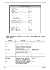
...] Onboard Audio Chip Enabled] Game Port Address 201] MIDI Port Address 330] MIDI Port IRQ 5] Onboard Modem Chip Disabled] Onboard Ethernet Chip Enabled] NOTE: This screen can be seen on Acer Power Sxb model.
...] Onboard Audio Chip Enabled] Game Port Address 201] MIDI Port Address 330] MIDI Port IRQ 5] Onboard Modem Chip Disabled] Onboard Ethernet Chip Enabled] NOTE: This screen can be seen on Acer Power Sxb model.
Power SC Service Guide
Page 44
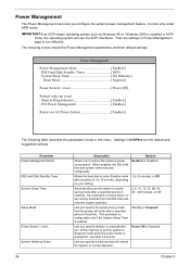
...installed in boldface are the default and suggested settings. Then the settings in this menu. The following screen shows the Power Management parameters and their default settings: Power Management Power Management Mode Enabled ] IDE Hard Disk Standby Timer OFF] System Sleep Timer 30] Minute(s) Sleep ... normal operation. Settings in ACPI mode, the operating system will use the ACPI interfaces. Lets you to reduce the system's power consumption. Lets you configure the system power-management feature. Options Enabled or Disabled 1 to 15 minutes, or Off 2, 5, 10, 15, 20, 30, 40...
...installed in boldface are the default and suggested settings. Then the settings in this menu. The following screen shows the Power Management parameters and their default settings: Power Management Power Management Mode Enabled ] IDE Hard Disk Standby Timer OFF] System Sleep Timer 30] Minute(s) Sleep ... normal operation. Settings in ACPI mode, the operating system will use the ACPI interfaces. Lets you to reduce the system's power consumption. Lets you configure the system power-management feature. Options Enabled or Disabled 1 to 15 minutes, or Off 2, 5, 10, 15, 20, 30, 40...
Power SC Service Guide
Page 72
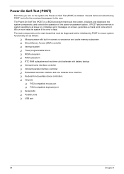
...ports ! I/O ports ! USB port 64 Chapter 4 RTC RAM subsystem and real time clock/calendar with built-in system operations at power-on, it displays error messages on screen, generates a check point code at port 80h or even halts the system if the error is for the most part transparent to... controllers ! The main components on the main board that boots the system, initializes and diagnoses the system components, and controls the operation of the power-on Self Test (POST) is a BIOS procedure that must be diagnosed and/or initialized by POST to the user. Direct Memory Access (DMA)...
...ports ! I/O ports ! USB port 64 Chapter 4 RTC RAM subsystem and real time clock/calendar with built-in system operations at power-on, it displays error messages on screen, generates a check point code at port 80h or even halts the system if the error is for the most part transparent to... controllers ! The main components on the main board that boots the system, initializes and diagnoses the system components, and controls the operation of the power-on Self Test (POST) is a BIOS procedure that must be diagnosed and/or initialized by POST to the user. Direct Memory Access (DMA)...
Power SC Service Guide
Page 75
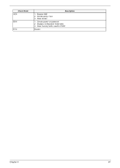
Clear memory buffer used for POST Bootint Chapter 4 67 Check Point ACH B0H B1H Description 1. Clear screen 1. Enables NMI 2. Checks power-on password 2. Displays configuration mode table 3. Checks parity, if set 3.
Clear memory buffer used for POST Bootint Chapter 4 67 Check Point ACH B0H B1H Description 1. Clear screen 1. Enables NMI 2. Checks power-on password 2. Displays configuration mode table 3. Checks parity, if set 3.
Power SC Service Guide
Page 80
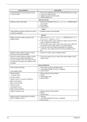
... , reinsert the modem card to system board is readable). 3. Monitor signal connection/cable. 2. System board 1. Load default settings (if screen is connected properly. 4. Incorrect colors No high intensity Missing, broken, or incorrect characters Blank monitor(dark) Blank monitor(bright) Distorted image ...Unreadable monitor Other monitor problems Display changing colors. Real-Time Clock 1. Load default settings (if screen is used , ensure the modem ring-in BIOS Setup or Power Management is inaccurate. Video adapter card 4. voice from modem cannot be produced, but no sound ...
... , reinsert the modem card to system board is readable). 3. Monitor signal connection/cable. 2. System board 1. Load default settings (if screen is connected properly. 4. Incorrect colors No high intensity Missing, broken, or incorrect characters Blank monitor(dark) Blank monitor(bright) Distorted image ...Unreadable monitor Other monitor problems Display changing colors. Real-Time Clock 1. Load default settings (if screen is used , ensure the modem ring-in BIOS Setup or Power Management is inaccurate. Video adapter card 4. voice from modem cannot be produced, but no sound ...
Power Sc User's Guide
Page 14
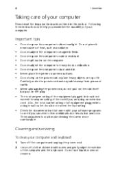
... cables away from personal traffic. The total ampere rating of the equipment plugged in should not exceed the fuse rating. When unplugging the power cord, do not pull on the cord itself but pull on uneven surfaces. Important tips Do not expose the computer to dust and ... computer and the keyboard. Do not spill water on top of it near sources of heat, such as a radiator. These adjustments could make viewing the screen more comfortable. • • • Cleaning and servicing To clean your software programs to heavy shock or vibration. 4 1 Overview Taking care of...
... cables away from personal traffic. The total ampere rating of the equipment plugged in should not exceed the fuse rating. When unplugging the power cord, do not pull on the cord itself but pull on uneven surfaces. Important tips Do not expose the computer to dust and ... computer and the keyboard. Do not spill water on top of it near sources of heat, such as a radiator. These adjustments could make viewing the screen more comfortable. • • • Cleaning and servicing To clean your software programs to heavy shock or vibration. 4 1 Overview Taking care of...


