

Power SC Service Guide
Page 65
Chapter 3 57 Disconnect the disk drive cables and the power cable. Removing a 3.5-inch Drive Follow these steps to install a 3.5-inch diskette drive or a hard disk drive: 1.
Chapter 3 57 Disconnect the disk drive cables and the power cable. Removing a 3.5-inch Drive Follow these steps to install a 3.5-inch diskette drive or a hard disk drive: 1.

Power SC Service Guide
Page 67
Remove the screws on the sides and gently pull out the diskette drive or CD-ROM to remove it from the housing. Chapter 3 59 Removing a 5.25-inch Drive To remove a 5.25-inch diskette drive or a CD-ROM drive: 1. Disconnect the diskette drive cable and the power cable. 2.
Remove the screws on the sides and gently pull out the diskette drive or CD-ROM to remove it from the housing. Chapter 3 59 Removing a 5.25-inch Drive To remove a 5.25-inch diskette drive or a CD-ROM drive: 1. Disconnect the diskette drive cable and the power cable. 2.
Power SC Service Guide
Page 76
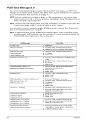
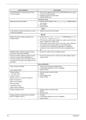
... column. Enter BIOS Setup to a check procedure, replace the FRU indicated in BIOS Setup is set in the check procedure. Diskette drive cable/connection. 2. installed, then reboot the system. 1. BIOS Messages I/O Parity Error CPU Clock Mismatch Real Time Clock Error CMOS Battery Bad ... system configuration set correctly. 1. Enter BIOS Setup and load the default settings. 3. Enter BIOS Setup and load the default settings. 2. Remove all power supply voltages, switch, and jumper settings before you have done so, you did receive a POST error message, use "POST Error Messages List" to...
... column. Enter BIOS Setup to a check procedure, replace the FRU indicated in BIOS Setup is set in the check procedure. Diskette drive cable/connection. 2. installed, then reboot the system. 1. BIOS Messages I/O Parity Error CPU Clock Mismatch Real Time Clock Error CMOS Battery Bad ... system configuration set correctly. 1. Enter BIOS Setup and load the default settings. 3. Enter BIOS Setup and load the default settings. 2. Remove all power supply voltages, switch, and jumper settings before you have done so, you did receive a POST error message, use "POST Error Messages List" to...
Power SC Service Guide
Page 77
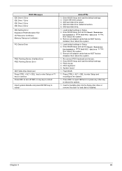
IDE hard disk drive power. 4. Enter BIOS Setup and set the Reset Resource Assignments of the PnP/PCI Options to Yes, then reboot the system. 3. Remove all adapter cards that ... to Yes, then reboot the system. 3. Load default settings in Setup. 2. Press CTRL + ALT + DEL to reboot Action/FRU 1. Chapter 4 69 IDE hard disk drive cable/connection. 5. Remove all adapter cards that are NOT factoryinstalled, then reboot the system. 1. Check IDE drive jumper. 3. Re-connect PS/2 keyboard and mouse. 2. BIOS Messages...
IDE hard disk drive power. 4. Enter BIOS Setup and set the Reset Resource Assignments of the PnP/PCI Options to Yes, then reboot the system. 3. Remove all adapter cards that ... to Yes, then reboot the system. 3. Load default settings in Setup. 2. Press CTRL + ALT + DEL to reboot Action/FRU 1. Chapter 4 69 IDE hard disk drive cable/connection. 5. Remove all adapter cards that are NOT factoryinstalled, then reboot the system. 1. Check IDE drive jumper. 3. Re-connect PS/2 keyboard and mouse. 2. BIOS Messages...
Power SC Service Guide
Page 78
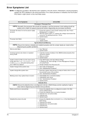
...power 3. System board. Processor test failed. 1. System board Incorrect memory size shown or repeated during POST. 1. In Windows 98, check settings in the Disk Drives of BIOS Setup. 2. See "Undetermined Problems" System hangs after system boot. 1. system does not work . 1. Diskette drive connection/cable... indicated, the first Action/ FRU listed in BIOS has elapsed. 1. Ensure the diskette drive is configured correctly in Power Management Property of the problem. 2. Error Symptom Action/FRU Processor / Processor Fan NOTE: Normally, the processor fan ...
...power 3. System board. Processor test failed. 1. System board Incorrect memory size shown or repeated during POST. 1. In Windows 98, check settings in the Disk Drives of BIOS Setup. 2. See "Undetermined Problems" System hangs after system boot. 1. system does not work . 1. Diskette drive connection/cable... indicated, the first Action/ FRU listed in BIOS has elapsed. 1. Ensure the diskette drive is configured correctly in Power Management Property of the problem. 2. Error Symptom Action/FRU Processor / Processor Fan NOTE: Normally, the processor fan ...
Power SC Service Guide
Page 79
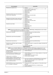
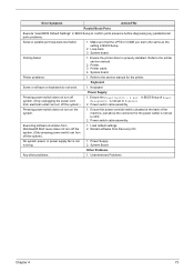
.../DVD-ROM drive LED flashes for more than 30 seconds before LED shutting off. CD/DVD-ROM is damaged. Disconnect all cables from CD/DVD-ROM drive except power cable, then press eject button to try to light, but works normally. 1. Enter BIOS Setup and Load default settings. 2. ...System board. Hard drive LED cable. Software asks to Write protect in BIOS Setup, cable/jumper are set to reinstall disc. Diskette 2. Enter BIOS...
.../DVD-ROM drive LED flashes for more than 30 seconds before LED shutting off. CD/DVD-ROM is damaged. Disconnect all cables from CD/DVD-ROM drive except power cable, then press eject button to try to light, but works normally. 1. Enter BIOS Setup and Load default settings. 2. ...System board. Hard drive LED cable. Software asks to Write protect in BIOS Setup, cable/jumper are set to reinstall disc. Diskette 2. Enter BIOS...
Power SC Service Guide
Page 80
... Unreadable monitor Other monitor problems Display changing colors. Modem 1. Load default settings (if screen is connected properly. 4. Monitor signal connection/cable 2. Audio software program invokes but no sound output. Speaker power/connection/cable. 4. If PCI modem card is set correctly. 2. System board 1. System board 72 Chapter 4 Turn up system from suspend mode. Speaker...
... Unreadable monitor Other monitor problems Display changing colors. Modem 1. Load default settings (if screen is connected properly. 4. Monitor signal connection/cable 2. Audio software program invokes but no sound output. Speaker power/connection/cable. 4. If PCI modem card is set correctly. 2. System board 1. System board 72 Chapter 4 Turn up system from suspend mode. Speaker...
Power SC Service Guide
Page 81
System board. Printing failed. 1. Ensure the Power Switch < 4 sec. Ensure the power override switch (situated at the back of Power Management is not set to the service manual for the power cable) is the same as the setting in BIOS Setup to ...from electrical outlet can turn off the system.) 1. Power Supply 2. Keyboard Some or all keys on the system. 1. Power switch cable assembly. No system power, or power supply fan is properly installed. Printer problems. 1. Power switch cable assembly Pressing power switch does not turn off the system). 1. Refer...
System board. Printing failed. 1. Ensure the Power Switch < 4 sec. Ensure the power override switch (situated at the back of Power Management is not set to the service manual for the power cable) is the same as the setting in BIOS Setup to ...from electrical outlet can turn off the system.) 1. Power Supply 2. Keyboard Some or all keys on the system. 1. Power switch cable assembly. No system power, or power supply fan is properly installed. Printer problems. 1. Power switch cable assembly Pressing power switch does not turn off the system). 1. Refer...

Power SC Service Guide
Page 84
...in "or "Error Symptoms List" on page 70. Non-Acer devices ! Diskette drive ! Check all cables and connectors for proper installation. 9. System board 11. Undetermined Problems If an error message is listed in setup. 5. Check the power supply voltages. Perform the following , one , until you...check: 1. Repeat steps 2 through 5 until you still cannot solve the problem, continue with the following steps: 2. CD/DVD-ROM drive ! Power off the system unit. 3. Check all device jumper positions. 8. If the voltages are correct, remove or disconnect the following checks, one by...
...in "or "Error Symptoms List" on page 70. Non-Acer devices ! Diskette drive ! Check all cables and connectors for proper installation. 9. System board 11. Undetermined Problems If an error message is listed in setup. 5. Check the power supply voltages. Perform the following , one , until you...check: 1. Repeat steps 2 through 5 until you still cannot solve the problem, continue with the following steps: 2. CD/DVD-ROM drive ! Power off the system unit. 3. Check all device jumper positions. 8. If the voltages are correct, remove or disconnect the following checks, one by...

Power SC Service Guide
Page 98
... CHA Description KNOB PWR CHA HIPS 002 H61 Part No. 42.92219.011 NS Power switch knob spring SPRING POWER KNOB 34.02708.001 SUS IDCMT/FU 17 Key lock KEY LOCK SUS430 IDK 34....00115.001 15 RTG Bracket port spring SPRING PLT (A) PBSPS T- 34.93409.001 .15 H40 7 LED cable catch HOLDER WIRI ...PLT SLOT (B) CU H40 40.92201.341 47.91012.001 31. 93401.001 Keyboard NS Switch/LED cable kit ASSY SWITCH/LED CABLE 6K.92201.001 PACK H61 NS Keyboard, 104 key US, 52VL KB 104 Key US/ 6511-V41/L...
... CHA Description KNOB PWR CHA HIPS 002 H61 Part No. 42.92219.011 NS Power switch knob spring SPRING POWER KNOB 34.02708.001 SUS IDCMT/FU 17 Key lock KEY LOCK SUS430 IDK 34....00115.001 15 RTG Bracket port spring SPRING PLT (A) PBSPS T- 34.93409.001 .15 H40 7 LED cable catch HOLDER WIRI ...PLT SLOT (B) CU H40 40.92201.341 47.91012.001 31. 93401.001 Keyboard NS Switch/LED cable kit ASSY SWITCH/LED CABLE 6K.92201.001 PACK H61 NS Keyboard, 104 key US, 52VL KB 104 Key US/ 6511-V41/L...
Power Sc User's Guide
Page 9
... Arranging a comfortable work area Adjusting your chair Positioning your PC Positioning your monitor Positioning your keyboard Positioning your mouse Connecting peripherals Mouse USB Keyboard Monitor Power cable Connecting options Printer Network Modem Multimedia devices USB devices 21 23 23 23 23 24 24 25 25 26 27 28 29 29 30 31...
... Arranging a comfortable work area Adjusting your chair Positioning your PC Positioning your monitor Positioning your keyboard Positioning your mouse Connecting peripherals Mouse USB Keyboard Monitor Power cable Connecting options Printer Network Modem Multimedia devices USB devices 21 23 23 23 23 24 24 25 25 26 27 28 29 29 30 31...
Power Sc User's Guide
Page 13
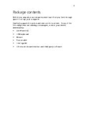
Carefully unpack the carton and remove the contents. If any of the following items are missing or damaged, contact your computer. 3 Package contents Before you unpack your computer, make sure that you have enough space to set up your dealer immediately AcerPower SC USB keyboard Mouse Power cable User's guide Other user documentation and third-party software
Carefully unpack the carton and remove the contents. If any of the following items are missing or damaged, contact your computer. 3 Package contents Before you unpack your computer, make sure that you have enough space to set up your dealer immediately AcerPower SC USB keyboard Mouse Power cable User's guide Other user documentation and third-party software
Power Sc User's Guide
Page 14
Do not subject the computer to heavy shock or vibration. Do not subject the computer to magnetic fields. Carefully route the power cord and any cables away from personal traffic. Check the documentation that came with water and gently wipe the exterior of the computer and the keyboard. 4 ...1 Overview Taking care of your computer and keyboard 1 2 Turn off the computer and unplug the power cord. Following these instructions will help ...
Do not subject the computer to heavy shock or vibration. Do not subject the computer to magnetic fields. Carefully route the power cord and any cables away from personal traffic. Check the documentation that came with water and gently wipe the exterior of the computer and the keyboard. 4 ...1 Overview Taking care of your computer and keyboard 1 2 Turn off the computer and unplug the power cord. Following these instructions will help ...

Power Sc User's Guide
Page 35
Connecting the PS/2 mouse Connecting the USB mouse Mouse Plug the mouse cable into the PS/2 mouse port or USB port located on the rear panel of your computer is easy. For the most part, you only have four things to connect: the mouse, the USB keyboard, the monitor and the power cable. 25 Connecting peripherals Setting up your computer.
Connecting the PS/2 mouse Connecting the USB mouse Mouse Plug the mouse cable into the PS/2 mouse port or USB port located on the rear panel of your computer is easy. For the most part, you only have four things to connect: the mouse, the USB keyboard, the monitor and the power cable. 25 Connecting peripherals Setting up your computer.

Power Sc User's Guide
Page 38
28 3 Setting up your computer Power cable Caution: Before you proceed, check the voltage range in your computer. Plug the power cable into a power outlet. Then plug the other end of the power cable into the power cable socket located on the rear panel of your area. Make sure that it matches your computer's voltage setting (see the voltage setting switch located on the rear panel of your area's voltage range. If they don't match, change your computer's voltage setting according to your computer).
28 3 Setting up your computer Power cable Caution: Before you proceed, check the voltage range in your computer. Plug the power cable into a power outlet. Then plug the other end of the power cable into the power cable socket located on the rear panel of your area. Make sure that it matches your computer's voltage setting (see the voltage setting switch located on the rear panel of your area's voltage range. If they don't match, change your computer's voltage setting according to your computer).

Power Sc User's Guide
Page 44
To turn on your computer: 1 2 Turn on all peripherals connected to work. Locate and turn on the main power switch on the rear panel of your computer such as the monitor, printer, fax, speakers, etc. 34 3 Setting up your computer Turning on your computer After connecting the necessary peripherals and plugging in the power cable, you are now ready to turn the computer on and get to your computer.
To turn on your computer: 1 2 Turn on all peripherals connected to work. Locate and turn on the main power switch on the rear panel of your computer such as the monitor, printer, fax, speakers, etc. 34 3 Setting up your computer Turning on your computer After connecting the necessary peripherals and plugging in the power cable, you are now ready to turn the computer on and get to your computer.

Power Sc User's Guide
Page 45
Make sure that it is properly plugged into an electrical outlet. If you are using a power strip or an AVR (Auto-Voltage Regulator), make sure that the power cable is now ready for use. When the computer finishes booting, it is plugged in and turned on. Important! 35 3 On the front panel of your computer, press the power button.
Make sure that it is properly plugged into an electrical outlet. If you are using a power strip or an AVR (Auto-Voltage Regulator), make sure that the power cable is now ready for use. When the computer finishes booting, it is plugged in and turned on. Important! 35 3 On the front panel of your computer, press the power button.
Power Sc User's Guide
Page 49
... instructions on page 41. Follow the ESD precautions described above before you install a system component: 1 2 Do not remove a component from the power outlets. Not turning off your computer and all cables from its protective packaging until you are a qualified service technician. If a wrist strap is not available, maintain contact with preinstallation and...
... instructions on page 41. Follow the ESD precautions described above before you install a system component: 1 2 Do not remove a component from the power outlets. Not turning off your computer and all cables from its protective packaging until you are a qualified service technician. If a wrist strap is not available, maintain contact with preinstallation and...

Power Sc User's Guide
Page 51
You need them when replacing the housing cover. See the following section for instructions. Place the system unit on page 39. You will need to open your computer before you have turned off the system power and unplug all peripherals connected to it. Read the "Preinstallation instructions" on a flat, steady surface. Set the screws aside. Removing the cover 1 2 3 Turn off your computer and all cables. Remove the four screws from the rear panel. 41 Opening your computer Caution: Before you proceed, make sure that you can install additional components.
You need them when replacing the housing cover. See the following section for instructions. Place the system unit on page 39. You will need to open your computer before you have turned off the system power and unplug all peripherals connected to it. Read the "Preinstallation instructions" on a flat, steady surface. Set the screws aside. Removing the cover 1 2 3 Turn off your computer and all cables. Remove the four screws from the rear panel. 41 Opening your computer Caution: Before you proceed, make sure that you can install additional components.

Power Sc User's Guide
Page 66
56 c 4 Upgrading your computer Connect the disk drive cables and power cables. Note: Make sure that the other ends of the floppy disk drive cables are connected to their corresponding connectors on the system board. 7 Reinstall the housing cover as instructed on page 43.
56 c 4 Upgrading your computer Connect the disk drive cables and power cables. Note: Make sure that the other ends of the floppy disk drive cables are connected to their corresponding connectors on the system board. 7 Reinstall the housing cover as instructed on page 43.


