
Aspire T690 User's Guide EN
Page 6
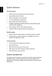
2 System tour English System features Performance • Intel® mainstream high-performance processor • Expandable system memory • Power management functionality • 3.5" inch floppy drive (optional) • Multimedia card reader (optional) • CD-ROM, DVD-ROM, CD-RW (52X/24X), DVD/CD-RW combo ...
2 System tour English System features Performance • Intel® mainstream high-performance processor • Expandable system memory • Power management functionality • 3.5" inch floppy drive (optional) • Multimedia card reader (optional) • CD-ROM, DVD-ROM, CD-RW (52X/24X), DVD/CD-RW combo ...
Aspire T690 User's Guide EN
Page 10
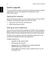
... the panel back and off the computer and unplug the power cord from a CD-ROM drive to high-capacity HDD - Before you choose new components, please ask your authorized Acer dealer whether the part will operate within your new components. Expand high-level memory - Upgrade to CD-RW, DVD-ROM, DVD/CD-RW...
... the panel back and off the computer and unplug the power cord from a CD-ROM drive to high-capacity HDD - Before you choose new components, please ask your authorized Acer dealer whether the part will operate within your new components. Expand high-level memory - Upgrade to CD-RW, DVD-ROM, DVD/CD-RW...
Aspire T670 and Power Fe Service Guide
Page 5
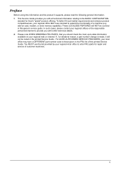
... with all technical information relating to the BASIC CONFIGURATION decided for Acer's "global" product offering. In such cases, please contact your regional web or channel. For ACER-AUTHORIZED SERVICE PROVIDERS, your Acer office may have decided to order FRU parts for whatever reason,... DIFFERENT part number code to -date information available on card, modem, or extra memory capability). To better fit local market requirements and enhance product competitiveness, your regional Acer office to extend the functionality of this generic service guide. These LOCALIZED FEATURES will...
... with all technical information relating to the BASIC CONFIGURATION decided for Acer's "global" product offering. In such cases, please contact your regional web or channel. For ACER-AUTHORIZED SERVICE PROVIDERS, your Acer office may have decided to order FRU parts for whatever reason,... DIFFERENT part number code to -date information available on card, modem, or extra memory capability). To better fit local market requirements and enhance product competitiveness, your regional Acer office to extend the functionality of this generic service guide. These LOCALIZED FEATURES will...
Aspire T670 and Power Fe Service Guide
Page 6
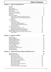
... Panel 11 AcerPower FE Front Panel 12 Rear Panel 13 System Peripherals 14 Mouse (PS/2 or USB, manufacturing option 14 Keyboard (PS/2 or USB, manufacturing option 14 Speakers 15 Acer eRecovery 16 Create ...CD 17 Change Password 17 Acer disc-to-disc recovery 18 Restore without a Recovery CD 18 Multilingual operating system installation 18 Hardware Specifications and Configurations 19 Power Management Function (ACPI support function... TV Tuner Card 52 Removing the Heatsink and CPU 52 Removing the Memory 53 Removing the Cables 53 Removing the Cables from Devices 54 Removing the HDD ...
... Panel 11 AcerPower FE Front Panel 12 Rear Panel 13 System Peripherals 14 Mouse (PS/2 or USB, manufacturing option 14 Keyboard (PS/2 or USB, manufacturing option 14 Speakers 15 Acer eRecovery 16 Create ...CD 17 Change Password 17 Acer disc-to-disc recovery 18 Restore without a Recovery CD 18 Multilingual operating system installation 18 Hardware Specifications and Configurations 19 Power Management Function (ACPI support function... TV Tuner Card 52 Removing the Heatsink and CPU 52 Removing the Memory 53 Removing the Cables 53 Removing the Cables from Devices 54 Removing the HDD ...
Aspire T670 and Power Fe Service Guide
Page 8
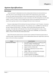
no pins on board audio function. This model with a socket protector that there are still contact surfaces - AcerPower FE will be the product name for more details address toward each chipset that be used in terms of damaged CPUs due to bent or broken .... Chapter 1 System Specifications Overview All the new Socket-T motherboards come with one PCI-Express x16 slot, three PCI slots (support PCI 2.2 spec.), 2 Dual Channel DDR 1 memory slots (support up to 2GB), one P-ATA devices (HDD/ODD), two S-ATA devices (HDDs), on board 10/100 LAN, and on the bottom of...
no pins on board audio function. This model with a socket protector that there are still contact surfaces - AcerPower FE will be the product name for more details address toward each chipset that be used in terms of damaged CPUs due to bent or broken .... Chapter 1 System Specifications Overview All the new Socket-T motherboards come with one PCI-Express x16 slot, three PCI slots (support PCI 2.2 spec.), 2 Dual Channel DDR 1 memory slots (support up to 2GB), one P-ATA devices (HDD/ODD), two S-ATA devices (HDDs), on board 10/100 LAN, and on the bottom of...

Aspire T670 and Power Fe Service Guide
Page 10
... D 2.53GHz ~ 3.2GHz L2 Cache varies with CPU from 1MB to 2MB Chipset T Northbridge: Intel 915GL T Southbridge: ICH6 Memory T Socket Type : DDR , 2.5 Voltage T Socket Quantity : 2 T Capacity support : 128MB ~ 2GB T Support Memory Speed : 400/333 MHz Graphic Solution T Intel Grantsdale-GL on-die graphic solution T DVMT(Dynamic Video... Memory Technology ) technology support Slots T T 1 PCI Express x16 slot 3 PCI 2.2 5V slots FDD T T One 1.44MB 3.5" device Allow connection of 2 FDD devices IDE ...
... D 2.53GHz ~ 3.2GHz L2 Cache varies with CPU from 1MB to 2MB Chipset T Northbridge: Intel 915GL T Southbridge: ICH6 Memory T Socket Type : DDR , 2.5 Voltage T Socket Quantity : 2 T Capacity support : 128MB ~ 2GB T Support Memory Speed : 400/333 MHz Graphic Solution T Intel Grantsdale-GL on-die graphic solution T DVMT(Dynamic Video... Memory Technology ) technology support Slots T T 1 PCI Express x16 slot 3 PCI 2.2 5V slots FDD T T One 1.44MB 3.5" device Allow connection of 2 FDD devices IDE ...

Aspire T670 and Power Fe Service Guide
Page 12
... S1/S3 Amber Steady S4/S5 Off HDD state LED IDE active Red Blinking IDE idle Off System LED definition (for P451 AcerPower series bezel) Power State LED S0 Blue Steady S1/S3 Blue Blinking S4/S5 Off On-Board Connector T Rear I/O Connectors T 1 PS/2 Keyboard Port, 1 PS/2 Mouse Port ...T 4 USB Ports T 1 Line-in/Line-out/Mic-in port T On-Board Connectos T 1 CPU Socket T 2 Memory Slot T 1 PCI Express x16 Slot T 3 PCI Slots T 1 FDD Slot T 1 PATA IDE Slots Chapter 1 5 AcerPower series bezel) Power state LED S0 Blue Steady S1/S3 Off S4/S5 Off ODD, HDD, LAN Active Blue System...
... S1/S3 Amber Steady S4/S5 Off HDD state LED IDE active Red Blinking IDE idle Off System LED definition (for P451 AcerPower series bezel) Power State LED S0 Blue Steady S1/S3 Blue Blinking S4/S5 Off On-Board Connector T Rear I/O Connectors T 1 PS/2 Keyboard Port, 1 PS/2 Mouse Port ...T 4 USB Ports T 1 Line-in/Line-out/Mic-in port T On-Board Connectos T 1 CPU Socket T 2 Memory Slot T 1 PCI Express x16 Slot T 3 PCI Slots T 1 FDD Slot T 1 PATA IDE Slots Chapter 1 5 AcerPower series bezel) Power state LED S0 Blue Steady S1/S3 Off S4/S5 Off ODD, HDD, LAN Active Blue System...

Aspire T670 and Power Fe Service Guide
Page 14
Block Diagram PCI-ECLK (100MHz) 1 PCI Express x 4 Port 3 PCI PCI Express Bus PCI Bus RTL 8100C RJ45 LGA775 Processor CPUCLK+/-(200/133MHz) Host Interface DDR400/333MHz DIMM Intel 915GL GMCH Dual Channel Memory GMCHCLK (133/200MHz) 66MHz 33MHz 14.318MHz 48MHz BIOS Intel ICH6 2 Serial ATA ATA33/66/100 IDE Channels Floppy IT 8712 LPT Port COM Port CODEC 8 USB Ports 24MHz 33MHz PS/2 KB/Mouse PCICLK (33MHz) Center/Subwoofer Speaker Out Surround Speaker Out Side Speaker Out MIC Line-Out Line-In Chapter 1 7
Block Diagram PCI-ECLK (100MHz) 1 PCI Express x 4 Port 3 PCI PCI Express Bus PCI Bus RTL 8100C RJ45 LGA775 Processor CPUCLK+/-(200/133MHz) Host Interface DDR400/333MHz DIMM Intel 915GL GMCH Dual Channel Memory GMCHCLK (133/200MHz) 66MHz 33MHz 14.318MHz 48MHz BIOS Intel ICH6 2 Serial ATA ATA33/66/100 IDE Channels Floppy IT 8712 LPT Port COM Port CODEC 8 USB Ports 24MHz 33MHz PS/2 KB/Mouse PCICLK (33MHz) Center/Subwoofer Speaker Out Surround Speaker Out Side Speaker Out MIC Line-Out Line-In Chapter 1 7

Aspire T670 and Power Fe Service Guide
Page 25
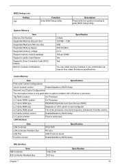
Hardware Specifications and Configurations System Board Major Chip Item System Core Logic Super I/O Controller LAN Controller Memory Controller E-IDE Controller SATA Controller RJ45 Controller Audio Controller VGA Controller PS/2 Keyboard/Mouse Controller USB Controller Specification Northbridge : Intel 915GL Southbridge : Intel ICH6 IT8712 ...
Hardware Specifications and Configurations System Board Major Chip Item System Core Logic Super I/O Controller LAN Controller Memory Controller E-IDE Controller SATA Controller RJ45 Controller Audio Controller VGA Controller PS/2 Keyboard/Mouse Controller USB Controller Specification Northbridge : Intel 915GL Southbridge : Intel ICH6 IT8712 ...
Aspire T670 and Power Fe Service Guide
Page 26
...2GB 400/333 MHz 2.5 V 184-pin DIMM Yes Yes Specification You can install memory modules in any combination as long as they match the above specifications. Cache Memory Item Specification First-Level Cache Configurations Cache function control Enable/Disable by BIOS Setup ...IDE Controller Resident Bus Intel ICH6 PCI bus Specification Chapter 1 19 System Memory Item Memory Slot Number Supported Memory Size per Slot Supported Maximum Memory Size Supported Memory Speed Supported memory voltage Support memory module package Support to parity check feature Support to enter BIOS Setup ...
...2GB 400/333 MHz 2.5 V 184-pin DIMM Yes Yes Specification You can install memory modules in any combination as long as they match the above specifications. Cache Memory Item Specification First-Level Cache Configurations Cache function control Enable/Disable by BIOS Setup ...IDE Controller Resident Bus Intel ICH6 PCI bus Specification Chapter 1 19 System Memory Item Memory Slot Number Supported Memory Size per Slot Supported Maximum Memory Size Supported Memory Speed Supported memory voltage Support memory module package Support to parity check feature Support to enter BIOS Setup ...

Aspire T670 and Power Fe Service Guide
Page 28
... / Wake-up Event Item Power On/ Wake-Up Event Description T Power Button: S1/S3/S4/S5 T PS/2 Keyboard: S1/S3/S4/S5 T RTC: S1/S5 T LAN: S1/S3/S5 Memory Address Map Address 0000000 - 009FFFF 00A0000-00BFFFF 00C0000-00CFFFF 00D0000-00D3FFF 00D4000-00D7FFF 00D8000-00DBFFF 00DC000-00DFFFF 00E0000-... Expansion ROM 16 KB I/O Expansion ROM 16 KB I/O Expansion ROM 32 KB for SCSI BIOS 32 KB 64 KB BIOS System Memory 384 KB I/O Card Memory System Memory Function Onboard DRAM Reserved for Graphics Display Buffer Non-Cacheable Reserved for ROM on I/O Adapters Reserved for ROM on I/O Adapters Reserved ...
... / Wake-up Event Item Power On/ Wake-Up Event Description T Power Button: S1/S3/S4/S5 T PS/2 Keyboard: S1/S3/S4/S5 T RTC: S1/S5 T LAN: S1/S3/S5 Memory Address Map Address 0000000 - 009FFFF 00A0000-00BFFFF 00C0000-00CFFFF 00D0000-00D3FFF 00D4000-00D7FFF 00D8000-00DBFFF 00DC000-00DFFFF 00E0000-... Expansion ROM 16 KB I/O Expansion ROM 16 KB I/O Expansion ROM 32 KB for SCSI BIOS 32 KB 64 KB BIOS System Memory 384 KB I/O Card Memory System Memory Function Onboard DRAM Reserved for Graphics Display Buffer Non-Cacheable Reserved for ROM on I/O Adapters Reserved for ROM on I/O Adapters Reserved ...
Aspire T670 and Power Fe Service Guide
Page 32
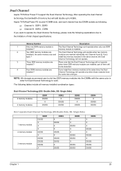
...the limitation of them will operate when two memory installed ( the same memory size and modules are If you install four memory modules at the same time, the Dual installed ? Aspire T670/AcerPower FE inculde 4 DIMM slots, and each channel ... X DS/SS DDR4 X DS/SS DS/SS Don't operate Dual Channel Technology (DS:Double Side, SS: Single Side) 1 memory module 2 memory module 3 memory module DDR1 DS/SS X X X DS/SS X DS/SS DS/SS DS/SS X DDR2 X DS/SS X X DS...DS/SS X DS/SS X DS/SS DS/SS DS/SS Chapter 1 25 Dual Channel Aspire T670/Acer Power F3 support the Dual Channel Technology.
...the limitation of them will operate when two memory installed ( the same memory size and modules are If you install four memory modules at the same time, the Dual installed ? Aspire T670/AcerPower FE inculde 4 DIMM slots, and each channel ... X DS/SS DDR4 X DS/SS DS/SS Don't operate Dual Channel Technology (DS:Double Side, SS: Single Side) 1 memory module 2 memory module 3 memory module DDR1 DS/SS X X X DS/SS X DS/SS DS/SS DS/SS X DDR2 X DS/SS X X DS...DS/SS X DS/SS X DS/SS DS/SS DS/SS Chapter 1 25 Dual Channel Aspire T670/Acer Power F3 support the Dual Channel Technology.

Aspire T670 and Power Fe Service Guide
Page 37
Holt On Base Memory Extended Memory Total Memory [All, But Keyboard] 640K 127M 128M 1 to 31 (or maximum allowed in the month) 1999 to 2098 KLJI: Move Enter: Select +/-/PU/PD: Value F5: ...
Holt On Base Memory Extended Memory Total Memory [All, But Keyboard] 640K 127M 128M 1 to 31 (or maximum allowed in the month) 1999 to 2098 KLJI: Move Enter: Select +/-/PU/PD: Value F5: ...
Aspire T670 and Power Fe Service Guide
Page 38
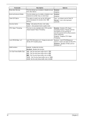
...2.88Mbyte capacity This parameter enables you to control the system stops in the computer. Parameter IDE Primary/Secondary Master, Slave Drive A Halt On Memory Description Allows you to configure the hard disk drive connected to the master port of the BIOS. it will stop for all other errors (...But Diskette : The system boot will skip the automatic detection step and allow for faster system start up Manual : User can use one of Power On Self Test errors (POST) No Errors : The system boot will stop for automatic device detection. The category is display-only which is always...
...2.88Mbyte capacity This parameter enables you to control the system stops in the computer. Parameter IDE Primary/Secondary Master, Slave Drive A Halt On Memory Description Allows you to configure the hard disk drive connected to the master port of the BIOS. it will stop for all other errors (...But Diskette : The system boot will skip the automatic detection step and allow for faster system start up Manual : User can use one of Power On Self Test errors (POST) No Errors : The system boot will stop for automatic device detection. The category is display-only which is always...

Aspire T670 and Power Fe Service Guide
Page 39
The BIOS determines how much extended memory is typically 512K for systems with 512K memory installed on the motherboard, or 640K for systems with 640K or more memory installed on the motherboard. This item displays the memory size that used. 35 Chapter 2 This is the amount of memory located above 1 MB in the system.The value of base (or conventional) memory installed in the CPU's memory address map. Parameter Base Memory Extended Memory Total Memory Description Options The POST of the BIOS will determine the amount of the base memory is present during the POST.
The BIOS determines how much extended memory is typically 512K for systems with 512K memory installed on the motherboard, or 640K for systems with 640K or more memory installed on the motherboard. This item displays the memory size that used. 35 Chapter 2 This is the amount of memory located above 1 MB in the system.The value of base (or conventional) memory installed in the CPU's memory address map. Parameter Base Memory Extended Memory Total Memory Description Options The POST of the BIOS will determine the amount of the base memory is present during the POST.
Aspire T670 and Power Fe Service Guide
Page 41
This item is only working for access to the 1MB memory. Please note that this function 1MB : Set On-chip frame buffer size to 1MB. 4MB : Set On-chip frame buffer size to 4MB 8MB : Set ...
This item is only working for access to the 1MB memory. Please note that this function 1MB : Set On-chip frame buffer size to 1MB. 4MB : Set On-chip frame buffer size to 4MB 8MB : Set ...

Aspire T670 and Power Fe Service Guide
Page 44
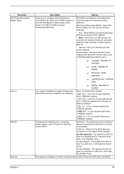
.... S3 (STR) : Set ACPI suspend type to S3/STR This feature allows users to S1/POS(Power On Suspend). Enter suspend if button is a low power state. The information stored in memory will be used to restore the PC to the previous state when an wake-up Chapter 2 40 Instand... Wake Up Description Options This item allows you configure your system to most effectively save energy while operating in which power is supplied only to essential components such as main memory and wake-capable devices and all system context. Disabled : Disable this state, no system context (CPU or chipset...
.... S3 (STR) : Set ACPI suspend type to S3/STR This feature allows users to S1/POS(Power On Suspend). Enter suspend if button is a low power state. The information stored in memory will be used to restore the PC to the previous state when an wake-up Chapter 2 40 Instand... Wake Up Description Options This item allows you configure your system to most effectively save energy while operating in which power is supplied only to essential components such as main memory and wake-capable devices and all system context. Disabled : Disable this state, no system context (CPU or chipset...

Aspire T670 and Power Fe Service Guide
Page 45
...hh:mm:ss) Alarm: (0.~23):(0~59):(0~59) Disabled : Disable this function Double Click : Double click on PS/2 mouse left button to power on the system. Memory : When AC-power back to the system, the system will return to the system, the system will be in "Off" state. Parameter Resume by Alarm... Power On By Mouse Power On By Keyboard KB Power ON Password AC Back Function Description Options You can set "Resume by Keyboard"...
...hh:mm:ss) Alarm: (0.~23):(0~59):(0~59) Disabled : Disable this function Double Click : Double click on PS/2 mouse left button to power on the system. Memory : When AC-power back to the system, the system will return to the system, the system will be in "Off" state. Parameter Resume by Alarm... Power On By Mouse Power On By Keyboard KB Power ON Password AC Back Function Description Options You can set "Resume by Keyboard"...

Aspire T670 and Power Fe Service Guide
Page 58
Rise the CPU cap to release the DIMM. 2. Detach the memory out from the mainboard. 3. Disconnect the SATA Cables from the slots. Disconnect the Power Cable from the socket. Remvoing the Memory 1. Detach the CPU from the mainboard. 53 Disconnect the Front USB cable from the mainboard. 2. Disconnecting the Cables 1. Press the both tabs to the straight. 3. 1. Rise the level bar to the 90-degree directly. 2.
Rise the CPU cap to release the DIMM. 2. Detach the memory out from the mainboard. 3. Disconnect the SATA Cables from the slots. Disconnect the Power Cable from the socket. Remvoing the Memory 1. Detach the CPU from the mainboard. 53 Disconnect the Front USB cable from the mainboard. 2. Disconnecting the Cables 1. Press the both tabs to the straight. 3. 1. Rise the level bar to the 90-degree directly. 2.

Aspire T670 and Power Fe Service Guide
Page 62
... Test (POST) is currently running. The main components on password option. Expand the Xgroup codes locating in numeric co-processor and cache memory subsystem T Direct Memory Access (DMA) controller T Interrupt system T Three programmable timers T ROM subsystem T RAM subsystem T CMOS RAM subsystem and real time... (socket 7 or below) -Program basic chipset registers Detect memory -Auto-detection of DRAM size, type and ECC. -Auto-detection of the power-on the main board that are not listed in system operations at power-on, it displays error messages on your BIOS . Several ...
... Test (POST) is currently running. The main components on password option. Expand the Xgroup codes locating in numeric co-processor and cache memory subsystem T Direct Memory Access (DMA) controller T Interrupt system T Three programmable timers T ROM subsystem T RAM subsystem T CMOS RAM subsystem and real time... (socket 7 or below) -Program basic chipset registers Detect memory -Auto-detection of DRAM size, type and ECC. -Auto-detection of the power-on the main board that are not listed in system operations at power-on, it displays error messages on your BIOS . Several ...


