
Aspire T690 User's Guide EN
Page 5
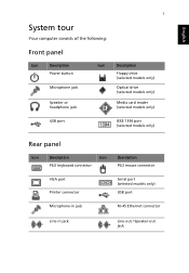
English 1 System tour Your computer consists of the following: Front panel Icon Description Power button Microphone jack Speaker or headphone jack Icon Description Floppy drive (selected models only) Optical drive (selected models only) Media card reader (selected models only) USB port IEEE 1394 port (selected models only) Rear panel Icon Description Icon PS/2 keyboard connector Description PS/2 mouse connector VGA port Printer connector Serial port (selected models only) USB port Microphone-in jack RJ-45 Ethernet connector Line-in jack Line-out / Speaker-out jack
English 1 System tour Your computer consists of the following: Front panel Icon Description Power button Microphone jack Speaker or headphone jack Icon Description Floppy drive (selected models only) Optical drive (selected models only) Media card reader (selected models only) USB port IEEE 1394 port (selected models only) Rear panel Icon Description Icon PS/2 keyboard connector Description PS/2 mouse connector VGA port Printer connector Serial port (selected models only) USB port Microphone-in jack RJ-45 Ethernet connector Line-in jack Line-out / Speaker-out jack
Aspire T690 User's Guide EN
Page 6
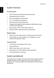
...; Power management functionality • 3.5" inch floppy drive (optional) • Multimedia card reader (optional) • CD-ROM, DVD-ROM, CD-RW (52X/24X), DVD/CD-RW combo or DVD writer (optional) • High-capacity, PATA / SATA HDD (optional) • Supports USB 2.0 high-performance peripherals Multimedia • Stereo-surround audio system via onboard audio controller • Audio-in/line-in, audio-out/line-out, headphone-out and external microphone-in jacks Connectivity • Two PS/2 ports for keyboard and mouse...
...; Power management functionality • 3.5" inch floppy drive (optional) • Multimedia card reader (optional) • CD-ROM, DVD-ROM, CD-RW (52X/24X), DVD/CD-RW combo or DVD writer (optional) • High-capacity, PATA / SATA HDD (optional) • Supports USB 2.0 high-performance peripherals Multimedia • Stereo-surround audio system via onboard audio controller • Audio-in/line-in, audio-out/line-out, headphone-out and external microphone-in jacks Connectivity • Two PS/2 ports for keyboard and mouse...

Aspire T690 User's Guide EN
Page 11
... voltage selector switch located on the rear panel of the computer is set to the correct voltage. • Check if you have properly plugged the power cable into an electrical outlet. • If you are possible situations that it is turned on. • Make sure the printer cable is connected securely to restart your dealer or the technical support center for assistance. If the LED is...
... voltage selector switch located on the rear panel of the computer is set to the correct voltage. • Check if you have properly plugged the power cable into an electrical outlet. • If you are possible situations that it is turned on. • Make sure the printer cable is connected securely to restart your dealer or the technical support center for assistance. If the LED is...
Aspire T670 and Power Fe Service Guide
Page 6
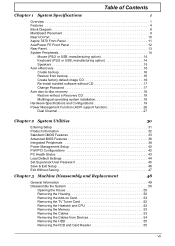
... 9 Rear I/O Port 10 Aspire T670 Front Panel 11 AcerPower FE Front Panel 12 Rear Panel 13 System Peripherals 14 Mouse (PS/2 or USB, manufacturing option 14 Keyboard (PS/2 or USB, manufacturing option 14 Speakers 15 Acer eRecovery 16 Create backup 16 Restore from backup 16 Create factory default image CD 16 Re-install bundled software without CD 17 Change Password 17 Acer disc-to-disc recovery 18 Restore without a Recovery CD 18 Multilingual operating system installation 18 Hardware Specifications and Configurations 19 Power Management Function (ACPI support function...
... 9 Rear I/O Port 10 Aspire T670 Front Panel 11 AcerPower FE Front Panel 12 Rear Panel 13 System Peripherals 14 Mouse (PS/2 or USB, manufacturing option 14 Keyboard (PS/2 or USB, manufacturing option 14 Speakers 15 Acer eRecovery 16 Create backup 16 Restore from backup 16 Create factory default image CD 16 Re-install bundled software without CD 17 Change Password 17 Acer disc-to-disc recovery 18 Restore without a Recovery CD 18 Multilingual operating system installation 18 Hardware Specifications and Configurations 19 Power Management Function (ACPI support function...
Aspire T670 and Power Fe Service Guide
Page 16
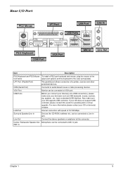
COM (Serial Port) Connects to this connector. Also make sure your OS supports USB controller. can be connected to VGA port. Line Out Connect the stereo speakers or earphone to serial-based mouse or data processing devices. LAN Port Internet connection with speed of a printer, scanner and other peripheral devices. Center / Subwoofer Speaker Out Microphone can be connected to MIC In jack. /MIC In Chapter 1 9 have a standard USB interface. USB Ports Before you connect your device(s) into USB connector(s), please make sure your device(s) such...
COM (Serial Port) Connects to this connector. Also make sure your OS supports USB controller. can be connected to VGA port. Line Out Connect the stereo speakers or earphone to serial-based mouse or data processing devices. LAN Port Internet connection with speed of a printer, scanner and other peripheral devices. Center / Subwoofer Speaker Out Microphone can be connected to MIC In jack. /MIC In Chapter 1 9 have a standard USB interface. USB Ports Before you connect your device(s) into USB connector(s), please make sure your device(s) such...

Aspire T670 and Power Fe Service Guide
Page 22
... optical device to store the backup disc image on CD or DVD (only available on screen to hard drive, CD, or DVD. Enter the password to proceed. In the Recovery settings window, select Burn image to open the Acer eRecovery utility. 3. In the Acer eRecovery window, select Recovery settings and click Next. 5. Acer eRecovery consists of the current system configuration to complete the process. Restore from hard drive, CD, or DVD. 1. Press + to quickly backup and restore the system. Acer...
... optical device to store the backup disc image on CD or DVD (only available on screen to hard drive, CD, or DVD. Enter the password to proceed. In the Recovery settings window, select Burn image to open the Acer eRecovery utility. 3. In the Acer eRecovery window, select Recovery settings and click Next. 5. Acer eRecovery consists of the current system configuration to complete the process. Restore from hard drive, CD, or DVD. 1. Press + to quickly backup and restore the system. Acer...
Aspire T670 and Power Fe Service Guide
Page 27
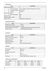
... drive Enable/Disable by BIOS Setup Serial Port Item Serial port controller Serial port controller resident bus Number of serial port Serial port location 16550 UART support Connector type Specification IT8712 LPC Bus 1 COM1 Yes 9-pin D-type female connector USB Port Item Universal HCI Controller Number of the connectors Location USB Class Specification USB 2.0/1.1 Intel ICH6 8 Rear : 4 On-board header : 4 Support legacy keyboard for legacy mode Wake-up Event Specifications Device Power Button PS2 Keyboard USB Keyboard S1 Enabled Enabled Disabled S3 Enabled Enabled Disabled S4 Enabled...
... drive Enable/Disable by BIOS Setup Serial Port Item Serial port controller Serial port controller resident bus Number of serial port Serial port location 16550 UART support Connector type Specification IT8712 LPC Bus 1 COM1 Yes 9-pin D-type female connector USB Port Item Universal HCI Controller Number of the connectors Location USB Class Specification USB 2.0/1.1 Intel ICH6 8 Rear : 4 On-board header : 4 Support legacy keyboard for legacy mode Wake-up Event Specifications Device Power Button PS2 Keyboard USB Keyboard S1 Enabled Enabled Disabled S3 Enabled Enabled Disabled S4 Enabled...

Aspire T670 and Power Fe Service Guide
Page 28
Wake-up Event Specifications RTC LAN Device S1 Enabled Enabled S3 Enabled Enabled S4 Enabled Enabled S5 Enabled Enabled Thermal Design Item Thermal Design Description T Dynamic FAN speed control by hardware monitor T CPU Over-temperature (over 120oC) power off protection Power On / Wake-up Event Item Power On/ Wake-Up Event Description T Power Button: S1/S3/S4/S5 T PS/2 Keyboard: S1/S3/S4/S5 T RTC: S1/S5 T LAN: S1/S3/S5 Memory Address Map Address 0000000 - 009FFFF 00A0000-00BFFFF...
Wake-up Event Specifications RTC LAN Device S1 Enabled Enabled S3 Enabled Enabled S4 Enabled Enabled S5 Enabled Enabled Thermal Design Item Thermal Design Description T Dynamic FAN speed control by hardware monitor T CPU Over-temperature (over 120oC) power off protection Power On / Wake-up Event Item Power On/ Wake-Up Event Description T Power Button: S1/S3/S4/S5 T PS/2 Keyboard: S1/S3/S4/S5 T RTC: S1/S5 T LAN: S1/S3/S5 Memory Address Map Address 0000000 - 009FFFF 00A0000-00BFFFF...
Aspire T670 and Power Fe Service Guide
Page 32
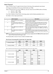
... of Intel chipset specifications. when three DDR memory modules are Pleae note that the Dual Channel Technology will operate when two memory installed ( the same memory size and modules are If you type) ? NOTE: We strongly recommend user to 4GB/s. memory module is The Dual Channel Technology can't operate when only one DDR installed ? Dual Channel Aspire T670/Acer Power F3 support the Dual Channel Technology. part of them will...
... of Intel chipset specifications. when three DDR memory modules are Pleae note that the Dual Channel Technology will operate when two memory installed ( the same memory size and modules are If you type) ? NOTE: We strongly recommend user to 4GB/s. memory module is The Dual Channel Technology can't operate when only one DDR installed ? Dual Channel Aspire T670/Acer Power F3 support the Dual Channel Technology. part of them will...
Aspire T670 and Power Fe Service Guide
Page 35
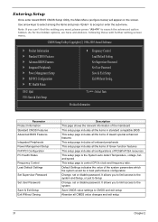
... Parameter Product Information Standard CMOS Features Advanced BIOS Features Integrated Peripherals Power Management Setup PnP/PCI Configuration PC Health Status Frequency Control Load Default Settings Set Supervisor Password Set User Password Save & Exit Setup Exit Without Saving Description This page shows the relevant information of the mainboard This setup page includes all the items in best performance configuration Change, set or disable password. It allows you to limit access to the system and...
... Parameter Product Information Standard CMOS Features Advanced BIOS Features Integrated Peripherals Power Management Setup PnP/PCI Configuration PC Health Status Frequency Control Load Default Settings Set Supervisor Password Set User Password Save & Exit Setup Exit Without Saving Description This page shows the relevant information of the mainboard This setup page includes all the items in best performance configuration Change, set or disable password. It allows you to limit access to the system and...
Aspire T670 and Power Fe Service Guide
Page 38
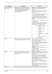
..., Slave IDE Device Setup. Options IDE HDD Auto-Detection Press [Enter] to the master port of IDE channel. None : No floppy drive installed 360K, 5.25" : 5.25 inch PC type standard drive ; 360Kbyte capacity 1.2M, 5.25" : 5.25 inch AT-type high-density drive; 1.2M byte capacity (3.5 inch when 3 Mode is determined by POST (Power On Self Test) of the BIOS. You can manually input the correct settings Access Mode : Use this to...
..., Slave IDE Device Setup. Options IDE HDD Auto-Detection Press [Enter] to the master port of IDE channel. None : No floppy drive installed 360K, 5.25" : 5.25 inch PC type standard drive ; 360Kbyte capacity 1.2M, 5.25" : 5.25 inch AT-type high-density drive; 1.2M byte capacity (3.5 inch when 3 Mode is determined by POST (Power On Self Test) of the BIOS. You can manually input the correct settings Access Mode : Use this to...

Aspire T670 and Power Fe Service Guide
Page 40
... the list. Press to load the disk ZIP, USB-FDD, USB-ZIP, USB- Advanced BIOS Features The following screen shows the Advanced BIOS Features: CMOS Setup Utility-Copyright (C) 1984-2005 Award Software Advanced BIOS Features Virus Warning CPU L1 & L2 Cache Silent Boot Configuration Table ` Hard Disk Boot Priority Quick Powr On Self Test First Boot Device Second Boot Device Third Boot Device Boot Other Device Boot Up NumLock Status Gate A20 Option Security Option # CPU Hyper-Threading Limit CPUID Max. Disabled : Disable this menu...
... the list. Press to load the disk ZIP, USB-FDD, USB-ZIP, USB- Advanced BIOS Features The following screen shows the Advanced BIOS Features: CMOS Setup Utility-Copyright (C) 1984-2005 Award Software Advanced BIOS Features Virus Warning CPU L1 & L2 Cache Silent Boot Configuration Table ` Hard Disk Boot Priority Quick Powr On Self Test First Boot Device Second Boot Device Third Boot Device Boot Other Device Boot Up NumLock Status Gate A20 Option Security Option # CPU Hyper-Threading Limit CPUID Max. Disabled : Disable this menu...
Aspire T670 and Power Fe Service Guide
Page 68
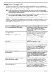
... hard drives require extra time to correct the problem by the change the Video selection. BIOS Messages BIOS ROM checksum error - defaults loaded CPU at nnnn Display switch is set incorrectly Press ESC to skip memory test Floppy disk(s) fail HARD DISK initializing - Contact your system dealer to replace the BIOS. A weak battery may indicate that no floppy drives are installed, be set to either turn off the system and change the jumper, or enter Setup and change . Displays the running speed of CMOS is...
... hard drives require extra time to correct the problem by the change the Video selection. BIOS Messages BIOS ROM checksum error - defaults loaded CPU at nnnn Display switch is set incorrectly Press ESC to skip memory test Floppy disk(s) fail HARD DISK initializing - Contact your system dealer to replace the BIOS. A weak battery may indicate that no floppy drives are installed, be set to either turn off the system and change the jumper, or enter Setup and change . Displays the running speed of CMOS is...
Aspire T670 and Power Fe Service Guide
Page 69
... IDE hard drive. BIOS Messages Keyboard Error Or No Keyboard Present Keyboard is attached correctly and no objects are pressed during POST. System OEMs may replace the Phoenix Technologies Award BIOS POST display with a set the error halt condition in the OEM display permits the operator to switch between the OEM display and the default POST display. Chapter 4 65 Unlock the key Memory Test: Memory test fail Override enabled - The BIOS then ignores the missing keyboard...
... IDE hard drive. BIOS Messages Keyboard Error Or No Keyboard Present Keyboard is attached correctly and no objects are pressed during POST. System OEMs may replace the Phoenix Technologies Award BIOS POST display with a set the error halt condition in the OEM display permits the operator to switch between the OEM display and the default POST display. Chapter 4 65 Unlock the key Memory Test: Memory test fail Override enabled - The BIOS then ignores the missing keyboard...

Aspire T670 and Power Fe Service Guide
Page 71
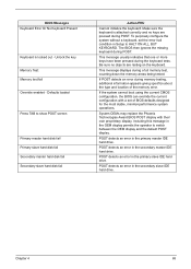
... drive 4. Main board Diskette drive LED fails to light, and the drive is unable to master connector or the drive is set correctly and its eject button is connected to access for more than 2 minutes when reading data. 1. Main board Hard Disk Drive NOTE: Ensure hard disk drive is configured correctly in BIOS Setup, cable/jumper are set correctly before diagnosing any hard disk drive problems. (If only one drive is installed, please make sure the drive is pressed and held. 1. CD/DVD-ROM drive CD/DVD-ROM drive LED flashes...
... drive 4. Main board Diskette drive LED fails to light, and the drive is unable to master connector or the drive is set correctly and its eject button is connected to access for more than 2 minutes when reading data. 1. Main board Hard Disk Drive NOTE: Ensure hard disk drive is configured correctly in BIOS Setup, cable/jumper are set correctly before diagnosing any hard disk drive problems. (If only one drive is installed, please make sure the drive is pressed and held. 1. CD/DVD-ROM drive CD/DVD-ROM drive LED flashes...

Aspire T670 and Power Fe Service Guide
Page 72
... is set to main board Video and Monitor Video memory test failed. Video adapter card 4. Monitor 3. CD/DVD-ROM drive. Speaker power/connection/cable. Remove all non-factory-installed cards. 2. Main board Audio Audio software program invokes but cannot receive/send data/ fax 1. If PCI modem card is inaccurate. 1. In Win 98, ensure the telephone application is readable). 3. Load default settings (if screen is configured correctly for your modem and set correctly. 2. For the External Modem, make sure Wake up the sound volume. 3. Ensure the CD/DVD-ROM driver...
... is set to main board Video and Monitor Video memory test failed. Video adapter card 4. Monitor 3. CD/DVD-ROM drive. Speaker power/connection/cable. Remove all non-factory-installed cards. 2. Main board Audio Audio software program invokes but cannot receive/send data/ fax 1. If PCI modem card is inaccurate. 1. In Win 98, ensure the telephone application is readable). 3. Load default settings (if screen is configured correctly for your modem and set correctly. 2. For the External Modem, make sure Wake up the sound volume. 3. Ensure the CD/DVD-ROM driver...

Aspire T670 and Power Fe Service Guide
Page 74
... power supply fan is properly installed. Ensure the printer driver is 1. Keyboard Some or all keys on the system. 1. Power switch cable assembly Pressing power switch does not turn off by PWR-BTTN. Power Supply not running. 2. Make sure that the LPT# or COM# you test is the same as the setting in BIOS Setup of the machine, just above the connector for the printer. Loop-back. 3. Load default settings. 2. Main board. Printer. 3. Refer to confirm ports...
... power supply fan is properly installed. Ensure the printer driver is 1. Keyboard Some or all keys on the system. 1. Power switch cable assembly Pressing power switch does not turn off by PWR-BTTN. Power Supply not running. 2. Make sure that the LPT# or COM# you test is the same as the setting in BIOS Setup of the machine, just above the connector for the printer. Loop-back. 3. Load default settings. 2. Main board. Printer. 3. Refer to confirm ports...
Aspire T670 and Power Fe Service Guide
Page 81
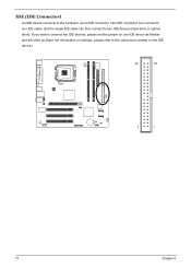
If you wish to connect two IDE devices, please set the jumper on one IDE cable, and the single IDE cable can connect to one IDE device as Master and the other as Slave (for information on settings, please refer to the instructions located on the IDE device). 40 39 AE 2 1 77 Chapter 5 One IDE connector can then connect to the computer via an IDE connector. IDE (IDE Connector) An IDE device connects to two IDE devices (hard drive or optical drive).
If you wish to connect two IDE devices, please set the jumper on one IDE cable, and the single IDE cable can connect to one IDE device as Master and the other as Slave (for information on settings, please refer to the instructions located on the IDE device). 40 39 AE 2 1 77 Chapter 5 One IDE connector can then connect to the computer via an IDE connector. IDE (IDE Connector) An IDE device connects to two IDE devices (hard drive or optical drive).
Aspire T670 and Power Fe Service Guide
Page 82
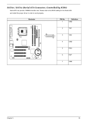
Please refer to the BIOS setting for the Serial ATA and install the proper driver in order to work properly. Illustrator PIN No. 1 Definition GND 2 TXP 1 3 TXN 7 4 GND 5 RXN AE 6 RXP 7 GND Chapter 5 78 SATA0 / SATA1 (Serial ATA Connector, Controlled by ICH6) Serial ATA can provide 150MB/s transfer rate.
Please refer to the BIOS setting for the Serial ATA and install the proper driver in order to work properly. Illustrator PIN No. 1 Definition GND 2 TXP 1 3 TXN 7 4 GND 5 RXN AE 6 RXP 7 GND Chapter 5 78 SATA0 / SATA1 (Serial ATA Connector, Controlled by ICH6) Serial ATA can provide 150MB/s transfer rate.
Power F6 User's Guide EN
Page 11
... printer cable is connected securely to the system's parallel port and the corresponding port on the screen. Q: The printer does not work , contact your computer. If yes, remove or replace it with a system floppy disk and press + + to turn the display back on . A: Do the following: • Make sure the printer is connected to a power outlet and that may arise during the use of the speakers...
... printer cable is connected securely to the system's parallel port and the corresponding port on the screen. Q: The printer does not work , contact your computer. If yes, remove or replace it with a system floppy disk and press + + to turn the display back on . A: Do the following: • Make sure the printer is connected to a power outlet and that may arise during the use of the speakers...


