
Power FV and Aspire T600 Service Guide
Page 6
... 1 Features 2 Aspire T600 Front Panel 4 Aspire T600 Rear Panel 5 Acer Power FV Front Panel 6 AcerPower FV Rear Panel 7 System Peripherals 8 MainBoard Layout 10 Block Diagram 11 Hardware Specifications and Configurations 12 Power Management Function (ACPI support function 20 Chapter 2 System Utilities 21 Entering Setup...CPU 45 Removing the MainBoard 46 Removing the Daughter Board 46 Disassembling the AcerPower FV 47 Opening the Housing 47 Removing the Front Panel 47 Removing the Cables 48 Removing the CD-ROM, FDD and HDD 49 Removing the System Fan 49 Removing the Power...
... 1 Features 2 Aspire T600 Front Panel 4 Aspire T600 Rear Panel 5 Acer Power FV Front Panel 6 AcerPower FV Rear Panel 7 System Peripherals 8 MainBoard Layout 10 Block Diagram 11 Hardware Specifications and Configurations 12 Power Management Function (ACPI support function 20 Chapter 2 System Utilities 21 Entering Setup...CPU 45 Removing the MainBoard 46 Removing the Daughter Board 46 Disassembling the AcerPower FV 47 Opening the Housing 47 Removing the Front Panel 47 Removing the Cables 48 Removing the CD-ROM, FDD and HDD 49 Removing the System Fan 49 Removing the Power...

Power FV and Aspire T600 Service Guide
Page 10
... Mouse Port T 1 Parallel Port, 1 Serial Port T 1 VGA Port T 1 LAN Port T 4 USB Ports T 6 Ports Jack Support HD audio output T On-board Connectors T 1 CPU Socket T 4 Memory DIMM T 1 PCI Express x1 Slot T 1 FDD Slot T 1 PATA IDE Slot T 2 SATA IDE Slots T 1 2*5 pin Intel FPIO Specification USB pin Connectors T... T 1 Aux in 4 pin Connector (CD-ROM Audio Input) T 1 3pin or 4 pin CPU Fan Connector T 1 24pin and 4 pin ATX Interface PS3/PS2 SPS Connector T 1 2*4pin Intel FPIO Specification Power Switch/Power State T LED/HDD Active LED T 1 2pin LAN Activity Monitor Connector T 2 Reserved 2pin GPIO ...
... Mouse Port T 1 Parallel Port, 1 Serial Port T 1 VGA Port T 1 LAN Port T 4 USB Ports T 6 Ports Jack Support HD audio output T On-board Connectors T 1 CPU Socket T 4 Memory DIMM T 1 PCI Express x1 Slot T 1 FDD Slot T 1 PATA IDE Slot T 2 SATA IDE Slots T 1 2*5 pin Intel FPIO Specification USB pin Connectors T... T 1 Aux in 4 pin Connector (CD-ROM Audio Input) T 1 3pin or 4 pin CPU Fan Connector T 1 24pin and 4 pin ATX Interface PS3/PS2 SPS Connector T 1 2*4pin Intel FPIO Specification Power Switch/Power State T LED/HDD Active LED T 1 2pin LAN Activity Monitor Connector T 2 Reserved 2pin GPIO ...

Power FV and Aspire T600 Service Guide
Page 17
... Item ATX1 ATX12V AUDIO1 BIOS_TBL BIOS_WP CDIN1 CLR_CMOS COM2 CPU SOCKET CPUFAN1 DIMM1~ DIMM4 FDD F_PANEL F_USB1 ~ F_USB2 IDE 1 PCI1 ~ PCI3 PCIE SATA1 ~ SATA2 SPK1 SYS_FAN 10 Description Standard 24-pin ATX power connector ATX12V power connector Front panel audio header BIOS TBL jumper BIOS flash... protect jumper Primary CD-in connector/ Auxiliary Audio input connector Clear CMOS jumper Onboard serial port header LGA775 socket for Pentium 4 CPUs CPU cooling fan connector Four 184-pin...
... Item ATX1 ATX12V AUDIO1 BIOS_TBL BIOS_WP CDIN1 CLR_CMOS COM2 CPU SOCKET CPUFAN1 DIMM1~ DIMM4 FDD F_PANEL F_USB1 ~ F_USB2 IDE 1 PCI1 ~ PCI3 PCIE SATA1 ~ SATA2 SPK1 SYS_FAN 10 Description Standard 24-pin ATX power connector ATX12V power connector Front panel audio header BIOS TBL jumper BIOS flash... protect jumper Primary CD-in connector/ Auxiliary Audio input connector Clear CMOS jumper Onboard serial port header LGA775 socket for Pentium 4 CPUs CPU cooling fan connector Four 184-pin...

Power FV and Aspire T600 Service Guide
Page 42
PC Health Status The following table describes the parameters found in this menu: Parameter CPU Shutdown Temperature Current CPU Temperature Current SYSTEM Temperature Current CPU / SYSTEM FAN Speed (RPM) Description Enables you to set the maximum temperature the system can reach before powering down. 60o C/140o F 65o C/149oF 70o C/158o F Disabled Detect CPU Temperature automatically Detect SYSTEM Temperature automatically Detect CPU/SYSTEM Fan Speed status automatically Chapter 2 35
PC Health Status The following table describes the parameters found in this menu: Parameter CPU Shutdown Temperature Current CPU Temperature Current SYSTEM Temperature Current CPU / SYSTEM FAN Speed (RPM) Description Enables you to set the maximum temperature the system can reach before powering down. 60o C/140o F 65o C/149oF 70o C/158o F Disabled Detect CPU Temperature automatically Detect SYSTEM Temperature automatically Detect CPU/SYSTEM Fan Speed status automatically Chapter 2 35

Power FV and Aspire T600 Service Guide
Page 51
...as highlight in yellow). 5. Disconnect the IDE cable. 7. Removing the TV Card 1. Removing the Power Supply 1. Remove the screws as highlight in red) and CPU fan cable (as shown here. Remove the main power connector as red circle shown. Remove the four screws as shown here. 2. 4. Pull out the ...CD-IN from TV card. 2. Then remove power supply. Disconnect the Power/HDD LED Cable and Power Switch Cable. then pull...
...as highlight in yellow). 5. Disconnect the IDE cable. 7. Removing the TV Card 1. Removing the Power Supply 1. Remove the screws as highlight in red) and CPU fan cable (as shown here. Remove the main power connector as red circle shown. Remove the four screws as shown here. 2. 4. Pull out the ...CD-IN from TV card. 2. Then remove power supply. Disconnect the Power/HDD LED Cable and Power Switch Cable. then pull...
Power FV and Aspire T600 Service Guide
Page 55
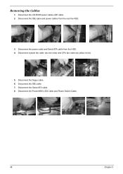
Removing the Cables 1. Disconnect the Power/HDD LED Cable and Power Switch Cable. 48 Chapter 3 Disconnect the CD-ROM power cables, IDE cable. 2. Disconnect system fan cable (as red circle) and CPU fan cable (as yellow circle). 5. Disconnect the Serial ATA cable. 8. Disconnect the IDE cable. 7. Disconnect the IDE cable and power cables from the HDD. 4. Disconnect the power cable and Serial ATA cable from the rear the FDD. 3. Disconnect the floppy cable. 6.
Removing the Cables 1. Disconnect the Power/HDD LED Cable and Power Switch Cable. 48 Chapter 3 Disconnect the CD-ROM power cables, IDE cable. 2. Disconnect system fan cable (as red circle) and CPU fan cable (as yellow circle). 5. Disconnect the Serial ATA cable. 8. Disconnect the IDE cable. 7. Disconnect the IDE cable and power cables from the HDD. 4. Disconnect the power cable and Serial ATA cable from the rear the FDD. 3. Disconnect the floppy cable. 6.

Power FV and Aspire T600 Service Guide
Page 56
Push on black track, and pull out CD-ROM as shown here. 2. Then remove the system fan. Removing the Power Supply 1. Then remove power supply. Push on black track, and pull out FDD as shown here. 2. Push on black track, and pull out HDD as red circle shown. Remove the four screws as shown here. Removing the System Fan Remove the four screws as shown here. 3. Removing the CD-ROM, FDD and HDD 1. Remove the CPU power connector as red circle shown. Remove the main power connector as shown here. 3. Chapter 3 49
Push on black track, and pull out CD-ROM as shown here. 2. Then remove the system fan. Removing the Power Supply 1. Then remove power supply. Push on black track, and pull out FDD as shown here. 2. Push on black track, and pull out HDD as red circle shown. Remove the four screws as shown here. Removing the System Fan Remove the four screws as shown here. 3. Removing the CD-ROM, FDD and HDD 1. Remove the CPU power connector as red circle shown. Remove the main power connector as shown here. 3. Chapter 3 49

Power FV and Aspire T600 Service Guide
Page 76
...indicator LEDs to ATX1. 6. CPUFA1/SYS_FAN: FAN Power Connectors Pin Signal Name 1 GND 2 +12V 3 Sense SPK1: Internal speaker Pin 1 2 3 4 Signal Buzzer Key VCC Signal Name Function System Ground Power +12V Sensor Chapter 5 69 Connecting Case Components... After you have installed the motherboard into a case, you can begin connecting the motherboard components. Connect the standard power supply connector to the F_PANEL. 5. Connect the case speaker cable to the following: 1. Refer to SPK1. 4. Connect the CPU cooling fan...
...indicator LEDs to ATX1. 6. CPUFA1/SYS_FAN: FAN Power Connectors Pin Signal Name 1 GND 2 +12V 3 Sense SPK1: Internal speaker Pin 1 2 3 4 Signal Buzzer Key VCC Signal Name Function System Ground Power +12V Sensor Chapter 5 69 Connecting Case Components... After you have installed the motherboard into a case, you can begin connecting the motherboard components. Connect the standard power supply connector to the F_PANEL. 5. Connect the case speaker cable to the following: 1. Refer to SPK1. 4. Connect the CPU cooling fan...

Power FV and Aspire T600 Service Guide
Page 87
Microsoft Windows XP Home Environment Test Item Mother Board ECS Processor Intel Retention Module Foxconn Cooler Foxconn System Fan Sunon Memory-DDR333 Infineon Nanya Memory-DDR400 Infineon Nanya Micron Apacer HDD-SATA Seagate WD DVD-ROM Lite-On CD...800FSB) P4 520 (2.8G 1M 800FSB) 505-Prescott 2.66GHz JM80547PG0881M JM80547PG0801M JM80547PG0721M JM80547PE0671M RM For Socket T For 775 CPU Cooler FXC heatsink (PKP219GB1U12) + Sunon Fan (PMD1208PKV1-A) 4300RPM Sunon 92X92X25mm 2200RPM System Fan KDE1209PTV3 DDR 333 256MB 0.11u (black) DDR 333 512MB 0.11u (black) DDR 333 128MB 0.11u DDR 333 ...
Microsoft Windows XP Home Environment Test Item Mother Board ECS Processor Intel Retention Module Foxconn Cooler Foxconn System Fan Sunon Memory-DDR333 Infineon Nanya Memory-DDR400 Infineon Nanya Micron Apacer HDD-SATA Seagate WD DVD-ROM Lite-On CD...800FSB) P4 520 (2.8G 1M 800FSB) 505-Prescott 2.66GHz JM80547PG0881M JM80547PG0801M JM80547PG0721M JM80547PE0671M RM For Socket T For 775 CPU Cooler FXC heatsink (PKP219GB1U12) + Sunon Fan (PMD1208PKV1-A) 4300RPM Sunon 92X92X25mm 2200RPM System Fan KDE1209PTV3 DDR 333 256MB 0.11u (black) DDR 333 512MB 0.11u (black) DDR 333 128MB 0.11u DDR 333 ...


