
Aspire SA85/Power S285 User's Guide EN
Page 6
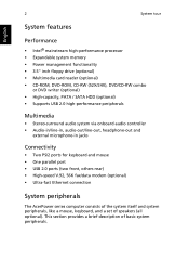
2 System tour English System features Performance • Intel® mainstream high-performance processor • Expandable system memory • Power management functionality • 3.5" inch floppy drive (optional) • Multimedia card reader (optional) • CD-ROM, DVD-ROM, CD-RW (52X/24X), DVD/CD-RW combo ...
2 System tour English System features Performance • Intel® mainstream high-performance processor • Expandable system memory • Power management functionality • 3.5" inch floppy drive (optional) • Multimedia card reader (optional) • CD-ROM, DVD-ROM, CD-RW (52X/24X), DVD/CD-RW combo ...
Aspire SA85/Power S285 User's Guide EN
Page 10
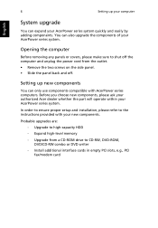
... outlet. • Remove the two screws on the side panel. • Slide the panel back and off the computer and unplug the power cord from a CD-ROM drive to the instructions provided with AcerPower series computers. Install additional interface cards in empty PCI slots, e.g., PCI ... components of your AcerPower series system. Before you choose new components, please ask your authorized Acer dealer whether the part will operate within your AcerPower series system. Expand high-level memory - 6 Setting up new components You can only use components compatible with your new components....
... outlet. • Remove the two screws on the side panel. • Slide the panel back and off the computer and unplug the power cord from a CD-ROM drive to the instructions provided with AcerPower series computers. Install additional interface cards in empty PCI slots, e.g., PCI ... components of your AcerPower series system. Before you choose new components, please ask your authorized Acer dealer whether the part will operate within your AcerPower series system. Expand high-level memory - 6 Setting up new components You can only use components compatible with your new components....
Aspire T680 and Power FG Service Guide
Page 5
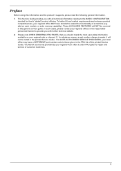
... have a DIFFERENT part number code to -date information available on card, modem, or extra memory capability). For ACER-AUTHORIZED SERVICE PROVIDERS, your regional Acer office to the BASIC CONFIGURATION decided for Acer's "global" product offering. This Service Guide provides you should check the most up-to those... of customer machines. If, for repair and service of this generic service guide. You MUST use the list provided by your Acer office may have decided to provide you with all technical information relating to order FRU parts for whatever reason, a part number change...
... have a DIFFERENT part number code to -date information available on card, modem, or extra memory capability). For ACER-AUTHORIZED SERVICE PROVIDERS, your regional Acer office to the BASIC CONFIGURATION decided for Acer's "global" product offering. This Service Guide provides you should check the most up-to those... of customer machines. If, for repair and service of this generic service guide. You MUST use the list provided by your Acer office may have decided to provide you with all technical information relating to order FRU parts for whatever reason, a part number change...
Aspire T680 and Power FG Service Guide
Page 8
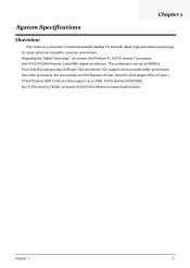
..., Intel 915GV+ICH6 (Prescott/ Cedar Mill) chipset architecture. We also provide one PCI-Express x16 slot, three PCI slots (support PCI 2.2 spec.), 4 Dual Channel DDR 2 memory slots (support up to 4GB), P-ATA devices (HDD/ODD), four S-ATA devices (HDDs), on board 10/100/1000 LAN and on board Audio function. This...
..., Intel 915GV+ICH6 (Prescott/ Cedar Mill) chipset architecture. We also provide one PCI-Express x16 slot, three PCI slots (support PCI 2.2 spec.), 4 Dual Channel DDR 2 memory slots (support up to 4GB), P-ATA devices (HDD/ODD), four S-ATA devices (HDDs), on board 10/100/1000 LAN and on board Audio function. This...

Aspire T680 and Power FG Service Guide
Page 9
... ~3.8GHz speed Celeron D 2.53GHz ~ 3.2GHz L2 Cache varies with CPU from 1MB to 2MB Chipset T Northbridge: Intel 915GV T Southbridge: ICH6 Memory T Socket Type : DDR2 , 1.8 Voltage T Socket Quantity : 2 T Capacity support : 128MB ~ 4GB T Support Memory Speed : 533/400 MHz Graphic Solution T Integrated VGA T ATI x300, x600 T nVidia 6600 Slots T T 3 PCI slot 1 PCIE 16x slot...
... ~3.8GHz speed Celeron D 2.53GHz ~ 3.2GHz L2 Cache varies with CPU from 1MB to 2MB Chipset T Northbridge: Intel 915GV T Southbridge: ICH6 Memory T Socket Type : DDR2 , 1.8 Voltage T Socket Quantity : 2 T Capacity support : 128MB ~ 4GB T Support Memory Speed : 533/400 MHz Graphic Solution T Integrated VGA T ATI x300, x600 T nVidia 6600 Slots T T 3 PCI slot 1 PCIE 16x slot...

Aspire T680 and Power FG Service Guide
Page 12
... T 1 Parallel Port, 1 Serial Port T 1 VGA Port T 1 10/100/1000 LAN Port T 4 USB Ports T 1 Line-in/Line-out/Mic-in port T On-Board Connectos T 1 CPU Socket T 4 Memory Slots T 1 PCI Express x16 Slot T 3 PCI Slots T 1 FDD Slot T 1 PATA IDE Slots T 4 SATA IDE Slots T 1 2*5 pin USB pin connector T 1 serial port pin connector (2nd serial...
... T 1 Parallel Port, 1 Serial Port T 1 VGA Port T 1 10/100/1000 LAN Port T 4 USB Ports T 1 Line-in/Line-out/Mic-in port T On-Board Connectos T 1 CPU Socket T 4 Memory Slots T 1 PCI Express x16 Slot T 3 PCI Slots T 1 FDD Slot T 1 PATA IDE Slots T 4 SATA IDE Slots T 1 2*5 pin USB pin connector T 1 serial port pin connector (2nd serial...
Aspire T680 and Power FG Service Guide
Page 24
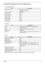
Chapter 1 17 Hardware Specifications and Configurations System Board Major Chip Item System Core Logic Super I/O Controller LAN Controller Memory Controller E-IDE Controller SATA Controller RJ45 Controller Audio Controller VGA Controller Specification Northbridge : Intel 915GV Southbridge : Intel ICH6 W83627THF ICH6 915GV ICH6 ICH6 ICH6 ALC880 ...
Chapter 1 17 Hardware Specifications and Configurations System Board Major Chip Item System Core Logic Super I/O Controller LAN Controller Memory Controller E-IDE Controller SATA Controller RJ45 Controller Audio Controller VGA Controller Specification Northbridge : Intel 915GV Southbridge : Intel ICH6 W83627THF ICH6 915GV ICH6 ICH6 ICH6 ALC880 ...
Aspire T680 and Power FG Service Guide
Page 25
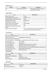
... scheme Fixed in any combination as long as they match the above specifications. System Memory Item Memory Slot Number Supported Memory Size per Slot Supported Maximum total Memory Size Supported Memory Speed Supported memory voltage Support memory module package Support to parity check feature Support to enter BIOS Setup Utility. BIOS... Hotkey c Function Enter BIOS Setup Utility Description Press while the system is booting to Error Correction Code (ECC) feature Memory module combinations 4 slots 128 MB ~ 1GB 4GB 533/400 MHz 1.8 V 240-pin DIMM Yes Yes Specification You can install...
... scheme Fixed in any combination as long as they match the above specifications. System Memory Item Memory Slot Number Supported Memory Size per Slot Supported Maximum total Memory Size Supported Memory Speed Supported memory voltage Support memory module package Support to parity check feature Support to enter BIOS Setup Utility. BIOS... Hotkey c Function Enter BIOS Setup Utility Description Press while the system is booting to Error Correction Code (ECC) feature Memory module combinations 4 slots 128 MB ~ 1GB 4GB 533/400 MHz 1.8 V 240-pin DIMM Yes Yes Specification You can install...
Aspire T680 and Power FG Service Guide
Page 27
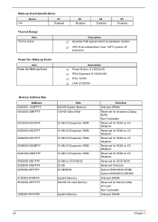
... / Wake-up Event Item Power On/ Wake-Up Event Description T Power Button: S1/S3/S4/S5 T PS/2 Keyboard: S1/S3/S4/S5 T RTC: S1/S5 T LAN: S1/S3/S5 Memory Address Map Address 0000000 - 009FFFF 00A0000-00BFFFF 00C0000-00CFFFF 00D0000-00D3FFF 00D4000-00D7FFF 00D8000-00DBFFF 00DC000-00DFFFF 00E0000-... Expansion ROM 16 KB I/O Expansion ROM 16 KB I/O Expansion ROM 32 KB for SCSI BIOS 32 KB 64 KB BIOS System Memory 384 KB I/O Card Memory System Memory Function Onboard DRAM Reserved for Graphics Display Buffer Non-Cacheable Reserved for ROM on I/O Adapters Reserved for ROM on I/O Adapters Reserved ...
... / Wake-up Event Item Power On/ Wake-Up Event Description T Power Button: S1/S3/S4/S5 T PS/2 Keyboard: S1/S3/S4/S5 T RTC: S1/S5 T LAN: S1/S3/S5 Memory Address Map Address 0000000 - 009FFFF 00A0000-00BFFFF 00C0000-00CFFFF 00D0000-00D3FFF 00D4000-00D7FFF 00D8000-00DBFFF 00DC000-00DFFFF 00E0000-... Expansion ROM 16 KB I/O Expansion ROM 16 KB I/O Expansion ROM 32 KB for SCSI BIOS 32 KB 64 KB BIOS System Memory 384 KB I/O Card Memory System Memory Function Onboard DRAM Reserved for Graphics Display Buffer Non-Cacheable Reserved for ROM on I/O Adapters Reserved for ROM on I/O Adapters Reserved ...
Aspire T680 and Power FG Service Guide
Page 45
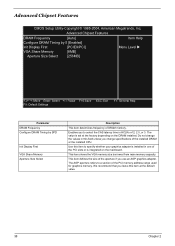
...American Megatrends, Inc, Advanced Chipset Features DRAM Frequency [Auto] Item Help Configure DRAM Timing by S [Enabled] Init Display First [PCIEX/PCI] VGA Share Memory [8MB] Menu Level X Aperture Size Select [256MB] KLIJ: Move Enter: Select +/-/: Value F10:Save ESC: Exit F9: Default Settings F1: General... Help Parameter DRAM Frequency Configure DRAM Timing by SPD Init Display First VGA Share Memory Aperture Size Select Description This item determines frequency of the installed DRAM or the installed CPU. Do not change the values in ...
...American Megatrends, Inc, Advanced Chipset Features DRAM Frequency [Auto] Item Help Configure DRAM Timing by S [Enabled] Init Display First [PCIEX/PCI] VGA Share Memory [8MB] Menu Level X Aperture Size Select [256MB] KLIJ: Move Enter: Select +/-/: Value F10:Save ESC: Exit F9: Default Settings F1: General... Help Parameter DRAM Frequency Configure DRAM Timing by SPD Init Display First VGA Share Memory Aperture Size Select Description This item determines frequency of the installed DRAM or the installed CPU. Do not change the values in ...
Aspire T680 and Power FG Service Guide
Page 48
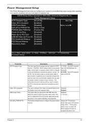
...is independent from the power states previously described in memory will be used to restore the PC to configure the power button function. In this section (Standby and Suspend). S3 (STR): The S3 sleep mode is s power-down when Disabled the system is saved to power off by Alarm [Disabled...only to essential components such as main memory and wake-capable devices and all system context. to main memory. S1(POS): The S1 sleep mode is pressed less than 4 sec. Instand-off : Press down button then power off instantly Delay 4 Sec. : Press power button 4 sec. Disabled 1~15 ...
...is independent from the power states previously described in memory will be used to restore the PC to configure the power button function. In this section (Standby and Suspend). S3 (STR): The S3 sleep mode is s power-down when Disabled the system is saved to power off by Alarm [Disabled...only to essential components such as main memory and wake-capable devices and all system context. to main memory. S1(POS): The S1 sleep mode is pressed less than 4 sec. Instand-off : Press down button then power off instantly Delay 4 Sec. : Press power button 4 sec. Disabled 1~15 ...

Aspire T680 and Power FG Service Guide
Page 62
Detach the memory out from the chassis. 3. Detach the USB module from the slot. Detach the CPU from the mainboard. 3. Pop up the tabs on each corner. 2. Removing the USB Module 1. Removing the Heatsink and CPU 1. Lift the clip. 5. Detach the Heatsink from the socket. 55 Press down to detach the daughter board. Disconnect the cables and loosen the two screws to release the CPU lever. 4. Lift the cover. 6. Remove the one screw. 2. Loosn those fore screws on both side. 2. Removing the DIMM 1.
Detach the memory out from the chassis. 3. Detach the USB module from the slot. Detach the CPU from the mainboard. 3. Pop up the tabs on each corner. 2. Removing the USB Module 1. Removing the Heatsink and CPU 1. Lift the clip. 5. Detach the Heatsink from the socket. 55 Press down to detach the daughter board. Disconnect the cables and loosen the two screws to release the CPU lever. 4. Lift the cover. 6. Remove the one screw. 2. Loosn those fore screws on both side. 2. Removing the DIMM 1.
Aspire T680 and Power FG Service Guide
Page 65
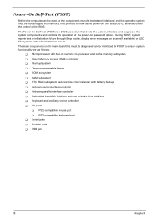
...system components, and controls the operation of the power-on Self test(POST), generally under the control of the BIOS. The Power-On Self Test (POST) is know as follows: T Microprocessor with built-in numeric co-processor and cache memory subsystem T Direct Memory Access (DMA) controller T Interrupt system T ... This process is a BIOS procedure that must be diagnosed and/or initialized by POST to ensure system functionality are as the power-on password option. Power-On Self-Test (POST) Before the computer can be used, all the components must be tested and initialized, and the...
...system components, and controls the operation of the power-on Self test(POST), generally under the control of the BIOS. The Power-On Self Test (POST) is know as follows: T Microprocessor with built-in numeric co-processor and cache memory subsystem T Direct Memory Access (DMA) controller T Interrupt system T ... This process is a BIOS procedure that must be diagnosed and/or initialized by POST to ensure system functionality are as the power-on password option. Power-On Self-Test (POST) Before the computer can be used, all the components must be tested and initialized, and the...
Aspire T680 and Power FG Service Guide
Page 66
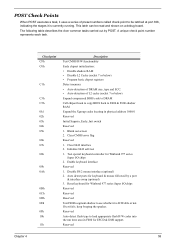
...speaker. Blank out screen 2. Auto detect ports for Winbond 977 series Super I /O chips 2. Reserved Chapter 4 59 The following table describes the Acer common tasks carried out by a port & interface swap (optional) 3. Test special keyboard controller for ESCD & DMI support. Checkpoint CFh C0h C1h...Early chipset initialization: • Disable shadow RAM • Disable L2 Cache (socket 7 or below) • Program basic chipset registers Detect memory • Auto-detection of DRAM size, type and ECC. • Auto-detection of preset numbers called check point to be read and shown...
...speaker. Blank out screen 2. Auto detect ports for Winbond 977 series Super I /O chips 2. Reserved Chapter 4 59 The following table describes the Acer common tasks carried out by a port & interface swap (optional) 3. Test special keyboard controller for ESCD & DMI support. Checkpoint CFh C0h C1h...Early chipset initialization: • Disable shadow RAM • Disable L2 Cache (socket 7 or below) • Program basic chipset registers Detect memory • Auto-detection of DRAM size, type and ECC. • Auto-detection of preset numbers called check point to be read and shown...

Aspire T680 and Power FG Service Guide
Page 67
... legacy information. See also POST 26h. Early PCI Initialization: • Enumerate PCI bus number • Assign memory & I/O resource • Search for 0-640K memory address. 2. Initialize the APIC for override. Chipset default values are directed to SPURIOUS_INT_HDLR & S/W interrupts to CMOS... setup. Load CMOS settings into chipset. Example: onboard IDE controller. 4. Also set real-time clock power status, and then check...
... legacy information. See also POST 26h. Early PCI Initialization: • Enumerate PCI bus number • Assign memory & I/O resource • Search for 0-640K memory address. 2. Initialize the APIC for override. Chipset default values are directed to SPURIOUS_INT_HDLR & S/W interrupts to CMOS... setup. Load CMOS settings into chipset. Example: onboard IDE controller. 4. Also set real-time clock power status, and then check...

Aspire T680 and Power FG Service Guide
Page 68
... for channel 1 Reserved Test 8259 interrupt mask bits for AMD K5 CPU. Reserved Rederved Reserved Reserved Reserved Reset keyboard if Early_Reset_KB is defined e.g. Calculate total memory by testing the last double word of each 64K page. 2. Winbond 977 series Super I/O chips. Checkpoint 2Ah 2Bh 2Ch 2Dh 2Eh 2Fh 30h 31h 32h...
... for channel 1 Reserved Test 8259 interrupt mask bits for AMD K5 CPU. Reserved Rederved Reserved Reserved Reserved Reset keyboard if Early_Reset_KB is defined e.g. Calculate total memory by testing the last double word of each 64K page. 2. Winbond 977 series Super I/O chips. Checkpoint 2Ah 2Bh 2Ch 2Dh 2Eh 2Fh 30h 31h 32h...

Aspire T680 and Power FG Service Guide
Page 69
...6Bh 6Ch Description 1. Program MTRR of processors (multi-processor platform) Reserved 1. Reserved Initialize USB Keyboard & Mouse Reserved Test all memory (clear all extended memory to 0) Clear password according to items described in case the cacheable ranges between each CPU are not identical. Reserved Initialize PS/2... Mouse Reserved Prepare memory size information for P6 class CPU. 4. Initialize the APIC for function call: INT 15h ax=E820h Reserved Turn on L2 cache...
...6Bh 6Ch Description 1. Program MTRR of processors (multi-processor platform) Reserved 1. Reserved Initialize USB Keyboard & Mouse Reserved Test all memory (clear all extended memory to 0) Clear password according to items described in case the cacheable ranges between each CPU are not identical. Reserved Initialize PS/2... Mouse Reserved Prepare memory size information for P6 class CPU. 4. Initialize the APIC for function call: INT 15h ax=E820h Reserved Turn on L2 cache...

Aspire T680 and Power FG Service Guide
Page 70
...to "Auto". Initialize floppy controller 2. If no errors occur or F1 key is set to continue: Clear EPA or customization logo. Call chipset power management hook. 2. USB final initialization 2. Assign IRQs to CMOS Initialize ISA PnP boot devices 1. Reserved 1. Recover the text fond used by ...EPA logo (not for keys - ALT+F2 is supported. - Set up ACPI table at top of the memory. Detect serial ports & parallel ports Reserved Reserved Detect & install co-processor Reserved Init HDD write protect Reserved Reserved Switch back to all IDE device...
...to "Auto". Initialize floppy controller 2. If no errors occur or F1 key is set to continue: Clear EPA or customization logo. Call chipset power management hook. 2. USB final initialization 2. Assign IRQs to CMOS Initialize ISA PnP boot devices 1. Reserved 1. Recover the text fond used by ...EPA logo (not for keys - ALT+F2 is supported. - Set up ACPI table at top of the memory. Detect serial ports & parallel ports Reserved Reserved Detect & install co-processor Reserved Init HDD write protect Reserved Reserved Switch back to all IDE device...
Aspire T680 and Power FG Service Guide
Page 72
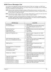
...2. BIOS Messages I/O Parity Error CPU Clock Mismatch Real Time Clock Error CMOS Battery Bad CMOS Checksum Error Equipment Configuration Error System Management Memory Bad Memory Error at MMMM:SSSS:OOOOh RAM Parity Error PS/2 Keyboard Error or Keyboard Not Connected PS/2 Keyboard Interface Error PS/2 Keyboard Locked ...BIOS Setup to ensure that are NOT factory- Re-connect PS/2 keyboard and mouse. 2. PS/2 keyboard 4. PS/2 mouse 5. Remove all power supply voltages, switch, and jumper settings before you have deemed it necessary to replace an FRU, and have a "system no other activity...
...2. BIOS Messages I/O Parity Error CPU Clock Mismatch Real Time Clock Error CMOS Battery Bad CMOS Checksum Error Equipment Configuration Error System Management Memory Bad Memory Error at MMMM:SSSS:OOOOh RAM Parity Error PS/2 Keyboard Error or Keyboard Not Connected PS/2 Keyboard Interface Error PS/2 Keyboard Locked ...BIOS Setup to ensure that are NOT factory- Re-connect PS/2 keyboard and mouse. 2. PS/2 keyboard 4. PS/2 mouse 5. Remove all power supply voltages, switch, and jumper settings before you have deemed it necessary to replace an FRU, and have a "system no other activity...
Aspire T680 and Power FG Service Guide
Page 73
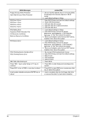
Load default settings in Setup. 2. IDE hard disk drive power. 4. IDE hard disk drive cable/connection. 5. Enter BIOS Setup and set the Reset Resource Assignments of the PnP/PCI Options to Yes, then reboot the ... Disk Drive(s) Write Protected IDE Drive 0 Error IDE Drive 1 Error IDE Drive 2 Error IDE Drive 3 Error IRQ Setting Error Expansion ROM Allocation Fail I/O Resource Conflict(s) Memory Resource Conflict(s) PCI Device Error PS/2 Pointing Device Interface Error PS/2 Pointing Device Error DMI Table Was Destroyed Press "DEL" key to enter Setup or...
Load default settings in Setup. 2. IDE hard disk drive power. 4. IDE hard disk drive cable/connection. 5. Enter BIOS Setup and set the Reset Resource Assignments of the PnP/PCI Options to Yes, then reboot the ... Disk Drive(s) Write Protected IDE Drive 0 Error IDE Drive 1 Error IDE Drive 2 Error IDE Drive 3 Error IRQ Setting Error Expansion ROM Allocation Fail I/O Resource Conflict(s) Memory Resource Conflict(s) PCI Device Error PS/2 Pointing Device Interface Error PS/2 Pointing Device Error DMI Table Was Destroyed Press "DEL" key to enter Setup or...


