

Power F1/ Aspire T310 Service Guide
Page 3
Revision History Please refer to the table below for the updates made on AcerPower F1/Aspire T310 service guide. 2003/10/29 Date 2003/12/18 Chapter 1 Chapter Chapter 1 Updates > Amend the FSB speed up to 800MHz on page 2 > Memory portion > Memory combination portion >Amend the Rear Panel and mainboard layout without SATA II
Revision History Please refer to the table below for the updates made on AcerPower F1/Aspire T310 service guide. 2003/10/29 Date 2003/12/18 Chapter 1 Chapter Chapter 1 Updates > Amend the FSB speed up to 800MHz on page 2 > Memory portion > Memory combination portion >Amend the Rear Panel and mainboard layout without SATA II

Power F1/ Aspire T310 Service Guide
Page 6
...your Acer office may have decided to extend the functionality of a machine (e.g. You MUST use the list provided by your regional offices or the responsible personnel/channel to provide you with all technical information relating to -date information available on card, modem, or extra memory ... market requirements and enhance product competitiveness, your regional web or channel. Preface Before using this generic service guide. If, for Acer's "global" product offering. V Please note WHEN ORDERING FRU PARTS, that you with further technical details. 2. In such cases, please ...
...your Acer office may have decided to extend the functionality of a machine (e.g. You MUST use the list provided by your regional offices or the responsible personnel/channel to provide you with all technical information relating to -date information available on card, modem, or extra memory ... market requirements and enhance product competitiveness, your regional web or channel. Preface Before using this generic service guide. If, for Acer's "global" product offering. V Please note WHEN ORDERING FRU PARTS, that you with further technical details. 2. In such cases, please ...
Power F1/ Aspire T310 Service Guide
Page 10
..., your regional offices or the responsible personnel/channel to provide you with all technical information relating to the BASIC CONFIGURATION decided for Acer's "global" product offering. In such cases, please contact your regional office MAY have a DIFFERENT part number code to order ... LOCALIZED FEATURES will not be covered in this generic service guide. add-on your Acer office may have decided to -date information available on card, modem, or extra memory capability). For ACER-AUTHORIZED SERVICE PROVIDERS, your regional web or channel. V This Service Guide provides you...
..., your regional offices or the responsible personnel/channel to provide you with all technical information relating to the BASIC CONFIGURATION decided for Acer's "global" product offering. In such cases, please contact your regional office MAY have a DIFFERENT part number code to order ... LOCALIZED FEATURES will not be covered in this generic service guide. add-on your Acer office may have decided to -date information available on card, modem, or extra memory capability). For ACER-AUTHORIZED SERVICE PROVIDERS, your regional web or channel. V This Service Guide provides you...
Power F1/ Aspire T310 Service Guide
Page 12
Table of Contents Chapter 1 System Specifications 1 Overview 1 Features & Specification 2 Acer Power F1 Front Panel 4 Acer Power F1 Rear Panel 5 Aspire T310/Acer Power F1 Front Panel 6 Hardware Specifications and Configurations 8 Power Management Function (ACPI support function 16 Chapter 2 System Utilities 17 Entering Setup 18 ... Daughter Board 50 Installing the LED Module 50 Installing the Power Button 50 Installing the Mainboard 50 Installing the Heatsink and the CPU 51 Installing the Memory 51 Installing the Power Supply 52 Installing the Modem card,CD-ROM, Floppy and...
Table of Contents Chapter 1 System Specifications 1 Overview 1 Features & Specification 2 Acer Power F1 Front Panel 4 Acer Power F1 Rear Panel 5 Aspire T310/Acer Power F1 Front Panel 6 Hardware Specifications and Configurations 8 Power Management Function (ACPI support function 16 Chapter 2 System Utilities 17 Entering Setup 18 ... Daughter Board 50 Installing the LED Module 50 Installing the Power Button 50 Installing the Mainboard 50 Installing the Heatsink and the CPU 51 Installing the Memory 51 Installing the Power Supply 52 Installing the Modem card,CD-ROM, Floppy and...

Power F1/ Aspire T310 Service Guide
Page 15
...: AC Link Channel: 6 Connectors support: T Line-in/Line-out (rear) 2 Chapter 1 Features & Specifications CPU T T T T Support Intel P4 Northwood (Socket 478) processor. Chipset T SiS 661FX, SiS964L Memory T Socket Type: DDR-SDRAM PC2700/PC2100/PC3200(DDR400) 184-pin socket. T Total: 64MB ~ 2GB (please refer to 3.06GHz+ P4 processor.
...: AC Link Channel: 6 Connectors support: T Line-in/Line-out (rear) 2 Chapter 1 Features & Specifications CPU T T T T Support Intel P4 Northwood (Socket 478) processor. Chipset T SiS 661FX, SiS964L Memory T Socket Type: DDR-SDRAM PC2700/PC2100/PC3200(DDR400) 184-pin socket. T Total: 64MB ~ 2GB (please refer to 3.06GHz+ P4 processor.

Power F1/ Aspire T310 Service Guide
Page 22
... (4 banks) 64MB / 128MB / 256MB/ 512MB/1G 1G x2 DDR SDRAM DDR400/333/266 2.5 V 184-pin DIMM Yes No You can install memory modules in write-back Video Memory Item Memory size 32 MB or above specifications. Memory Combinations Slot 1 Slot 2 Slot Memory Module 64, 128, 256, 512MB, 1G 64, 128, 256, 512MB, 1G Maximum System...
... (4 banks) 64MB / 128MB / 256MB/ 512MB/1G 1G x2 DDR SDRAM DDR400/333/266 2.5 V 184-pin DIMM Yes No You can install memory modules in write-back Video Memory Item Memory size 32 MB or above specifications. Memory Combinations Slot 1 Slot 2 Slot Memory Module 64, 128, 256, 512MB, 1G 64, 128, 256, 512MB, 1G Maximum System...
Power F1/ Aspire T310 Service Guide
Page 30
... values in CMOS. The system reboots immediately after you have saved all open files. There is not part of the system RAM. Chapter 2 17 This memory area is no need to run Setup, make sure that you exit Setup. Before you run Setup when starting the computer unless you repeatedly receive.... Chapter 2 System Utilities Most systems are already configured by the manufacturer or the dealer. The Setup program loads configuration values into the battery-backed nonvolatile memory called CMOS RAM.
... values in CMOS. The system reboots immediately after you have saved all open files. There is not part of the system RAM. Chapter 2 17 This memory area is no need to run Setup, make sure that you exit Setup. Before you run Setup when starting the computer unless you repeatedly receive.... Chapter 2 System Utilities Most systems are already configured by the manufacturer or the dealer. The Setup program loads configuration values into the battery-backed nonvolatile memory called CMOS RAM.

Power F1/ Aspire T310 Service Guide
Page 34
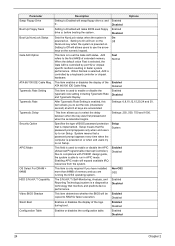
... the system stops in case of Power On Self Test errors (POST). To enter the IDE Channel 1 Slave setup, press [Enter]. VGA/EGA CGA40 CGA80 Mono This parameter enables you to the slave port of memory that DOS supports. Extended memory is not configured in PCs with ...1MB of IDE channel 1. Parameter IDE Channel 1 Master IDE Channel 1 Slave Drive A Drive B Floppy 3 Mode Support Video Halt On Base Memory Extended Memory Total Memory Description Options Allows you to configure the hard disk drive connected to the system. To enter the IDE Channel 1 Master setup, press [Enter...
... the system stops in case of Power On Self Test errors (POST). To enter the IDE Channel 1 Slave setup, press [Enter]. VGA/EGA CGA40 CGA80 Mono This parameter enables you to the slave port of memory that DOS supports. Extended memory is not configured in PCs with ...1MB of IDE channel 1. Parameter IDE Channel 1 Master IDE Channel 1 Slave Drive A Drive B Floppy 3 Mode Support Video Halt On Base Memory Extended Memory Total Memory Description Options Allows you to configure the hard disk drive connected to the system. To enter the IDE Channel 1 Master setup, press [Enter...

Power F1/ Aspire T310 Service Guide
Page 36
... is recommended. Selects the hard disk boot priority. Press [Enter] Uses internal level 1 (L1) and external level 2 (L2) cache memory to set the sequence of HDD, Floppy and CD-ROM is only available when CPU and the chipset support Hyper-Threading. Settings in this .... Enabled Disbaled This parameter speeds up search sequence. Parameter CPU Feature Hard Disk Boot Priority CPU L1 & L2 Cache Hyper-Threading Technology Quick Power On Self Test First / Second / Third Boot Device Boot Other Device Description Options The items allow you to set the Thermal Monitor Press ...
... is recommended. Selects the hard disk boot priority. Press [Enter] Uses internal level 1 (L1) and external level 2 (L2) cache memory to set the sequence of HDD, Floppy and CD-ROM is only available when CPU and the chipset support Hyper-Threading. Settings in this .... Enabled Disbaled This parameter speeds up search sequence. Parameter CPU Feature Hard Disk Boot Priority CPU L1 & L2 Cache Hyper-Threading Technology Quick Power On Self Test First / Second / Third Boot Device Boot Other Device Description Options The items allow you to set the Thermal Monitor Press ...
Power F1/ Aspire T310 Service Guide
Page 37
...Boot Up NumLock Status Sets the NumLock status when the system is powered on . Due to compliance with PC2001 design guide, the system is to run Setup. This item enables or disables the display of extended memory. Enabled Disabled 24 Chapter 2 Setup means that a password prompt appears... every time when the computer is On powered on or when end users try to set the rate (characters/ second) at ...
...Boot Up NumLock Status Sets the NumLock status when the system is powered on . Due to compliance with PC2001 design guide, the system is to run Setup. This item enables or disables the display of extended memory. Enabled Disabled 24 Chapter 2 Setup means that a password prompt appears... every time when the computer is On powered on or when end users try to set the rate (characters/ second) at ...

Power F1/ Aspire T310 Service Guide
Page 39
... 64MB, 128MB, 256MB, 512MB This item determines whether the graphic windows base address is set up the memory configuration properly. The RAS Precharge value is typically about the same as memory interleaving, or use of time a CAS is the amount of Page Mode DRAM are the default and ...much system RAM can be allocated to AGP for multiple accesses. Options Enables this delay. This is the duration of the PCI memory address range dedicated to graphics memory address space. High figures will improve performance. 4T, 5T, 6T, 7T, 8T, 9T This is the minimum interval between ...
... 64MB, 128MB, 256MB, 512MB This item determines whether the graphic windows base address is set up the memory configuration properly. The RAS Precharge value is typically about the same as memory interleaving, or use of time a CAS is the amount of Page Mode DRAM are the default and ...much system RAM can be allocated to AGP for multiple accesses. Options Enables this delay. This is the duration of the PCI memory address range dedicated to graphics memory address space. High figures will improve performance. 4T, 5T, 6T, 7T, 8T, 9T This is the minimum interval between ...

Power F1/ Aspire T310 Service Guide
Page 40
Disabled Enabled Chapter 2 27 OnChip AGP Control Press [Enter] to enter the sub-menu and the following screen appears: Parameter VGA Share Memory Size Description Selects the VGA share memory size Options 16, 32MB, 64MB, 128MB Parameter System BIOS Cacheable Video RAM Cacheable Description Options Enables or disables the system BIOS cacheable. Disabled Enabled Enables or disables the video RAM cacheable.
Disabled Enabled Chapter 2 27 OnChip AGP Control Press [Enter] to enter the sub-menu and the following screen appears: Parameter VGA Share Memory Size Description Selects the VGA share memory size Options 16, 32MB, 64MB, 128MB Parameter System BIOS Cacheable Video RAM Cacheable Description Options Enables or disables the system BIOS cacheable. Disabled Enabled Enables or disables the video RAM cacheable.

Power F1/ Aspire T310 Service Guide
Page 44
... modes for a specified length of computer use. Full power function will be suspended if no system context (CPU or chipset) is a low power state. S3 (STR): The S3 sleep mode is s power-down state in a manner consistent with your system to main memory. S3 S1 S1&S3 The CPU clock will be ...stopped and the video signal will return when a Power Management event is saved to most effectively ...
... modes for a specified length of computer use. Full power function will be suspended if no system context (CPU or chipset) is a low power state. S3 (STR): The S3 sleep mode is s power-down state in a manner consistent with your system to main memory. S3 S1 S1&S3 The CPU clock will be ...stopped and the video signal will return when a Power Management event is saved to most effectively ...

Power F1/ Aspire T310 Service Guide
Page 52
.... Load Default Settings This option opens a dialog box that may be greater than the performance level of the components, such as the CPU and the memory. Chapter 2 39
.... Load Default Settings This option opens a dialog box that may be greater than the performance level of the components, such as the CPU and the memory. Chapter 2 39
Power F1/ Aspire T310 Service Guide
Page 53
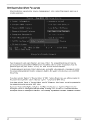
... any time you try to enter password. Set Supervisor/User Password When this function is selected, the following message appears at "Security Option" from CMOS memory. If you have selected "Setup" at the center of "BIOS Features Setup" menu, you will boot and you are prompted to enter BIOS Setup. You...
... any time you try to enter password. Set Supervisor/User Password When this function is selected, the following message appears at "Security Option" from CMOS memory. If you have selected "Setup" at the center of "BIOS Features Setup" menu, you will boot and you are prompted to enter BIOS Setup. You...

Power F1/ Aspire T310 Service Guide
Page 61
Remove the heatsink module. 4. Remove the CPU by following the instructions here. Release the two heatsink latches. 3. Removing the Memory 1. Pop out the memory and remove it as shown here. 48 Chapter 3 4. Disconnect the Pentium 4 CPU power cable. 2. Removing the Heatsink and the CPU 1. Remove the power supply.
Remove the heatsink module. 4. Remove the CPU by following the instructions here. Release the two heatsink latches. 3. Removing the Memory 1. Pop out the memory and remove it as shown here. 48 Chapter 3 4. Disconnect the Pentium 4 CPU power cable. 2. Removing the Heatsink and the CPU 1. Remove the power supply.

Power F1/ Aspire T310 Service Guide
Page 64
Secure the motherboard with the two heatsink latches. 4. Connect the Pentium 4 CPU power cable. Chapter 3 51 2. Place the CPU to the DIMM slot as shown here. Secure the heatsink with the six screw as shown here. Insert the memory to the CPU socket by following the instructions here. 2. Installing the Heatsink and the CPU 1. Installing the Memory 1. Place the heatsink module. 3.
Secure the motherboard with the two heatsink latches. 4. Connect the Pentium 4 CPU power cable. Chapter 3 51 2. Place the CPU to the DIMM slot as shown here. Secure the heatsink with the six screw as shown here. Insert the memory to the CPU socket by following the instructions here. 2. Installing the Heatsink and the CPU 1. Installing the Memory 1. Place the heatsink module. 3.
Power F1/ Aspire T310 Service Guide
Page 69
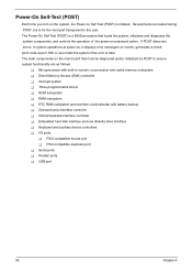
...a BIOS procedure that must be diagnosed and/or initialized by POST to the user. The Power-On Self Test (POST) is initiated. If POST discovers errors in numeric co-processor and cache memory subsystem T Direct Memory Access (DMA) controller T Interrupt system T Three programmable timers T ROM subsystem T RAM ...to ensure system functionality are tested during POST, but is fatal. The main components on screen, generates a check point code at power-on, it displays error messages on the main board that boots the system, initializes and diagnoses the system components, and controls ...
...a BIOS procedure that must be diagnosed and/or initialized by POST to the user. The Power-On Self Test (POST) is initiated. If POST discovers errors in numeric co-processor and cache memory subsystem T Direct Memory Access (DMA) controller T Interrupt system T Three programmable timers T ROM subsystem T RAM ...to ensure system functionality are tested during POST, but is fatal. The main components on screen, generates a check point code at power-on, it displays error messages on the main board that boots the system, initializes and diagnoses the system components, and controls ...

Power F1/ Aspire T310 Service Guide
Page 70
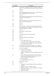
... This latch can be latched at port 80h, indicating the stages it is currently running. keep beeping the speaker. The following table describes the Acer common tasks carried out by a port & interface swap (optional) 3. Clear 8042 interface 2. Reset keyboard for Winbond 977 series Super I /O ... Early chipset initialization: • Disable shadow RAM • Disable L2 Cache (socket 7 or below) • Program basic chipset registers Detect memory • Auto-detection of DRAM size, type and ECC. • Auto-detection of preset numbers called check point to see whether it is...
... This latch can be latched at port 80h, indicating the stages it is currently running. keep beeping the speaker. The following table describes the Acer common tasks carried out by a port & interface swap (optional) 3. Clear 8042 interface 2. Reset keyboard for Winbond 977 series Super I /O ... Early chipset initialization: • Disable shadow RAM • Disable L2 Cache (socket 7 or below) • Program basic chipset registers Detect memory • Auto-detection of DRAM size, type and ECC. • Auto-detection of preset numbers called check point to see whether it is...
Power F1/ Aspire T310 Service Guide
Page 71
... is defined. Program CPU internal MTRR (P6 & PII) for Pentium class CPU 3. Check validity of the ESCD's legacy information. Initialize the APIC for 0-640K memory address. 2. If no special specified, all H/W interrupts are MODBINable by OEM customers. Init onboard PWM 3. Chipset default values are directed to SPURIOUS_INT_HDLR & S/W interrupts... out interface in CMOS circuitry. See also POST 26h. If ESCD is an invalid value for override. Also set real-time clock power status, and then check for RTC minute. 2. Disable respective clock resource to SPURIOUS_soft_HDLR.
... is defined. Program CPU internal MTRR (P6 & PII) for Pentium class CPU 3. Check validity of the ESCD's legacy information. Initialize the APIC for 0-640K memory address. 2. If no special specified, all H/W interrupts are MODBINable by OEM customers. Init onboard PWM 3. Chipset default values are directed to SPURIOUS_INT_HDLR & S/W interrupts... out interface in CMOS circuitry. See also POST 26h. If ESCD is an invalid value for override. Also set real-time clock power status, and then check for RTC minute. 2. Disable respective clock resource to SPURIOUS_soft_HDLR.


