
Power F1/ Aspire T310 Service Guide
Page 12
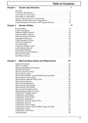
Table of Contents Chapter 1 System Specifications 1 Overview 1 Features & Specification 2 Acer Power F1 Front Panel 4 Acer Power F1 Rear Panel 5 Aspire T310/Acer Power F1 Front Panel 6 Hardware Specifications and Configurations 8 Power Management Function (ACPI support function 16 Chapter 2 System Utilities 17 Entering Setup 18 ... Daughter Board 50 Installing the LED Module 50 Installing the Power Button 50 Installing the Mainboard 50 Installing the Heatsink and the CPU 51 Installing the Memory 51 Installing the Power Supply 52 Installing the Modem card,CD-ROM, Floppy and...
Table of Contents Chapter 1 System Specifications 1 Overview 1 Features & Specification 2 Acer Power F1 Front Panel 4 Acer Power F1 Rear Panel 5 Aspire T310/Acer Power F1 Front Panel 6 Hardware Specifications and Configurations 8 Power Management Function (ACPI support function 16 Chapter 2 System Utilities 17 Entering Setup 18 ... Daughter Board 50 Installing the LED Module 50 Installing the Power Button 50 Installing the Mainboard 50 Installing the Heatsink and the CPU 51 Installing the Memory 51 Installing the Power Supply 52 Installing the Modem card,CD-ROM, Floppy and...

Power F1/ Aspire T310 Service Guide
Page 15
..., 128Mb, 256Mb, 512 Mb and 1Gb technologies. Chipset T SiS 661FX, SiS964L Memory T Socket Type: DDR-SDRAM PC2700/PC2100/PC3200(DDR400) 184-pin socket. Features & Specifications CPU T T T T Support Intel P4 Northwood (Socket 478) processor. Support 800MHz, 533MHz or 400MHz FSB.
..., 128Mb, 256Mb, 512 Mb and 1Gb technologies. Chipset T SiS 661FX, SiS964L Memory T Socket Type: DDR-SDRAM PC2700/PC2100/PC3200(DDR400) 184-pin socket. Features & Specifications CPU T T T T Support Intel P4 Northwood (Socket 478) processor. Support 800MHz, 533MHz or 400MHz FSB.
Power F1/ Aspire T310 Service Guide
Page 19
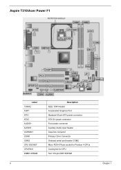
Aspire T310/Acer Power F1 Label 1394A2 AGP1 ATX1 ATX2 AUDIO1 AUXIN1 CASFAN1 CDIN1 COM2 CPU SOCKET CPUFAN1 DIMM1-DIMM2 Description IEEE 1394 Header Accelerated Graphics Port Standard 20-pin ATX power connector ATX12V power connector Front audio connector Auxiliary Audio input header Case fan connector Primary CD-in Connector Onboard serial port header COM2 Micro PGA 478-pin socket for Pentium 4 CPUs Cooling fan for CPU Two 184-pin DDR SDRAM 6 Chapter 1
Aspire T310/Acer Power F1 Label 1394A2 AGP1 ATX1 ATX2 AUDIO1 AUXIN1 CASFAN1 CDIN1 COM2 CPU SOCKET CPUFAN1 DIMM1-DIMM2 Description IEEE 1394 Header Accelerated Graphics Port Standard 20-pin ATX power connector ATX12V power connector Front audio connector Auxiliary Audio input header Case fan connector Primary CD-in Connector Onboard serial port header COM2 Micro PGA 478-pin socket for Pentium 4 CPUs Cooling fan for CPU Two 184-pin DDR SDRAM 6 Chapter 1
Power F1/ Aspire T310 Service Guide
Page 21
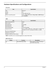
... Setup Utility. 8 Chapter 1 Hardware Specifications and Configurations Processor Item Type Socket Speed Minimum operating speed Specification Pentium 4 478 1.8G~3.06G and 3.2G 0 MHz (If Stop CPU Clock in Sleep State in BIOS Setup is booting to BIOS boot block feature Specification Award v6.0 Flash ROM 4MB 32-pin DIP package PCI...
... Setup Utility. 8 Chapter 1 Hardware Specifications and Configurations Processor Item Type Socket Speed Minimum operating speed Specification Pentium 4 478 1.8G~3.06G and 3.2G 0 MHz (If Stop CPU Clock in Sleep State in BIOS Setup is booting to BIOS boot block feature Specification Award v6.0 Flash ROM 4MB 32-pin DIP package PCI...
Power F1/ Aspire T310 Service Guide
Page 29
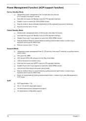
T Resume recovery time: 7-10 sec. T CPU goes into power saving mode. T LED on the panel turns amber colour. T Ultra ... by pushing external switch button, modem ring in and USB keyboard for APM mode. T On board device power management support. T Disable V-sync to control the VESA DPMS monitor. T Hard disk drive goes into SLEEP mode...into Standby mode (for ATA standard interface). T On board device configuration support. 16 Chapter 1 Global Standby Mode T Global power management timer (2-120 minutes, time step=10 minute). T Return to control the VESA DPMS monitor. T S0, S1, ...
T Resume recovery time: 7-10 sec. T CPU goes into power saving mode. T LED on the panel turns amber colour. T Ultra ... by pushing external switch button, modem ring in and USB keyboard for APM mode. T On board device power management support. T Disable V-sync to control the VESA DPMS monitor. T Hard disk drive goes into SLEEP mode...into Standby mode (for ATA standard interface). T On board device configuration support. 16 Chapter 1 Global Standby Mode T Global power management timer (2-120 minutes, time step=10 minute). T Return to control the VESA DPMS monitor. T S0, S1, ...

Power F1/ Aspire T310 Service Guide
Page 36
... following table describes the parameters found in boldface are normally checked. This parameter allows you to improve performance. Parameter CPU Feature Hard Disk Boot Priority CPU L1 & L2 Cache Hyper-Threading Technology Quick Power On Self Test First / Second / Third Boot Device Boot Other Device Description Options The items allow you to load...
... following table describes the parameters found in boldface are normally checked. This parameter allows you to improve performance. Parameter CPU Feature Hard Disk Boot Priority CPU L1 & L2 Cache Hyper-Threading Technology Quick Power On Self Test First / Second / Third Boot Device Boot Other Device Description Options The items allow you to load...

Power F1/ Aspire T310 Service Guide
Page 39
...Support. Techniques such as the RAM Access (data read or write and starting another from the same (non-page mode) DRAM. Parameter Current CPU Frequency / Current DRAM Frequency Performance Mode DRAM Timing Control DRAM CAS Latency RAS Active Time(tRAS) RAS Precharge Time(tRP) RAS to a ... each parameter under the Advanced Chipset Features are the deafult and suggested values. Do not change specifications of the installed DRAM or the installed CPU. Some chipsets require this field unless you to set at the factory depending on the DRAM installed. Auto, 1x, 2x, 4x ,8x...
...Support. Techniques such as the RAM Access (data read or write and starting another from the same (non-page mode) DRAM. Parameter Current CPU Frequency / Current DRAM Frequency Performance Mode DRAM Timing Control DRAM CAS Latency RAS Active Time(tRAS) RAS Precharge Time(tRP) RAS to a ... each parameter under the Advanced Chipset Features are the deafult and suggested values. Do not change specifications of the installed DRAM or the installed CPU. Some chipsets require this field unless you to set at the factory depending on the DRAM installed. Auto, 1x, 2x, 4x ,8x...

Power F1/ Aspire T310 Service Guide
Page 44
..., 8 Min, 12 Min, 20 Min, 30 Min, 40 Min, 1Hour Chapter 2 31 The information stored in which power is s power-down state in memory will be suspended if no system context (CPU or chipset) is lost and hardware maintains all system context is saved to main memory. S1(POS): The S1... devices and all system context. S3 S1 S1&S3 The CPU clock will be stopped and the video signal will return when a Power Management event is a low power state. Full power function will be adopted. Power Management Setup The Power Management menu lets you configure your system to most effectively save...
..., 8 Min, 12 Min, 20 Min, 30 Min, 40 Min, 1Hour Chapter 2 31 The information stored in which power is s power-down state in memory will be suspended if no system context (CPU or chipset) is lost and hardware maintains all system context is saved to main memory. S1(POS): The S1... devices and all system context. S3 S1 S1&S3 The CPU clock will be stopped and the video signal will return when a Power Management event is a low power state. Full power function will be adopted. Power Management Setup The Power Management menu lets you configure your system to most effectively save...

Power F1/ Aspire T310 Service Guide
Page 45
...computer will shut down . Suspend --> Off: During suspend mode, the monitorwill shut down . Susp, Stby --> During suspend or standby mode, the monitor will be powered down . All Modes --> Off: The monitor is pressed for the length of selected IRQ always awakens the system. 3, 4, 5, 7, 9, 10, 11, AUTO... This option allows you to set the delay time before the CPU enters auto thermal mode. Off On Former-Sts Enables you press the power button, the computer enters the suspend/ sleep mode, but if the button is turned off button. Delay 4 Sec...
...computer will shut down . Suspend --> Off: During suspend mode, the monitorwill shut down . Susp, Stby --> During suspend or standby mode, the monitor will be powered down . All Modes --> Off: The monitor is pressed for the length of selected IRQ always awakens the system. 3, 4, 5, 7, 9, 10, 11, AUTO... This option allows you to set the delay time before the CPU enters auto thermal mode. Off On Former-Sts Enables you press the power button, the computer enters the suspend/ sleep mode, but if the button is turned off button. Delay 4 Sec...
Power F1/ Aspire T310 Service Guide
Page 48
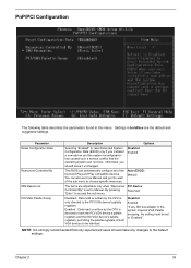
... must be identical. Disabled Enabled This BIOS can automatically configure all of the sub menu to Manual. Data read or written by the CPU is directed to both the PCI VGA device's palette registers and the ISA VGA device's palette registers, permitting the palette registers of both... VGA devices to the PCI VGA device's palette registers. Data read or written by the CPU is only directed to be set to choose specific resources. Otherwise, you installed a new add-on and the system reconfiguration has caused such ...
... must be identical. Disabled Enabled This BIOS can automatically configure all of the sub menu to Manual. Data read or written by the CPU is directed to both the PCI VGA device's palette registers and the ISA VGA device's palette registers, permitting the palette registers of both... VGA devices to the PCI VGA device's palette registers. Data read or written by the CPU is only directed to be set to choose specific resources. Otherwise, you installed a new add-on and the system reconfiguration has caused such ...

Power F1/ Aspire T310 Service Guide
Page 49
Options 36 Chapter 2 These items display the current status of all of the mainboard hardware devices/components such as CPU voltages, temperatures and all fans' speeds. When the processor reaches the temperature you set, the ACPI-aware system will be shut down. PC Health Status The following table describes the parameters found in this menu: Parameter Shutdown Temperature System Component Characteristics Description This option is for setting the shutdown temperature level for the processor.
Options 36 Chapter 2 These items display the current status of all of the mainboard hardware devices/components such as CPU voltages, temperatures and all fans' speeds. When the processor reaches the temperature you set, the ACPI-aware system will be shut down. PC Health Status The following table describes the parameters found in this menu: Parameter Shutdown Temperature System Component Characteristics Description This option is for setting the shutdown temperature level for the processor.
Power F1/ Aspire T310 Service Guide
Page 50
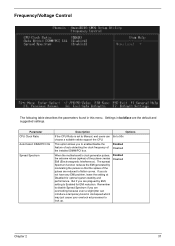
... Enabled for optimal system stability and performance. The spread Spectrum function reduces the EMI generated by EMI, setting to 50x choose a suitable ratioto support the CPU. But if you do not have any EMI problem, leave the setting at Disabled for EMI reduction. Parameter...
... Enabled for optimal system stability and performance. The spread Spectrum function reduces the EMI generated by EMI, setting to 50x choose a suitable ratioto support the CPU. But if you do not have any EMI problem, leave the setting at Disabled for EMI reduction. Parameter...

Power F1/ Aspire T310 Service Guide
Page 52
... instability if you install defaults for a specific option, select and display that may be greater than the performance level of the components, such as the CPU and the memory. If you only want to install setup defaults for all appropriate items in the Setup Utility. Chapter 2 39 Press and then to...
... instability if you install defaults for a specific option, select and display that may be greater than the performance level of the components, such as the CPU and the memory. If you only want to install setup defaults for all appropriate items in the Setup Utility. Chapter 2 39 Press and then to...

Power F1/ Aspire T310 Service Guide
Page 61
4. Removing the Heatsink and the CPU 1. Release the two heatsink latches. 3. Remove the heatsink module. 4. Pop out the memory and remove it as shown here. 48 Chapter 3 Remove the power supply. Disconnect the Pentium 4 CPU power cable. 2. Remove the CPU by following the instructions here. Removing the Memory 1.
4. Removing the Heatsink and the CPU 1. Release the two heatsink latches. 3. Remove the heatsink module. 4. Pop out the memory and remove it as shown here. 48 Chapter 3 Remove the power supply. Disconnect the Pentium 4 CPU power cable. 2. Remove the CPU by following the instructions here. Removing the Memory 1.

Power F1/ Aspire T310 Service Guide
Page 64
Place the heatsink module. 3. Insert the memory to the CPU socket by following the instructions here. 2. Chapter 3 51 Installing the Memory 1. 2. Connect the Pentium 4 CPU power cable. Secure the motherboard with the two heatsink latches. 4. Secure the heatsink with the six screw as shown here. Place the CPU to the DIMM slot as shown here. Installing the Heatsink and the CPU 1.
Place the heatsink module. 3. Insert the memory to the CPU socket by following the instructions here. 2. Chapter 3 51 Installing the Memory 1. 2. Connect the Pentium 4 CPU power cable. Secure the motherboard with the two heatsink latches. 4. Secure the heatsink with the six screw as shown here. Place the CPU to the DIMM slot as shown here. Installing the Heatsink and the CPU 1.
Power F1/ Aspire T310 Service Guide
Page 71
... Early PCI Initialization: • Enumerate PCI bus number • Assign memory & I/O resource • Search for 0-640K memory address. 2. Measure CPU speed. 58 Chapter 4 a value of RTC value: e.g. Init onboard PWM 3. Program early chipset according to check out interface in CMOS circuitry. ... invalid value for PCI & PnP use default value instead. See also POST 26h. Also set real-time clock power status, and then check for Pentium class CPU 3. Load CMOS settings into chipset. Prepare BIOS resource map for RTC minute. 2. Chipset default values are directed...
... Early PCI Initialization: • Enumerate PCI bus number • Assign memory & I/O resource • Search for 0-640K memory address. 2. Measure CPU speed. 58 Chapter 4 a value of RTC value: e.g. Init onboard PWM 3. Program early chipset according to check out interface in CMOS circuitry. ... invalid value for PCI & PnP use default value instead. See also POST 26h. Also set real-time clock power status, and then check for Pentium class CPU 3. Load CMOS settings into chipset. Prepare BIOS resource map for RTC minute. 2. Chipset default values are directed...

Power F1/ Aspire T310 Service Guide
Page 72
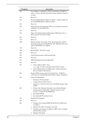
... Test DMA page registers Reserved Reserved Test 8254 Reserved Test 8259 interrupt mask bits for channel 1 Reserved Test 8259 interrupt mask bits for AMD K5 CPU. Put information on screen display, including Award title...
... Test DMA page registers Reserved Reserved Test 8254 Reserved Test 8259 interrupt mask bits for channel 1 Reserved Test 8259 interrupt mask bits for AMD K5 CPU. Put information on screen display, including Award title...

Power F1/ Aspire T310 Service Guide
Page 73
...60 Chapter 4 Assign CSN to items described in case the cacheable ranges between each CPU are not identical. Reserved Initialize PS/2 Mouse Reserved Prepare memory size information for P6 class CPU & program CPU with proper cacheable range. 3. Display PnP logo 2. Initialize Init_Onboard_Super_IO 2. i.e. Initialize L2... to every ISA PnP device Reserved Initialize the combined Trend Anti-Virus code Reserved (Optional Feature) Show message for P6 class CPU. 4. not until this POST stage can users enter the CMOS setup utility. Reserved Initialize USB Keyboard & Mouse Reserved Test ...
...60 Chapter 4 Assign CSN to items described in case the cacheable ranges between each CPU are not identical. Reserved Initialize PS/2 Mouse Reserved Prepare memory size information for P6 class CPU & program CPU with proper cacheable range. 3. Display PnP logo 2. Initialize Init_Onboard_Super_IO 2. i.e. Initialize L2... to every ISA PnP device Reserved Initialize the combined Trend Anti-Virus code Reserved (Optional Feature) Show message for P6 class CPU. 4. not until this POST stage can users enter the CMOS setup utility. Reserved Initialize USB Keyboard & Mouse Reserved Test ...

Power F1/ Aspire T310 Service Guide
Page 76
... to disable parity check. 2. Enter BIOS Setup and load the default settings. 2. System board. 1. BIOS Messages I/O Parity Error CPU Clock Mismatch Real Time Clock Error CMOS Battery Bad CMOS Checksum Error Equipment Configuration Error System Management Memory Bad Memory Error at MMMM:SSSS... Locked Onboard xxx... System Board. 1. Enter BIOS Setup and load the default settings. 3. System board 1. PS/2 keyboard 4. Remove all power supply voltages, switch, and jumper settings before you replace the main board. Conflict(s) Floppy Disk Controller Error Floppy Drive A Error Floppy Drive ...
... to disable parity check. 2. Enter BIOS Setup and load the default settings. 2. System board. 1. BIOS Messages I/O Parity Error CPU Clock Mismatch Real Time Clock Error CMOS Battery Bad CMOS Checksum Error Equipment Configuration Error System Management Memory Bad Memory Error at MMMM:SSSS... Locked Onboard xxx... System Board. 1. Enter BIOS Setup and load the default settings. 3. System board 1. PS/2 keyboard 4. Remove all power supply voltages, switch, and jumper settings before you replace the main board. Conflict(s) Floppy Disk Controller Error Floppy Drive A Error Floppy Drive ...

Power F1/ Aspire T310 Service Guide
Page 86
... into a case, you can begin connecting the mainboard components. Connect the Northbridge cooling fna to the PANEL1. 5. Connect the standard power supply connector to the following: Description 1. Connector ATX1: ATX 20-pin Power Connector Pin 1 2 3 4 5 6 7 8 9 10 Signal Name +3.3V +3.3V Ground +5V Ground +5V Ground PWRGD... 12 13 14 15 16 17 18 19 20 Signal Name +3.3V -12V Ground PS NO# Ground Ground Ground +5V +5V +5V ATX2: ATX12V Power Connector Pin 1 2 3 4 +12V +12V Ground Ground Signal Name Chapter 5 73 Refer to ATX1. 6. Connect the case cooling fan connector to ...
... into a case, you can begin connecting the mainboard components. Connect the Northbridge cooling fna to the PANEL1. 5. Connect the standard power supply connector to the following: Description 1. Connector ATX1: ATX 20-pin Power Connector Pin 1 2 3 4 5 6 7 8 9 10 Signal Name +3.3V +3.3V Ground +5V Ground +5V Ground PWRGD... 12 13 14 15 16 17 18 19 20 Signal Name +3.3V -12V Ground PS NO# Ground Ground Ground +5V +5V +5V ATX2: ATX12V Power Connector Pin 1 2 3 4 +12V +12V Ground Ground Signal Name Chapter 5 73 Refer to ATX1. 6. Connect the case cooling fan connector to ...

