

Power F1/ Aspire T310 Service Guide
Page 3
Revision History Please refer to the table below for the updates made on AcerPower F1/Aspire T310 service guide. 2003/10/29 Date 2003/12/18 Chapter 1 Chapter Chapter 1 Updates > Amend the FSB speed up to 800MHz on page 2 > Memory portion > Memory combination portion >Amend the Rear Panel and mainboard layout without SATA II
Revision History Please refer to the table below for the updates made on AcerPower F1/Aspire T310 service guide. 2003/10/29 Date 2003/12/18 Chapter 1 Chapter Chapter 1 Updates > Amend the FSB speed up to 800MHz on page 2 > Memory portion > Memory combination portion >Amend the Rear Panel and mainboard layout without SATA II

Power F1/ Aspire T310 Service Guide
Page 6
... PARTS, that you with all technical information relating to order FRU parts for Acer's "global" product offering. add-on your Acer office may have decided to -date information available on card, modem, or extra memory capability). If, for whatever reason, a part number change is made, it... supports, please read the following general information. 1. In such cases, please contact your regional Acer office to the BASIC CONFIGURATION decided for repair and ...
... PARTS, that you with all technical information relating to order FRU parts for Acer's "global" product offering. add-on your Acer office may have decided to -date information available on card, modem, or extra memory capability). If, for whatever reason, a part number change is made, it... supports, please read the following general information. 1. In such cases, please contact your regional Acer office to the BASIC CONFIGURATION decided for repair and ...
Power F1/ Aspire T310 Service Guide
Page 10
... to provide you with further technical details. 2. To better fit local market requirements and enhance product competitiveness, your Acer office may have decided to -date information available on card, modem, or extra memory capability). This Service Guide provides you with all technical information relating to those given in this information and the...
... to provide you with further technical details. 2. To better fit local market requirements and enhance product competitiveness, your Acer office may have decided to -date information available on card, modem, or extra memory capability). This Service Guide provides you with all technical information relating to those given in this information and the...
Power F1/ Aspire T310 Service Guide
Page 12
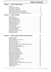
Table of Contents Chapter 1 System Specifications 1 Overview 1 Features & Specification 2 Acer Power F1 Front Panel 4 Acer Power F1 Rear Panel 5 Aspire T310/Acer Power F1 Front Panel 6 Hardware Specifications and Configurations 8 Power Management Function (ACPI support function 16 Chapter 2 System Utilities 17 Entering Setup 18 ... Daughter Board 50 Installing the LED Module 50 Installing the Power Button 50 Installing the Mainboard 50 Installing the Heatsink and the CPU 51 Installing the Memory 51 Installing the Power Supply 52 Installing the Modem card,CD-ROM, Floppy and...
Table of Contents Chapter 1 System Specifications 1 Overview 1 Features & Specification 2 Acer Power F1 Front Panel 4 Acer Power F1 Rear Panel 5 Aspire T310/Acer Power F1 Front Panel 6 Hardware Specifications and Configurations 8 Power Management Function (ACPI support function 16 Chapter 2 System Utilities 17 Entering Setup 18 ... Daughter Board 50 Installing the LED Module 50 Installing the Power Button 50 Installing the Mainboard 50 Installing the Heatsink and the CPU 51 Installing the Memory 51 Installing the Power Supply 52 Installing the Modem card,CD-ROM, Floppy and...

Power F1/ Aspire T310 Service Guide
Page 15
Chipset T SiS 661FX, SiS964L Memory T Socket Type: DDR-SDRAM PC2700/PC2100/PC3200(DDR400) 184-pin socket. T Total: 64MB ~ 2GB (please refer to 3.06GHz+ P4 processor. Support Intel Hyper Threading Technology. ...
Chipset T SiS 661FX, SiS964L Memory T Socket Type: DDR-SDRAM PC2700/PC2100/PC3200(DDR400) 184-pin socket. T Total: 64MB ~ 2GB (please refer to 3.06GHz+ P4 processor. Support Intel Hyper Threading Technology. ...

Power F1/ Aspire T310 Service Guide
Page 22
... (4 banks) 64MB / 128MB / 256MB/ 512MB/1G 1G x2 DDR SDRAM DDR400/333/266 2.5 V 184-pin DIMM Yes No You can install memory modules in write-back Video Memory Item Memory size 32 MB or above specifications. Memory Combinations Slot 1 Slot 2 Slot Memory Module 64, 128, 256, 512MB, 1G 64, 128, 256, 512MB, 1G Maximum System...
... (4 banks) 64MB / 128MB / 256MB/ 512MB/1G 1G x2 DDR SDRAM DDR400/333/266 2.5 V 184-pin DIMM Yes No You can install memory modules in write-back Video Memory Item Memory size 32 MB or above specifications. Memory Combinations Slot 1 Slot 2 Slot Memory Module 64, 128, 256, 512MB, 1G 64, 128, 256, 512MB, 1G Maximum System...
Power F1/ Aspire T310 Service Guide
Page 30
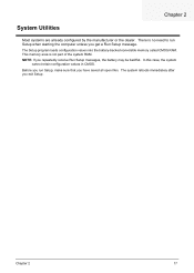
... immediately after you repeatedly receive Run Setup messages, the battery may be bad/flat. The Setup program loads configuration values into the battery-backed nonvolatile memory called CMOS RAM. NOTE: If you exit Setup. In this case, the system cannot retain configuration values in CMOS. Chapter 2 17 Before you run Setup...
... immediately after you repeatedly receive Run Setup messages, the battery may be bad/flat. The Setup program loads configuration values into the battery-backed nonvolatile memory called CMOS RAM. NOTE: If you exit Setup. In this case, the system cannot retain configuration values in CMOS. Chapter 2 17 Before you run Setup...

Power F1/ Aspire T310 Service Guide
Page 34
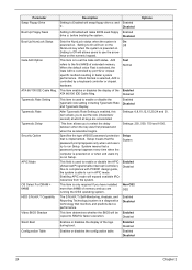
... IDE Channel 1 Master IDE Channel 1 Slave Drive A Drive B Floppy 3 Mode Support Video Halt On Base Memory Extended Memory Total Memory Description Options Allows you to control the system stops in case of Power On Self Test errors (POST). The IDE CD-ROM is VGA/EGA. Disabled, Enabled This item specifies the... type of video card in use VGA only, this function is reserved for system use extended memory. Everything above and beyond the standard...
... IDE Channel 1 Master IDE Channel 1 Slave Drive A Drive B Floppy 3 Mode Support Video Halt On Base Memory Extended Memory Total Memory Description Options Allows you to control the system stops in case of Power On Self Test errors (POST). The IDE CD-ROM is VGA/EGA. Disabled, Enabled This item specifies the... type of video card in use VGA only, this function is reserved for system use extended memory. Everything above and beyond the standard...

Power F1/ Aspire T310 Service Guide
Page 36
...table describes the parameters found in boldface are normally checked. Press [Enter] Uses internal level 1 (L1) and external level 2 (L2) cache memory to specify the system Enabled boot up POST by skipping some items that are the default and suggested settings. Floppy, LS120, HDD-0, SCSI, CDROM... HDD-3, ZIP, LAN, Disabled (Disable this menu. Parameter CPU Feature Hard Disk Boot Priority CPU L1 & L2 Cache Hyper-Threading Technology Quick Power On Self Test First / Second / Third Boot Device Boot Other Device Description Options The items allow you to load the disk operating system. ...
...table describes the parameters found in boldface are normally checked. Press [Enter] Uses internal level 1 (L1) and external level 2 (L2) cache memory to specify the system Enabled boot up POST by skipping some items that are the default and suggested settings. Floppy, LS120, HDD-0, SCSI, CDROM... HDD-3, ZIP, LAN, Disabled (Disable this menu. Parameter CPU Feature Hard Disk Boot Priority CPU L1 & L2 Cache Hyper-Threading Technology Quick Power On Self Test First / Second / Third Boot Device Boot Other Device Description Options The items allow you to load the disk operating system. ...
Power F1/ Aspire T310 Service Guide
Page 37
... including Typematic Rate Disabled and Typematic Deplay. When Normal is selected, A20 is implemented. Security Option Specifies the type of extended memory. Setting to Off will allows users to the first 64KB of BIOS password protection that the password prompt appears only when end ...20,24 and 30. Enabled Disabled 24 Chapter 2 Fast Normal ATA 66/100 IDE Cable Msg. Disbaled Typematic Rate Setting This item is powered on . System means that monitors and predicts device performance. Setup System APIC Mode This field is a diagnostics technology that a password prompt...
... including Typematic Rate Disabled and Typematic Deplay. When Normal is selected, A20 is implemented. Security Option Specifies the type of extended memory. Setting to Off will allows users to the first 64KB of BIOS password protection that the password prompt appears only when end ...20,24 and 30. Enabled Disabled 24 Chapter 2 Fast Normal ATA 66/100 IDE Cable Msg. Disbaled Typematic Rate Setting This item is powered on . System means that monitors and predicts device performance. Setup System APIC Mode This field is a diagnostics technology that a password prompt...

Power F1/ Aspire T310 Service Guide
Page 39
... base address is performed after receiving it. Settings in HCLKs of 2, 2.5, or 3. The RAS Precharge value is typically about the same as memory interleaving, or use of time a CAS is valid or not. The lower the better, but some DRAM does not support low figures. 2T... By SPD Manual This item controls the timing delay (in boldface are presented below. Some chipsets require this field unless you to graphics memory address space. Parameter Current CPU Frequency / Current DRAM Frequency Performance Mode DRAM Timing Control DRAM CAS Latency RAS Active Time(tRAS) RAS ...
... base address is performed after receiving it. Settings in HCLKs of 2, 2.5, or 3. The RAS Precharge value is typically about the same as memory interleaving, or use of time a CAS is valid or not. The lower the better, but some DRAM does not support low figures. 2T... By SPD Manual This item controls the timing delay (in boldface are presented below. Some chipsets require this field unless you to graphics memory address space. Parameter Current CPU Frequency / Current DRAM Frequency Performance Mode DRAM Timing Control DRAM CAS Latency RAS Active Time(tRAS) RAS ...

Power F1/ Aspire T310 Service Guide
Page 40
OnChip AGP Control Press [Enter] to enter the sub-menu and the following screen appears: Parameter VGA Share Memory Size Description Selects the VGA share memory size Options 16, 32MB, 64MB, 128MB Parameter System BIOS Cacheable Video RAM Cacheable Description Options Enables or disables the system BIOS cacheable. Disabled Enabled Chapter 2 27 Disabled Enabled Enables or disables the video RAM cacheable.
OnChip AGP Control Press [Enter] to enter the sub-menu and the following screen appears: Parameter VGA Share Memory Size Description Selects the VGA share memory size Options 16, 32MB, 64MB, 128MB Parameter System BIOS Cacheable Video RAM Cacheable Description Options Enables or disables the system BIOS cacheable. Disabled Enabled Chapter 2 27 Disabled Enabled Enables or disables the video RAM cacheable.

Power F1/ Aspire T310 Service Guide
Page 44
... Suspend Mode Description Options This item specifies the power saving modes for a specified length of computer use. S3 (STR): The S3 sleep mode is s power-down state in which power is supplied only to essential components such as main memory and wake-capable devices and all system context.... The information stored in memory will return when a Power Management event is lost and hardware maintains all system ...
... Suspend Mode Description Options This item specifies the power saving modes for a specified length of computer use. S3 (STR): The S3 sleep mode is s power-down state in which power is supplied only to essential components such as main memory and wake-capable devices and all system context.... The information stored in memory will return when a Power Management event is lost and hardware maintains all system ...

Power F1/ Aspire T310 Service Guide
Page 52
... install defaults for a specific option, select and display that may be greater than the performance level of the components, such as the CPU and the memory. You can cause fatal errors or instability if you install the optimized defaults when your hardware does not support them.
... install defaults for a specific option, select and display that may be greater than the performance level of the components, such as the CPU and the memory. You can cause fatal errors or instability if you install the optimized defaults when your hardware does not support them.
Power F1/ Aspire T310 Service Guide
Page 53
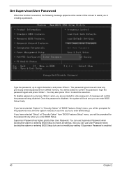
..., the system will boot and you can enter BIOS Setup freely. Once the password is selected, the following message appears at "Security Option" from CMOS memory. Also you in creating a password. Type the password again and press . To disable password, just press when you enter BIOS Setup. Type the password, up...
..., the system will boot and you can enter BIOS Setup freely. Once the password is selected, the following message appears at "Security Option" from CMOS memory. Also you in creating a password. Type the password again and press . To disable password, just press when you enter BIOS Setup. Type the password, up...

Power F1/ Aspire T310 Service Guide
Page 61
Removing the Heatsink and the CPU 1. Remove the CPU by following the instructions here. Release the two heatsink latches. 3. Remove the heatsink module. 4. 4. Disconnect the Pentium 4 CPU power cable. 2. Pop out the memory and remove it as shown here. 48 Chapter 3 Remove the power supply. Removing the Memory 1.
Removing the Heatsink and the CPU 1. Remove the CPU by following the instructions here. Release the two heatsink latches. 3. Remove the heatsink module. 4. 4. Disconnect the Pentium 4 CPU power cable. 2. Pop out the memory and remove it as shown here. 48 Chapter 3 Remove the power supply. Removing the Memory 1.

Power F1/ Aspire T310 Service Guide
Page 64
Secure the motherboard with the two heatsink latches. 4. Place the heatsink module. 3. Installing the Memory 1. Chapter 3 51 Connect the Pentium 4 CPU power cable. Installing the Heatsink and the CPU 1. Place the CPU to the DIMM slot as shown here. 2. Insert the memory to the CPU socket by following the instructions here. 2. Secure the heatsink with the six screw as shown here.
Secure the motherboard with the two heatsink latches. 4. Place the heatsink module. 3. Installing the Memory 1. Chapter 3 51 Connect the Pentium 4 CPU power cable. Installing the Heatsink and the CPU 1. Place the CPU to the DIMM slot as shown here. 2. Insert the memory to the CPU socket by following the instructions here. 2. Secure the heatsink with the six screw as shown here.
Power F1/ Aspire T310 Service Guide
Page 69
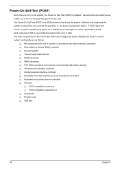
...components on the main board that boots the system, initializes and diagnoses the system components, and controls the operation of the power-on password option. Several items are tested during POST, but is for the most part transparent to ensure system functionality ...are as follows: T Microprocessor with built-in system operations at power-on, it displays error messages on Self Test (POST) is initiated. If POST discovers errors in numeric co-processor and cache memory subsystem T Direct Memory Access (DMA) controller T Interrupt system T Three programmable timers T ROM...
...components on the main board that boots the system, initializes and diagnoses the system components, and controls the operation of the power-on password option. Several items are tested during POST, but is for the most part transparent to ensure system functionality ...are as follows: T Microprocessor with built-in system operations at power-on, it displays error messages on Self Test (POST) is initiated. If POST discovers errors in numeric co-processor and cache memory subsystem T Direct Memory Access (DMA) controller T Interrupt system T Three programmable timers T ROM...

Power F1/ Aspire T310 Service Guide
Page 70
... Early chipset initialization: • Disable shadow RAM • Disable L2 Cache (socket 7 or below) • Program basic chipset registers Detect memory • Auto-detection of DRAM size, type and ECC. • Auto-detection of preset numbers called check point to be read and shown...1. Disable PS/2 mouse interface (optional) 2. Reserved Auto detect flash type to see whether it is currently running. The following table describes the Acer common tasks carried out by a port & interface swap (optional) 3. Reset keyboard for keyboard & mouse followed by POST. Reserved Chapter 4 57...
... Early chipset initialization: • Disable shadow RAM • Disable L2 Cache (socket 7 or below) • Program basic chipset registers Detect memory • Auto-detection of DRAM size, type and ECC. • Auto-detection of preset numbers called check point to be read and shown...1. Disable PS/2 mouse interface (optional) 2. Reserved Auto detect flash type to see whether it is currently running. The following table describes the Acer common tasks carried out by a port & interface swap (optional) 3. Reset keyboard for keyboard & mouse followed by POST. Reserved Chapter 4 57...
Power F1/ Aspire T310 Service Guide
Page 71
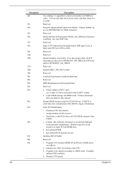
...out interface in CMOS circuitry. If Smos checksum fails, use . Early PCI Initialization: • Enumerate PCI bus number • Assign memory & I/O resource • Search for PCI & PnP use default value instead. See also POST 26h. Reserved Reserved Initial interrupts vector...into chipset. If ESCD is an invalid value for Pentium class CPU 3. Also set real-time clock power status, and then check for 0-640K memory address. 2. Reserved Initial onboard clock generator if Early_Init_Onboard_Generator is not defined Onboard clock generator initialization. Reserved Detect...
...out interface in CMOS circuitry. If Smos checksum fails, use . Early PCI Initialization: • Enumerate PCI bus number • Assign memory & I/O resource • Search for PCI & PnP use default value instead. See also POST 26h. Reserved Reserved Initial interrupts vector...into chipset. If ESCD is an invalid value for Pentium class CPU 3. Also set real-time clock power status, and then check for 0-640K memory address. 2. Reserved Initial onboard clock generator if Early_Init_Onboard_Generator is not defined Onboard clock generator initialization. Reserved Detect...


