
PD100 and PD120 Service Guide
Page 1
for more information, please refer to http://csd.acer.com.tw PRINTED IN TAIWAN PD100 / PD120 Service Guide Service guide files and updates are available on the AIPG/CSD web;
for more information, please refer to http://csd.acer.com.tw PRINTED IN TAIWAN PD100 / PD120 Service Guide Service guide files and updates are available on the AIPG/CSD web;

PD100 and PD120 Service Guide
Page 2
Date Chapter Updates II Revision History Please refer to the table below for the updates made on PD100 / PD120 service guide.
Date Chapter Updates II Revision History Please refer to the table below for the updates made on PD100 / PD120 service guide.

PD100 and PD120 Service Guide
Page 3
... of Intel Corporation. Pentium 4 and Celeron are trademarks and/or registered trademarks of their purchase, the buyer (and not Acer Incorporated, its distributor, or its dealer) assumes the entire cost of Intel Corporation. Disclaimer The information in any form or by... Acer Incorporated. Should the programs prove defective following their respective holders. Acer is a registered trademark of all necessary servicing, repair, and any incidental or consequential damages resulting from ...
... of Intel Corporation. Pentium 4 and Celeron are trademarks and/or registered trademarks of their purchase, the buyer (and not Acer Incorporated, its distributor, or its dealer) assumes the entire cost of Intel Corporation. Disclaimer The information in any form or by... Acer Incorporated. Should the programs prove defective following their respective holders. Acer is a registered trademark of all necessary servicing, repair, and any incidental or consequential damages resulting from ...

PD100 and PD120 Service Guide
Page 4
NOTE WARNING CAUTION IMPORTANT Gives bits and pieces of procedures. Gives precautionary measures to avoid possible hardware or software problems. Reminds you to the current topic. Conventions The following conventions are used in this manual: Screen messages Denotes actual messages that might result from doing or not doing specific actions. IV Alerts you to do specific actions relevant to the accomplishment of additional information related to any damage that appear on screen.
NOTE WARNING CAUTION IMPORTANT Gives bits and pieces of procedures. Gives precautionary measures to avoid possible hardware or software problems. Reminds you to the current topic. Conventions The following conventions are used in this manual: Screen messages Denotes actual messages that might result from doing or not doing specific actions. IV Alerts you to do specific actions relevant to the accomplishment of additional information related to any damage that appear on screen.

PD100 and PD120 Service Guide
Page 5
... that you should check the most up-to-date information available on card, modem, or extra memory capability). If, for Acer's "global" product offering. For ACER-AUTHORIZED SERVICE PROVIDERS, your regional office MAY have a DIFFERENT part number code to the BASIC CONFIGURATION decided for whatever reason, a...product it will NOT be noted in the printed Service Guide. To better fit local market requirements and enhance product competitiveness, your Acer office may have decided to order FRU parts for repair and service of customer machines. In such cases, please contact your ...
... that you should check the most up-to-date information available on card, modem, or extra memory capability). If, for Acer's "global" product offering. For ACER-AUTHORIZED SERVICE PROVIDERS, your regional office MAY have a DIFFERENT part number code to the BASIC CONFIGURATION decided for whatever reason, a...product it will NOT be noted in the printed Service Guide. To better fit local market requirements and enhance product competitiveness, your Acer office may have decided to order FRU parts for repair and service of customer machines. In such cases, please contact your ...
PD100 and PD120 Service Guide
Page 6
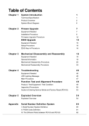
The Different Parts between PD100 and PD120 82 PCBA Code Definition 81 III. Table of Contents Chapter 1 System Introduction 1 Technical Specification 1 Product Overview 2 System Block Diagram 6 Chapter 2 Firware Upgrade 7 Equipment ... Procedure 47 Function Test and Alignment Procedure 49 Product / Test Equipment / Test Condition 49 Inspection Procecdure 50 Guide to Entering Service Mode and Factory Reset (PD100) 53 Chapter 5 Exploded Overview 54 Exploded Overview 54 Appendix Serial Number Definition System 80 I. Serial Number System Definition 80 II.
The Different Parts between PD100 and PD120 82 PCBA Code Definition 81 III. Table of Contents Chapter 1 System Introduction 1 Technical Specification 1 Product Overview 2 System Block Diagram 6 Chapter 2 Firware Upgrade 7 Equipment ... Procedure 47 Function Test and Alignment Procedure 49 Product / Test Equipment / Test Condition 49 Inspection Procecdure 50 Guide to Entering Service Mode and Factory Reset (PD100) 53 Chapter 5 Exploded Overview 54 Exploded Overview 54 Appendix Serial Number Definition System 80 I. Serial Number System Definition 80 II.
PD100 and PD120 Service Guide
Page 7
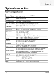
Eco Mode) 1300 ANSI Lumens (Engineering Minimum; Eco Mode without DVD/wireless) 30 dB(A) (Typical, Under 23 +/- 20C; Chapter 1 System Introduction Technical Specification Item Dimensions (WxHxD) Weight Tilt Angle Keystone correction Lamp Door Projection Power Supply Projection Lens Throw Distance Brightness Contrast Uniformity Temperature Maximum Humidity Acoustic noise level Lamp Life Altitude MTBF Description 230 x 122.8 x 238 mm Approx. 4.85 lbs (2.2 Kg) 7 degree with elevator mechanism +/-16 degree (32 degree) (Horizontal) Lamp power supply shut off automatically when door open ...
Eco Mode) 1300 ANSI Lumens (Engineering Minimum; Eco Mode without DVD/wireless) 30 dB(A) (Typical, Under 23 +/- 20C; Chapter 1 System Introduction Technical Specification Item Dimensions (WxHxD) Weight Tilt Angle Keystone correction Lamp Door Projection Power Supply Projection Lens Throw Distance Brightness Contrast Uniformity Temperature Maximum Humidity Acoustic noise level Lamp Life Altitude MTBF Description 230 x 122.8 x 238 mm Approx. 4.85 lbs (2.2 Kg) 7 degree with elevator mechanism +/-16 degree (32 degree) (Horizontal) Lamp power supply shut off automatically when door open ...
PD100 and PD120 Service Guide
Page 9
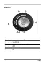
Control Panel Item 1 2 3 4 5 6 7 Description Lamp Indicator LED Temp Indicator LED Power / Standby and Indicator LED (Power LED) Source Resync Four Directional Select Keys Menu 3 Chapter 1
Control Panel Item 1 2 3 4 5 6 7 Description Lamp Indicator LED Temp Indicator LED Power / Standby and Indicator LED (Power LED) Source Resync Four Directional Select Keys Menu 3 Chapter 1

PD100 and PD120 Service Guide
Page 10
Connection Ports Item 1 2 3 4 5 6 7 8 9 10 Description DVI Input Connector (for Digital signal with HDCP function) (Optional) PC Analog Signal / HDTV / Component Video Input Connector Audio Input Connector S-Video Input Connector Monitor Loop-through Output Connector USB Connector Remote Control IR Receiver Composite Video Input Connector KensingtonTM Lock Port 5V DC Output Jack (dfor attached dongle device) (for PD100 only) (for PD120 only) Chapter 1 4
Connection Ports Item 1 2 3 4 5 6 7 8 9 10 Description DVI Input Connector (for Digital signal with HDCP function) (Optional) PC Analog Signal / HDTV / Component Video Input Connector Audio Input Connector S-Video Input Connector Monitor Loop-through Output Connector USB Connector Remote Control IR Receiver Composite Video Input Connector KensingtonTM Lock Port 5V DC Output Jack (dfor attached dongle device) (for PD100 only) (for PD120 only) Chapter 1 4
PD100 and PD120 Service Guide
Page 11
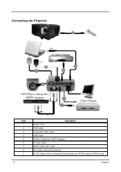
Connecting the Projector Item 1 2 3 4 5 6 7 8 9 5 Description Power Cord VGA Cable Composite Video Cable USB Cable VGA to Component / HDTV Adapter S-Video Cable Audio Cable Jack / Jack DVI Cable (Optional Accessory) 5V DC Output Jack for attached Dongle Device (for PD100 only) (for PD120 only) Chapter 1
Connecting the Projector Item 1 2 3 4 5 6 7 8 9 5 Description Power Cord VGA Cable Composite Video Cable USB Cable VGA to Component / HDTV Adapter S-Video Cable Audio Cable Jack / Jack DVI Cable (Optional Accessory) 5V DC Output Jack for attached Dongle Device (for PD100 only) (for PD120 only) Chapter 1
PD100 and PD120 Service Guide
Page 12
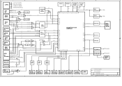
A B C D E LVPS +3.3V/1.3A (1.5A Max) +5.0V/3.2A (3.5A Max) DRCG RDRAM SDRAM (Optioin) FLASH ROM +13.0V/0.4A (1.0A Max) +385V/0.62A (0.65A Max) TMDS IN 1 DVI DVI RS-232 IN 2 DDC I2C / 8 / 2 / DVI EDID DVI HDCP SiI169 / SiI1169 24 / 3 / 2 / PMADR PMDAT 21 / 24 / 16 GPI 16 / PMDAT Expander / 16 Bits 1 2 VGA RGB Out / 2 EDID R/W I2C 2 / OUT HV Out / GPO 16 Expander / 16 Bits 3 2 DDC I2C 2 / / VGA EDID 2 VGA RS-232 / Sync / ALF HV VGA IN VGA RGB VGA HV 3 / VGA RGB 3 DVD YPbPr RGB 3 / 24 / Digital RGB Ctrl & Reset 23 DAD1000 /...
A B C D E LVPS +3.3V/1.3A (1.5A Max) +5.0V/3.2A (3.5A Max) DRCG RDRAM SDRAM (Optioin) FLASH ROM +13.0V/0.4A (1.0A Max) +385V/0.62A (0.65A Max) TMDS IN 1 DVI DVI RS-232 IN 2 DDC I2C / 8 / 2 / DVI EDID DVI HDCP SiI169 / SiI1169 24 / 3 / 2 / PMADR PMDAT 21 / 24 / 16 GPI 16 / PMDAT Expander / 16 Bits 1 2 VGA RGB Out / 2 EDID R/W I2C 2 / OUT HV Out / GPO 16 Expander / 16 Bits 3 2 DDC I2C 2 / / VGA EDID 2 VGA RS-232 / Sync / ALF HV VGA IN VGA RGB VGA HV 3 / VGA RGB 3 DVD YPbPr RGB 3 / 24 / Digital RGB Ctrl & Reset 23 DAD1000 /...
PD100 and PD120 Service Guide
Page 13
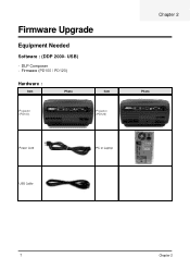
Firmware (PD100 / PD120) Hardware : Item Photo Item Projector (PD100) Projector (PD120) Chapter 2 Photo Power Cord PC or Laptop USB Cable 7 Chapter 2 USB) - Firmware Upgrade Equipment Needed Software : (DDP 2000- DLP Composer -
Firmware (PD100 / PD120) Hardware : Item Photo Item Projector (PD100) Projector (PD120) Chapter 2 Photo Power Cord PC or Laptop USB Cable 7 Chapter 2 USB) - Firmware Upgrade Equipment Needed Software : (DDP 2000- DLP Composer -

PD100 and PD120 Service Guide
Page 14
Click "Next" button. 4 Next Click ""Next"" button. Chapter2 8 Installation Procedure DLP Composer Lite Setup Procedure No Step Procedure 1 Execute FW program Choose "DLP Composer Lite v3.6 Setup" program. 2 Next Click "Next" button. Reading the "License Agreement" rules. 2. Choose "I accept and agree to be bound by all the terms and conditions of this License Agreement" icon, 3. Photo 3 Next 1.
Click "Next" button. 4 Next Click ""Next"" button. Chapter2 8 Installation Procedure DLP Composer Lite Setup Procedure No Step Procedure 1 Execute FW program Choose "DLP Composer Lite v3.6 Setup" program. 2 Next Click "Next" button. Reading the "License Agreement" rules. 2. Choose "I accept and agree to be bound by all the terms and conditions of this License Agreement" icon, 3. Photo 3 Next 1.

PD100 and PD120 Service Guide
Page 15
Choose "All" icon 2. Photo 6 Next Click "Next" button. 7 Processing The program is executing "Initializing" status. 9 Chapter 2 No Step 5 Next Procedure 1. Click "Next" button.
Choose "All" icon 2. Photo 6 Next Click "Next" button. 7 Processing The program is executing "Initializing" status. 9 Chapter 2 No Step 5 Next Procedure 1. Click "Next" button.
PD100 and PD120 Service Guide
Page 16
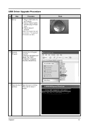
Plug in Power Cord. 3. Hold on "Menu" button and then plug in USB Cable into the Projector. 2. Chapter2 10 The light will not function. continue Then, wait for about 1 minute. USB Driver Upgrade Procedure No Step 1 Set-up Procedure 1. Wait for about 5 seconds. (Note: The system fan will not function as well.) 2 Execute Program Execute the C:\Program files\DLP Composer\usbupdata.cmd. (Note: The "DLP Composer" program must be closed first.) Photo 3 Type any key to Type any key to continue.
Plug in Power Cord. 3. Hold on "Menu" button and then plug in USB Cable into the Projector. 2. Chapter2 10 The light will not function. continue Then, wait for about 1 minute. USB Driver Upgrade Procedure No Step 1 Set-up Procedure 1. Wait for about 5 seconds. (Note: The system fan will not function as well.) 2 Execute Program Execute the C:\Program files\DLP Composer\usbupdata.cmd. (Note: The "DLP Composer" program must be closed first.) Photo 3 Type any key to Type any key to continue.

PD100 and PD120 Service Guide
Page 17
If not, repeart installed Step 1~5. Device Manager 11 Chapter 2 No Step 4 Update Successfully Procedure Click "OK". The USB driver is updated successfully. Right click "My computer" on the popup menu to ensure "DDP2000" & "DDP2000" and "WinDriver" are "Windriver" are properly properly installed. Photo 5 Device Manager 1. Select "Properties" on the desktop. 2. Choose "Hardware" and then click "Device Manager". 6 Ensure Click "Jungo" to launch the "System Properties" window. 3.
If not, repeart installed Step 1~5. Device Manager 11 Chapter 2 No Step 4 Update Successfully Procedure Click "OK". The USB driver is updated successfully. Right click "My computer" on the popup menu to ensure "DDP2000" & "DDP2000" and "WinDriver" are "Windriver" are properly properly installed. Photo 5 Device Manager 1. Select "Properties" on the desktop. 2. Choose "Hardware" and then click "Device Manager". 6 Ensure Click "Jungo" to launch the "System Properties" window. 3.
PD100 and PD120 Service Guide
Page 18
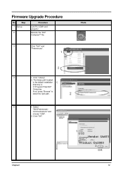
Select "Edit\Preferences\ Communications" and choose "USB". 2. Firmware Upgrade Procedure No Step 1 Set-up 2 Procedure Link PC COM1 and projector Execute the "DLP ComposeTM" file.. 3 Click "Edit" and "Preferences". 1 Photo 2 4 1. If not, press "Browse" to select the right path. 5 1. Chapter2 1 USB Vendor: Ux451 Product: Ox2000 2 OK 12 Click "OK". The library path located in the default installation directory is: C:\Program Files\DLP Composer. Click "Library". 2.
Select "Edit\Preferences\ Communications" and choose "USB". 2. Firmware Upgrade Procedure No Step 1 Set-up 2 Procedure Link PC COM1 and projector Execute the "DLP ComposeTM" file.. 3 Click "Edit" and "Preferences". 1 Photo 2 4 1. If not, press "Browse" to select the right path. 5 1. Chapter2 1 USB Vendor: Ux451 Product: Ox2000 2 OK 12 Click "OK". The library path located in the default installation directory is: C:\Program Files\DLP Composer. Click "Library". 2.
PD100 and PD120 Service Guide
Page 19
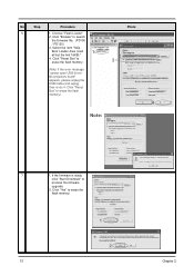
... No projectors found" appears, please unplug the USB Cable and replug, then re-do 4. No Step Procedure 6 1. Click "Reset Bus" to search the firmware file. (PD100 / PD120) 3. Click "Yes" to erase the flash memory. 1 2 13 Chapter 2
... No projectors found" appears, please unplug the USB Cable and replug, then re-do 4. No Step Procedure 6 1. Click "Reset Bus" to search the firmware file. (PD100 / PD120) 3. Click "Yes" to erase the flash memory. 1 2 13 Chapter 2
PD100 and PD120 Service Guide
Page 20
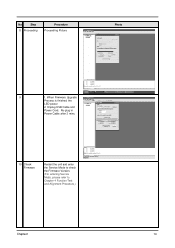
No Step 8 Proceeding Procedure Proceeding Picture Photo 9 1. Re-plug in Power Cable after 3 mins. 10 Check Firmware Restart the unit and enter the Service Mode to check the Firmware Version. (For entering Service Mode, please refer to Chapter 4 Function Test and Alignment Procedure.) Chapter2 14 When Firmware Upgrade Process is finished, the LED power 2. Unplug USB Cable and Power Cord.
No Step 8 Proceeding Procedure Proceeding Picture Photo 9 1. Re-plug in Power Cable after 3 mins. 10 Check Firmware Restart the unit and enter the Service Mode to check the Firmware Version. (For entering Service Mode, please refer to Chapter 4 Function Test and Alignment Procedure.) Chapter2 14 When Firmware Upgrade Process is finished, the LED power 2. Unplug USB Cable and Power Cord.
PD100 and PD120 Service Guide
Page 21
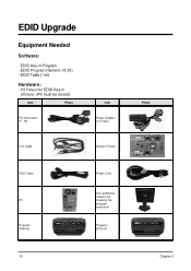
EDID Key-in (Fixture: JP3 must be closed) Item Photo RS-232 Cable (F - M) Item Power Adapter for Fixture DVI Cable Generic Fixture VGA Cable PC Projector (PD100) Power Cord One additional monitor (for EDID Key-in Program - V3 Fixture for checking the program execution) Projector (PD120) 15 Photo Chapter 2 EDID Table (*.ini) Hardware: - EDID Program (Generic V0.51) - EDID Upgrade Equipment Needed Software: -
EDID Key-in (Fixture: JP3 must be closed) Item Photo RS-232 Cable (F - M) Item Power Adapter for Fixture DVI Cable Generic Fixture VGA Cable PC Projector (PD100) Power Cord One additional monitor (for EDID Key-in Program - V3 Fixture for checking the program execution) Projector (PD120) 15 Photo Chapter 2 EDID Table (*.ini) Hardware: - EDID Program (Generic V0.51) - EDID Upgrade Equipment Needed Software: -