Service Guide for Aspire M1640 / M3640 / M5640
Page 6
... Aspire M3640 Rear Panel 12 Aspire M1640 Front Panel 13 Aspire M1640 Rear Panel 14 Hardware Specifications and Configurations 15 Power Management Function (ACPI support function 19 Chapter 2 System Utilities 20 Entering Setup 21 Product Information 23 Standard CMOS Features 24 Advanced BIOS Features 27 Integrated Peripherals 31 Power Management 38 PnP/PCI Configuration 41 PC Health Status 43 Frequency/Voltage Control 44 Load Default Settings 46 Set Supervisor/User Password 47 Save & Exit Setup 49 Exit Without Saving 50 Chapter 3 Machine Disassembly and Replacement...
... Aspire M3640 Rear Panel 12 Aspire M1640 Front Panel 13 Aspire M1640 Rear Panel 14 Hardware Specifications and Configurations 15 Power Management Function (ACPI support function 19 Chapter 2 System Utilities 20 Entering Setup 21 Product Information 23 Standard CMOS Features 24 Advanced BIOS Features 27 Integrated Peripherals 31 Power Management 38 PnP/PCI Configuration 41 PC Health Status 43 Frequency/Voltage Control 44 Load Default Settings 46 Set Supervisor/User Password 47 Save & Exit Setup 49 Exit Without Saving 50 Chapter 3 Machine Disassembly and Replacement...
Service Guide for Aspire M1640 / M3640 / M5640
Page 9
USB Controller Type: NV MCP73PV/S Ports Quantity: 10 4 back panel ports On-board: 3 2*5 headers 4 ports for front daughter board 4 ports for rear I/O 2 ports for internal card reader. Connector Pin: standard Intel FPIO pin definition Data transfer rate support: USB 2.0/1.1 1394 Controller: VIA VT6308P 1394a controller Connector Quantity: 2 3 Rear 6 jack follow HD audio definition, example as below Audio jacks color coding: should meet Microsoft Windows Logo Program Device Requirements: Audio-0002 1 S/PDIF-out header (1*4) 1 AUX-In header (1*4) 1 front panel audio header (2*5) Add HD de-pop...
USB Controller Type: NV MCP73PV/S Ports Quantity: 10 4 back panel ports On-board: 3 2*5 headers 4 ports for front daughter board 4 ports for rear I/O 2 ports for internal card reader. Connector Pin: standard Intel FPIO pin definition Data transfer rate support: USB 2.0/1.1 1394 Controller: VIA VT6308P 1394a controller Connector Quantity: 2 3 Rear 6 jack follow HD audio definition, example as below Audio jacks color coding: should meet Microsoft Windows Logo Program Device Requirements: Audio-0002 1 S/PDIF-out header (1*4) 1 AUX-In header (1*4) 1 front panel audio header (2*5) Add HD de-pop...
Service Guide for Aspire M1640 / M3640 / M5640
Page 10
... Note: Boot ROM should be included (PXE function should be built in with default and RPL function is optional by service BIOS) BIOS shall auto detect FDD to avoid checksum error when boot I/O Connector Controller: Super I /O Connector 1 PS/2 Keyboard port, 1 PS/2 Mouse port, 1 COM port 1 DVI port (Aspire M1000 series only) 1 HDMI port (Aspire M3000/5000 series only), 1 D-Sub port, 1 RJ45 LAN port, 1 IEEE 1394 port (6 pin) (Aspire sku only) 4 USB ports 7.1 channel phone jack (6 audio jacks) On-board connectors 1 CPU socket 2 DDR-2 memory sockets 1 PCI Express x16 slot 4
... Note: Boot ROM should be included (PXE function should be built in with default and RPL function is optional by service BIOS) BIOS shall auto detect FDD to avoid checksum error when boot I/O Connector Controller: Super I /O Connector 1 PS/2 Keyboard port, 1 PS/2 Mouse port, 1 COM port 1 DVI port (Aspire M1000 series only) 1 HDMI port (Aspire M3000/5000 series only), 1 D-Sub port, 1 RJ45 LAN port, 1 IEEE 1394 port (6 pin) (Aspire sku only) 4 USB ports 7.1 channel phone jack (6 audio jacks) On-board connectors 1 CPU socket 2 DDR-2 memory sockets 1 PCI Express x16 slot 4
Service Guide for Aspire M1640 / M3640 / M5640
Page 11
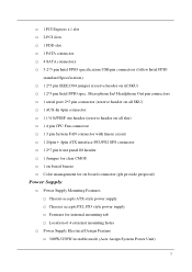
1 PCI Express x 1 slot 2 PCI slots 1 FDD slot 1 PATA connector 4 SATA connectors 3 2*5 pin Intel FPIO specification USB pin connectors (follow Intel FPIO standard Specification) 1 2*5 pin IEEE1394 jumper (reserve header on all sku) 1 4 pin CPU Fan connector 1 3 pin System FAN connector with linear circuit 1 24pin + 4pin ATX interface PS3/PS2 SPS connector 1 2*7 pin front panel IO header 1 Jumper for clear CMOS 1 on board buzzer Color management for internal mounting tab Location of 4 external mounting holes Power Supply Electrical Design Feature 300W/250W in stable mode (Acer Assign System ...
1 PCI Express x 1 slot 2 PCI slots 1 FDD slot 1 PATA connector 4 SATA connectors 3 2*5 pin Intel FPIO specification USB pin connectors (follow Intel FPIO standard Specification) 1 2*5 pin IEEE1394 jumper (reserve header on all sku) 1 4 pin CPU Fan connector 1 3 pin System FAN connector with linear circuit 1 24pin + 4pin ATX interface PS3/PS2 SPS connector 1 2*7 pin front panel IO header 1 Jumper for clear CMOS 1 on board buzzer Color management for internal mounting tab Location of 4 external mounting holes Power Supply Electrical Design Feature 300W/250W in stable mode (Acer Assign System ...
Service Guide for Aspire M1640 / M3640 / M5640
Page 16
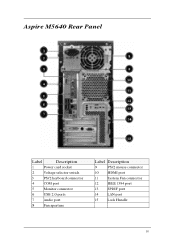
Aspire M5640 Rear Panel Label Description 1 Power card socket 2 Voltage selector switch 3 PS/2 keyboard connector 4 COM port 5 Monitor connector 6 USB 2.0 ports 7 Audio port 8 Fan aperture Label Description 9 PS/2 mouse connector 10 HDMI port 11 System Fan connector 12 IEEE 1394 port 13 SPDIF port 14 LAN port 15 Lock Handle 10
Aspire M5640 Rear Panel Label Description 1 Power card socket 2 Voltage selector switch 3 PS/2 keyboard connector 4 COM port 5 Monitor connector 6 USB 2.0 ports 7 Audio port 8 Fan aperture Label Description 9 PS/2 mouse connector 10 HDMI port 11 System Fan connector 12 IEEE 1394 port 13 SPDIF port 14 LAN port 15 Lock Handle 10
Service Guide for Aspire M1640 / M3640 / M5640
Page 18
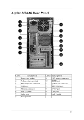
Aspire M3640 Rear Panel Label Description 1 Power card socket 2 Voltage selector switch 3 PS/2 keyboard connector 4 COM port 5 Monitor connector 6 USB 2.0 ports 7 Audio port 8 Fan aperture Label Description 9 PS/2 mouse connector 10 HDMI port 11 System Fan connector 12 IEEE 1394 port 13 SPDIF port 14 LAN port 15 Lock Handle 12
Aspire M3640 Rear Panel Label Description 1 Power card socket 2 Voltage selector switch 3 PS/2 keyboard connector 4 COM port 5 Monitor connector 6 USB 2.0 ports 7 Audio port 8 Fan aperture Label Description 9 PS/2 mouse connector 10 HDMI port 11 System Fan connector 12 IEEE 1394 port 13 SPDIF port 14 LAN port 15 Lock Handle 12
Service Guide for Aspire M1640 / M3640 / M5640
Page 20
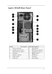
Aspire M1640 Rear Panel Label Description 1 Power card socket 2 Voltage selector switch 3 PS/2 keyboard connector 4 COM port 5 Monitor connector 6 USB 2.0 ports 7 Audio port Label Description 8 Fan aperture 9 PS/2 mouse connector 10 System Fan connector 11 IEEE1394 port 12 SPDIF port 13 LAN port 14 Lock Handle 14
Aspire M1640 Rear Panel Label Description 1 Power card socket 2 Voltage selector switch 3 PS/2 keyboard connector 4 COM port 5 Monitor connector 6 USB 2.0 ports 7 Audio port Label Description 8 Fan aperture 9 PS/2 mouse connector 10 System Fan connector 11 IEEE1394 port 12 SPDIF port 13 LAN port 14 Lock Handle 14
Service Guide for Aspire M1640 / M3640 / M5640
Page 21
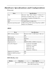
... CPU Clock in Sleep State in BIOS Setup is set to Enabled.) BIOS Item BIOS code programmer BIOS version BIOS ROM type BIOS ROM size Support protocol Device Boot Support Support to LS-120 drive Support to BIOS boot block feature Specification Phoenix Award or AMI Kernel with Acer skin V6.0 SPI Flash 4Mb SMBIOS (DMI) 2.4/DMI 2.0 (log file) - 1st priority: SATA HDD - 2nd priority: CD-ROM - 3rd priority: FDD - 4th priority: LAN - 5th priority: USB device YES YES BIOS Hotkey List Hotkey Del Function Enter BIOS Setup Utility...
... CPU Clock in Sleep State in BIOS Setup is set to Enabled.) BIOS Item BIOS code programmer BIOS version BIOS ROM type BIOS ROM size Support protocol Device Boot Support Support to LS-120 drive Support to BIOS boot block feature Specification Phoenix Award or AMI Kernel with Acer skin V6.0 SPI Flash 4Mb SMBIOS (DMI) 2.4/DMI 2.0 (log file) - 1st priority: SATA HDD - 2nd priority: CD-ROM - 3rd priority: FDD - 4th priority: LAN - 5th priority: USB device YES YES BIOS Hotkey List Hotkey Del Function Enter BIOS Setup Utility...
Service Guide for Aspire M1640 / M3640 / M5640
Page 22
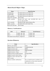
... socket Support memory type Support memory interface Support memory voltage Support memory module package Support to parity check feature Support to error correction code (ECC) feature Memory module combinations Specification 2 slot 512MB/1GB/2GB DDR2 DDR2 800MHz 1.8V 240-pin DDR2 Yes No You can install memory modules in any combination as long as they match the above specifications. 16 Main Board Major Chips Item North Bridge South Bridge APG controller Super I/O controller Audio controller LAN controller HDD controller Keyboard controller Specification...
... socket Support memory type Support memory interface Support memory voltage Support memory module package Support to parity check feature Support to error correction code (ECC) feature Memory module combinations Specification 2 slot 512MB/1GB/2GB DDR2 DDR2 800MHz 1.8V 240-pin DDR2 Yes No You can install memory modules in any combination as long as they match the above specifications. 16 Main Board Major Chips Item North Bridge South Bridge APG controller Super I/O controller Audio controller LAN controller HDD controller Keyboard controller Specification...
Service Guide for Aspire M1640 / M3640 / M5640
Page 23
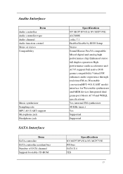
Audio Interface Item Audio controller Audio controller type Audio channel Audio function control Mono or stereo Compatibility Music synthesizer Sampling rate MPU-401 UART support Microphone jack Headphone jack SATA Interface Item SATA controller SATA controller resident bus Number of SATA channel Support bootable CD-ROM Specification NV MCP73PV/S & NV MCP73VE ALC888S codec 7.1 Enable/disable by BIOS Setup Stereo Sound Blaster Pro/16 compatible Mixed digital and analog high performance chip Enhanced stereo full duplex operation High...
Audio Interface Item Audio controller Audio controller type Audio channel Audio function control Mono or stereo Compatibility Music synthesizer Sampling rate MPU-401 UART support Microphone jack Headphone jack SATA Interface Item SATA controller SATA controller resident bus Number of SATA channel Support bootable CD-ROM Specification NV MCP73PV/S & NV MCP73VE ALC888S codec 7.1 Enable/disable by BIOS Setup Stereo Sound Blaster Pro/16 compatible Mixed digital and analog high performance chip Enhanced stereo full duplex operation High...
Service Guide for Aspire M1640 / M3640 / M5640
Page 24
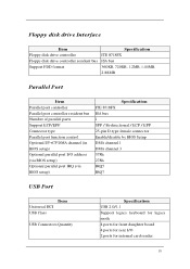
... Number of parallel parts Support ECP/EPP Connector type Parallel port function control Optional EV+CP DMA channel (in BIOS setup) Optional parallel port I/O address (via BIOS setup) Optional parallel port IRQ (via BIOS setup) Specification ITE 8718FX ISA bus 1 SPP / Bi-directional / ECP / EPP 25-pin D-type female connector Enable/disable by BIOS Setup DMA channel 1 DMA channel 3 378h 278h IRQ5 IRQ7 USB Port Universal HCI USB Class Item USB Connectors Quantity Specification USB 2.0/1.1 Support legacy keyboard for legacy mode 4 ports for front daughter board 4 ports for rear I/O 2 ports...
... Number of parallel parts Support ECP/EPP Connector type Parallel port function control Optional EV+CP DMA channel (in BIOS setup) Optional parallel port I/O address (via BIOS setup) Optional parallel port IRQ (via BIOS setup) Specification ITE 8718FX ISA bus 1 SPP / Bi-directional / ECP / EPP 25-pin D-type female connector Enable/disable by BIOS Setup DMA channel 1 DMA channel 3 378h 278h IRQ5 IRQ7 USB Port Universal HCI USB Class Item USB Connectors Quantity Specification USB 2.0/1.1 Support legacy keyboard for legacy mode 4 ports for front daughter board 4 ports for rear I/O 2 ports...
Service Guide for Aspire M1640 / M3640 / M5640
Page 27
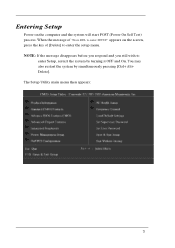
You may also restart the system by turning it OFF and On. Entering Setup Power on the screen, press the key of "Press DEL to enter SETUP" appears on the computer and the system will start POST (Power On Self Test) process. When the message of [Delete] to enter Setup, restart the system by simultaneously pressing [Ctrl+ Alt+ Delete]. NOTE: If the message disappears before you respond and you still wish to enter the setup menu. The Setup Utility main menu then appears: 21
You may also restart the system by turning it OFF and On. Entering Setup Power on the screen, press the key of "Press DEL to enter SETUP" appears on the computer and the system will start POST (Power On Self Test) process. When the message of [Delete] to enter Setup, restart the system by simultaneously pressing [Ctrl+ Alt+ Delete]. NOTE: If the message disappears before you respond and you still wish to enter the setup menu. The Setup Utility main menu then appears: 21
Service Guide for Aspire M1640 / M3640 / M5640
Page 28
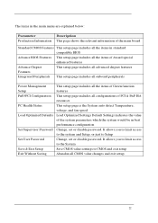
... System Save & Exit Setup Save CMOS value settings to Setup Set User Password Change, set or disable password. It allows you to limit access to the system and Setup, or just to CMOS and exit setup Exit Without Saving Abandon all configurations of PCI & PnP ISA resources PC Health Status This setup page is the System auto detect Temperature, voltage, and fan speed Load Optimized Defaults Load Optimized Settings Default Settings indicates the value...
... System Save & Exit Setup Save CMOS value settings to Setup Set User Password Change, set or disable password. It allows you to limit access to the system and Setup, or just to CMOS and exit setup Exit Without Saving Abandon all configurations of PCI & PnP ISA resources PC Health Status This setup page is the System auto detect Temperature, voltage, and fan speed Load Optimized Defaults Load Optimized Settings Default Settings indicates the value...
Service Guide for Aspire M1640 / M3640 / M5640
Page 32
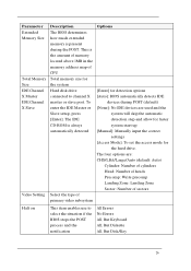
... the amount of memory located above 1MB in the memory address map of primary video subsystem Options [Enter] for detection options [Auto]: BIOS automatically detects IDE devices during the POST. The four options are used and the system will skip the automatic detection step and allow for faster system start up [Manual]: Manually input the correct settings [Access Mode]: To set the access mode for the system Hard disk drive connected to select the...
... the amount of memory located above 1MB in the memory address map of primary video subsystem Options [Enter] for detection options [Auto]: BIOS automatically detects IDE devices during the POST. The four options are used and the system will skip the automatic detection step and allow for faster system start up [Manual]: Manually input the correct settings [Access Mode]: To set the access mode for the system Hard disk drive connected to select the...
Service Guide for Aspire M1640 / M3640 / M5640
Page 34
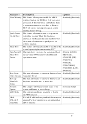
... access to the system and Setup, or just to load the disk operation system. Parameter Virus Warning Quick Power On Self Test Silent Boot First/Second/ Third Boot Device Boot From Other Devices Boot Up NumLock Status Security Option APIC Mode HDD S.M.A.R.T Capability Description This feature allows you to report any read/write errors and issue a warning when LDCM installed Options [Enabled], [Disabled] [Enabled], [Disabled] [Enabled], [Disabled] [Floppy], [LS120], [Hard Disk], [CD-ROM], [ZIP], [USB-FDD], [USB-ZIP], [USB-CDROM], [USB-HDD], [LAN], [Disabled] [Enabled], [Disabled] [Enabled...
... access to the system and Setup, or just to load the disk operation system. Parameter Virus Warning Quick Power On Self Test Silent Boot First/Second/ Third Boot Device Boot From Other Devices Boot Up NumLock Status Security Option APIC Mode HDD S.M.A.R.T Capability Description This feature allows you to report any read/write errors and issue a warning when LDCM installed Options [Enabled], [Disabled] [Enabled], [Disabled] [Enabled], [Disabled] [Floppy], [LS120], [Hard Disk], [CD-ROM], [ZIP], [USB-FDD], [USB-ZIP], [USB-CDROM], [USB-HDD], [LAN], [Disabled] [Enabled], [Disabled] [Enabled...
Service Guide for Aspire M1640 / M3640 / M5640
Page 39
... automatically determines the best mode for faster drive accesses. UDMA (Ultra DMA) is a DMA data transfer protocol that utilized ATA transfer protocol that utilizes ATA commands and the ATA bus to allow DMA commands to enable or disable DMA transfer access of IDE device (or IDE HDD) Options [Enabled], [Disabled] [Enabled], [Disabled] SATA 1/2 IDE Prefetch Mode Enable/Disable Serial-ATA 1 or Serial-ATA-2. The onboard IDE drive interfaces supports IDE prefetching, for each...
... automatically determines the best mode for faster drive accesses. UDMA (Ultra DMA) is a DMA data transfer protocol that utilized ATA transfer protocol that utilizes ATA commands and the ATA bus to allow DMA commands to enable or disable DMA transfer access of IDE device (or IDE HDD) Options [Enabled], [Disabled] [Enabled], [Disabled] SATA 1/2 IDE Prefetch Mode Enable/Disable Serial-ATA 1 or Serial-ATA-2. The onboard IDE drive interfaces supports IDE prefetching, for each...
Service Guide for Aspire M1640 / M3640 / M5640
Page 40
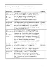
Parameter Description Options IDE HDD Block Mode SATA PORT Speed Settings Block mode is also called block transfer, multiple commands, or multiple sectors read /write per sector the drive can support. If your IDE hard drive supports block mode(most new drives do), select Enabled for automatic detection of the optimal number of SATA port. [Enabled], [Disabled] [Auto], Integrated Peripherals-Onboard Device Setup 34 This category allows you to determine the speed of block read /write.
Parameter Description Options IDE HDD Block Mode SATA PORT Speed Settings Block mode is also called block transfer, multiple commands, or multiple sectors read /write per sector the drive can support. If your IDE hard drive supports block mode(most new drives do), select Enabled for automatic detection of the optimal number of SATA port. [Enabled], [Disabled] [Auto], Integrated Peripherals-Onboard Device Setup 34 This category allows you to determine the speed of block read /write.
Service Guide for Aspire M1640 / M3640 / M5640
Page 41
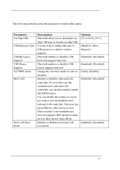
... free up an IRQ for other devices to shadow or Base Memory] memory. Use this item to change the type of [Shadow], [Base USB memory to use the motherboard's onboard LAN controller. Change the on board Audio to auto or [Auto], [Disable] disabled Enables or disables onboard LAN [Enabled], [Disabled] controller, If you wish to determine on [V1.1+V2.0], [V1.1] chip USB type or disable on board LAN [Enabled], [Disabled] boot ROM. 35 Parameter On Chip USB UDB Memory Type USB KB Legacy Support USB Mouse Support ALC888S Audio MAC LAN MAC LAN Boot ROM Description Options...
... free up an IRQ for other devices to shadow or Base Memory] memory. Use this item to change the type of [Shadow], [Base USB memory to use the motherboard's onboard LAN controller. Change the on board Audio to auto or [Auto], [Disable] disabled Enables or disables onboard LAN [Enabled], [Disabled] controller, If you wish to determine on [V1.1+V2.0], [V1.1] chip USB type or disable on board LAN [Enabled], [Disabled] boot ROM. 35 Parameter On Chip USB UDB Memory Type USB KB Legacy Support USB Mouse Support ALC888S Audio MAC LAN MAC LAN Boot ROM Description Options...

Service Guide for Aspire M1640 / M3640 / M5640
Page 43
... Mode used DMA Description Select Enabled if your system has a floppy disk controller (FDC) installed on the system board and you install an add-in FDC or the system has no floppy drive, select Disabled in this field appears. Half-duplex mode permits transmission in this menu. Select a logical COM port name and matching address for the serial port. Select the value required by the IR device connected...
... Mode used DMA Description Select Enabled if your system has a floppy disk controller (FDC) installed on the system board and you install an add-in FDC or the system has no floppy drive, select Disabled in this field appears. Half-duplex mode permits transmission in this menu. Select a logical COM port name and matching address for the serial port. Select the value required by the IR device connected...
Service Guide for Aspire M1640 / M3640 / M5640
Page 48
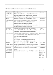
... operating system cannot boot Resources This item allows user to assign PCI IRQ for Plug and Play [Manual] compatible devices automatically or manually IRQ Resources When resource are controlled by manually, assign [Press Enter] each system interrupt a type , depending on the system. Maximum This field displays maximum payload size of device using the interrupt. It should be [Disabled], Palette Snoop left at "Disabled" unless a video device specifically [Enabled] requires the setting enabled upon installation...
... operating system cannot boot Resources This item allows user to assign PCI IRQ for Plug and Play [Manual] compatible devices automatically or manually IRQ Resources When resource are controlled by manually, assign [Press Enter] each system interrupt a type , depending on the system. Maximum This field displays maximum payload size of device using the interrupt. It should be [Disabled], Palette Snoop left at "Disabled" unless a video device specifically [Enabled] requires the setting enabled upon installation...


