Altos G310 Service Guide
Page 6
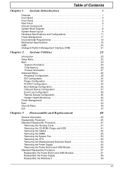
... 1 System Introduction 1 Features 1 Front Bezel 4 Front Panel 5 Rear Panel 6 Internal Components 7 System Block Diagram 8 System Board Layout 9 Hardware Specifications and Configurations 11 Power Management 17 Environmental Requirements 18 Mechanical Specifications 19 ASM 20 Intelligent Platform Management Interface (IPMI... the Cables 52 Removing the DIMM 53 Removing the System Fan 53 Removing the CPU 53 Removing the Mainboard and Extention Board 54 Removing the Power Supply 54 Removing the Power Button and USB Module 55 Standard Reassembly Procedure 57 Reassemble the Power...
... 1 System Introduction 1 Features 1 Front Bezel 4 Front Panel 5 Rear Panel 6 Internal Components 7 System Block Diagram 8 System Board Layout 9 Hardware Specifications and Configurations 11 Power Management 17 Environmental Requirements 18 Mechanical Specifications 19 ASM 20 Intelligent Platform Management Interface (IPMI... the Cables 52 Removing the DIMM 53 Removing the System Fan 53 Removing the CPU 53 Removing the Mainboard and Extention Board 54 Removing the Power Supply 54 Removing the Power Button and USB Module 55 Standard Reassembly Procedure 57 Reassemble the Power...
Altos G310 Service Guide
Page 16
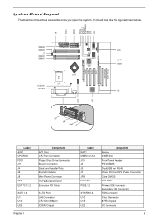
... and RJ45 Power Port and12V Power Connector Clear CMOS PCI Slots Primary IDE Connector Secondary IDE Connector FAN Connector Clock Generator 875P Chipset I/O Connector 9 System Board Layout The mainboard becomes accessible once you open the system. It should look like the figure shown below.
... and RJ45 Power Port and12V Power Connector Clear CMOS PCI Slots Primary IDE Connector Secondary IDE Connector FAN Connector Clock Generator 875P Chipset I/O Connector 9 System Board Layout The mainboard becomes accessible once you open the system. It should look like the figure shown below.
Altos G310 Service Guide
Page 18
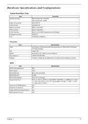
Hardware Specifications and Configurations System Board Major Chips Item System core logic Super I/O controller LAN controller Memory controller AGP controller E-IDE controller Keyboard controller RTC Controller NB (Canterwood): Intel 875P SB (...
Hardware Specifications and Configurations System Board Major Chips Item System core logic Super I/O controller LAN controller Memory controller AGP controller E-IDE controller Keyboard controller RTC Controller NB (Canterwood): Intel 875P SB (...
Altos G310 Service Guide
Page 20
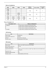
... interleave without dynamic mode LAN Interface Item LAN controller LAN controller resident bus LAN port Function control Intel 82547GI CSA Bus One RJ-45 on board (J5) Enable/disable by BIOS Setup Specification IDE Interface Item IDE controller IDE controller resident bus Number of IDE channel Supported IDE interface Supports LS...
... interleave without dynamic mode LAN Interface Item LAN controller LAN controller resident bus LAN port Function control Intel 82547GI CSA Bus One RJ-45 on board (J5) Enable/disable by BIOS Setup Specification IDE Interface Item IDE controller IDE controller resident bus Number of IDE channel Supported IDE interface Supports LS...

Altos G310 Service Guide
Page 26
Mechanical Specifications Dimensions W/O Bezel W/Bezel Color I/O ports Item Slots Main board Drive bays Switching power supply Material Indicators Switch Specification 186(W) X 424(H) X 460(D)mm 186(W) X 424(H) X 477(D)mm Black PS/2 keyboard port, PS/2 mouse port, two ...
Mechanical Specifications Dimensions W/O Bezel W/Bezel Color I/O ports Item Slots Main board Drive bays Switching power supply Material Indicators Switch Specification 186(W) X 424(H) X 460(D)mm 186(W) X 424(H) X 477(D)mm Black PS/2 keyboard port, PS/2 mouse port, two ...

Altos G310 Service Guide
Page 45
Onboard Device Configuration The onboard device configuration submenu displays the types of devices the system board can support. Parameter OnBoard LAN OnBoard S-ATA Description Gigabit ethernet support Serial ATA drive support Option Enabled Disabled Enabled Disabled 37 Chapter 2
Onboard Device Configuration The onboard device configuration submenu displays the types of devices the system board can support. Parameter OnBoard LAN OnBoard S-ATA Description Gigabit ethernet support Serial ATA drive support Option Enabled Disabled Enabled Disabled 37 Chapter 2
Altos G310 Service Guide
Page 50
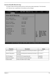
... Fan Speed Chassis Status Description Option Current CPU temperature detected by the sensor on 58 ° C/136 ° F the board Current board temperature detected by the sensor on 33 ° C/91 ° F the board Current CPU Fan speed detected 2646RPM Current System Fan speed detected 9121RPM Itemize the detail of each voltage Chapter...
... Fan Speed Chassis Status Description Option Current CPU temperature detected by the sensor on 58 ° C/136 ° F the board Current board temperature detected by the sensor on 33 ° C/91 ° F the board Current CPU Fan speed detected 2646RPM Current System Fan speed detected 9121RPM Itemize the detail of each voltage Chapter...

Altos G310 Service Guide
Page 62
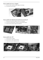
Removing the Power Supply 1. Chapter 3 54 Removing the four screws located on the rear chassis. 2. Remove the nine screws to the end. Take the power supply from the chassis. 3. Then gently to take CPU away from the mainboard. Then press down the locking lever to release the mainboard. 2. Removing the Mainboard and Extension Board 1. To separate the extension daughter board from the socket. 5. 4. Lift up the CPU locking lever until it is fully extended and take the mainboard from the chassis.
Removing the Power Supply 1. Chapter 3 54 Removing the four screws located on the rear chassis. 2. Remove the nine screws to the end. Take the power supply from the chassis. 3. Then gently to take CPU away from the mainboard. Then press down the locking lever to release the mainboard. 2. Removing the Mainboard and Extension Board 1. To separate the extension daughter board from the socket. 5. 4. Lift up the CPU locking lever until it is fully extended and take the mainboard from the chassis.

Altos G310 Service Guide
Page 64
Disconnect the USB cable. Remove the two screws. 13. Chapter 3 56 Remove the one screw to release the power button board from the power button board. 12. Disconnect the intrusion alarm cable. 11. Disconnect the cable from the bracket. 9. Take the power button board from the bracket. 14. Take the USB module away from the bracket. 10. 8.
Disconnect the USB cable. Remove the two screws. 13. Chapter 3 56 Remove the one screw to release the power button board from the power button board. 12. Disconnect the intrusion alarm cable. 11. Disconnect the cable from the bracket. 9. Take the power button board from the bracket. 14. Take the USB module away from the bracket. 10. 8.
Altos G310 Service Guide
Page 65
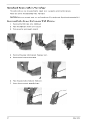
... button cable to the bracket. 3. Reconnect the USB cable to the bracket. 7. Reconnect the intrusion alarm cable. 6. Place the power button module to the USB board. 2. Secure the one screw to perform system service. Standard Reassembly Procedure This section tells you how to reassemble the system when you have turned off... all peripherals connected to the disassembly video, if available. Please also refer to it . 4. CAUTION: Before you proceed, make sure you need to fasten the board. 57 Altos G310
... button cable to the bracket. 3. Reconnect the USB cable to the bracket. 7. Reconnect the intrusion alarm cable. 6. Place the power button module to the USB board. 2. Secure the one screw to perform system service. Standard Reassembly Procedure This section tells you how to reassemble the system when you have turned off... all peripherals connected to the disassembly video, if available. Please also refer to it . 4. CAUTION: Before you proceed, make sure you need to fasten the board. 57 Altos G310
Altos G310 Service Guide
Page 67
Lift up the lever to the mainboard. 2. Then secure the four screws. Reconnect the extension daughter board to straight. 2. Reassemble the CPU 1. Secure the nine screws to place the mainboard with caution. 3. Aim at the Pin 1 mark to place the CPU. 3. Aim at the track to place the power supply to fasten the CPU. 59 Altos G310 Reassemble the Power Supply 1. Reassemble the Mainboard and Extension Board 1. Aim at the I/O shield position to fasten the mainboard. Press down the lever to the chassis. 2.
Lift up the lever to the mainboard. 2. Then secure the four screws. Reconnect the extension daughter board to straight. 2. Reassemble the CPU 1. Secure the nine screws to place the mainboard with caution. 3. Aim at the Pin 1 mark to place the CPU. 3. Aim at the track to place the power supply to fasten the CPU. 59 Altos G310 Reassemble the Power Supply 1. Reassemble the Mainboard and Extension Board 1. Aim at the I/O shield position to fasten the mainboard. Press down the lever to the chassis. 2.

Altos G310 Service Guide
Page 78
Chapter 5 Jumper and Connector Information Jumpers and Connectors Refer to the following figure for the location of the jumpers and connectors on the main board: Connector/Jumper Label AGP1 BAT1 CPUFAN DIMM 1,2,3,4 FDD1 J10 J11 Description AGP Slot Battery CPU Fan Connector DIMM Port Floppy Connector Front Panel Header Buzzer Connector Chapter 5 68
Chapter 5 Jumper and Connector Information Jumpers and Connectors Refer to the following figure for the location of the jumpers and connectors on the main board: Connector/Jumper Label AGP1 BAT1 CPUFAN DIMM 1,2,3,4 FDD1 J10 J11 Description AGP Slot Battery CPU Fan Connector DIMM Port Floppy Connector Front Panel Header Buzzer Connector Chapter 5 68


