
Altos G310 Service Guide
Page 6
... Memory 26 Product Information 27 Advanced Menu 28 Peripheral Configuration 29 IDE Configuration 30 Floppy Configuration 33 PCI/PnP Configuration 34 Boot Settings Configuration 35 Onboard Device Configuration 37 Event Log Configuration 38 Remote Access Configuration 40 System Health Monitoring 42 Power Management 43 Boot 44 Security Menu 46 Exit 47 Chapter 3 Disassemble and Replacement 48 General Information 49 Disassembly Flowchart 50 Standard Disassembly Procedure 51 Removing the Housing Cover 51 Removing the CD-ROM, Floppy and HDD 51 Removing the Cables...
... Memory 26 Product Information 27 Advanced Menu 28 Peripheral Configuration 29 IDE Configuration 30 Floppy Configuration 33 PCI/PnP Configuration 34 Boot Settings Configuration 35 Onboard Device Configuration 37 Event Log Configuration 38 Remote Access Configuration 40 System Health Monitoring 42 Power Management 43 Boot 44 Security Menu 46 Exit 47 Chapter 3 Disassemble and Replacement 48 General Information 49 Disassembly Flowchart 50 Standard Disassembly Procedure 51 Removing the Housing Cover 51 Removing the CD-ROM, Floppy and HDD 51 Removing the Cables...
Altos G310 Service Guide
Page 7
... HDD 61 Chapter 4 Troubleshooting 62 Bootblock Linitialization Code Checkpoints 62 Bootblock Recovery Code Checkpoints 64 POST Code Checkpoints 65 Beep Codes 67 Chapter 5 Jumper and Connector Information 68 Jumpers and Connectors 68 Front Panel I/O and LED 74 Chapter 6 FRU (Field Replaceable Unit) List 80 Altos G310 Exploded Diagram 81 Part List 82 Appendix A Model Definition and Configuration 86 Appendix B Test Compatible Components 87 Windows NT4.0+SP6 Environment Test 88 Windows 2000 Advanced Server Environment Test 90 Windows 2003 Environment Test 92 Windows...
... HDD 61 Chapter 4 Troubleshooting 62 Bootblock Linitialization Code Checkpoints 62 Bootblock Recovery Code Checkpoints 64 POST Code Checkpoints 65 Beep Codes 67 Chapter 5 Jumper and Connector Information 68 Jumpers and Connectors 68 Front Panel I/O and LED 74 Chapter 6 FRU (Field Replaceable Unit) List 80 Altos G310 Exploded Diagram 81 Part List 82 Appendix A Model Definition and Configuration 86 Appendix B Test Compatible Components 87 Windows NT4.0+SP6 Environment Test 88 Windows 2000 Advanced Server Environment Test 90 Windows 2003 Environment Test 92 Windows...
Altos G310 Service Guide
Page 8
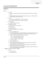
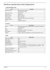
... I/O Controller Hub (ICH5-R) ! National Semiconductor PC87431M 1. SMBUS Management 3. Memory ! Support for an Intel Pentium 4 processor with unbuffered ECC support. ! Up to 3.4 GHz Pentium 4 (Prescott) processors. ! PC2700 (333 MHz): memory will run at full speed requires an Intel Pentium 4 processor with 800 MHz system bus frequency. ! Nothwood: 512 KB ! Supporting 533MHz FSB 2.8GHz Pentium 4(Northwood) processor, or 800MHz FSB 3.0 to 4 GB utilizing 512 Mb technology ! Temperature/Voltage/Fan sensors monitoring...
... I/O Controller Hub (ICH5-R) ! National Semiconductor PC87431M 1. SMBUS Management 3. Memory ! Support for an Intel Pentium 4 processor with unbuffered ECC support. ! Up to 3.4 GHz Pentium 4 (Prescott) processors. ! PC2700 (333 MHz): memory will run at full speed requires an Intel Pentium 4 processor with 800 MHz system bus frequency. ! Nothwood: 512 KB ! Supporting 533MHz FSB 2.8GHz Pentium 4(Northwood) processor, or 800MHz FSB 3.0 to 4 GB utilizing 512 Mb technology ! Temperature/Voltage/Fan sensors monitoring...
Altos G310 Service Guide
Page 16
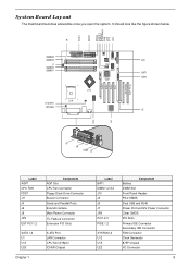
... EXT PCI 1,2 SATA 1,2 U1 U14 U20 Chapter 1 Component AGP Slot CPU Fan Connector Floppy Disck Drive Connector Buzzer Connector Serial and Parallel Ports Extend Interface Main Power Connector I2C Feature Connector Extension PCI Slots S-ATA Port LAN Connector CPU Slot (478pin) ICH5R Chipset Label BAT1 DIMM 1,2,3,4 J10 J3 J5 J7 JP8 PCI1,2,3 PIDE 1,2 SYSFAN1,2 U12 U15 U22 Component Battery DIMM Slot Front Panel Header PS/2 KBMS Dual USB and RJ45 Power Port and12V Power Connector Clear CMOS PCI Slots Primary IDE Connector Secondary IDE Connector FAN Connector Clock...
... EXT PCI 1,2 SATA 1,2 U1 U14 U20 Chapter 1 Component AGP Slot CPU Fan Connector Floppy Disck Drive Connector Buzzer Connector Serial and Parallel Ports Extend Interface Main Power Connector I2C Feature Connector Extension PCI Slots S-ATA Port LAN Connector CPU Slot (478pin) ICH5R Chipset Label BAT1 DIMM 1,2,3,4 J10 J3 J5 J7 JP8 PCI1,2,3 PIDE 1,2 SYSFAN1,2 U12 U15 U22 Component Battery DIMM Slot Front Panel Header PS/2 KBMS Dual USB and RJ45 Power Port and12V Power Connector Clear CMOS PCI Slots Primary IDE Connector Secondary IDE Connector FAN Connector Clock...
Altos G310 Service Guide
Page 18
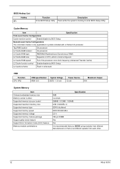
... configured FSB 400/533/800 MHz Processor voltage can be detected by the system without setting any jumper BIOS Item BIOS code programmer BIOS version BIOS ROM type BIOS ROM size BIOS ROM package Supported protocol Boot from CD-ROM feature Supports LS-120 drive Supports BIOS boot block feature BIOS password control Specification AMI V 8.0 Bulk mode flash ROM 512KB 32-pin PLCC package PCIX 1.0, PCI 2.2, APM1.2, VESA/DPMS (VBE/PM V1.1), SMBIOS 2.3, E-IDE 1.1, ACPI 1.0b, ESCD 1.03, PnP 1.0a, Bootable CD-ROM 1.0, USB...
... configured FSB 400/533/800 MHz Processor voltage can be detected by the system without setting any jumper BIOS Item BIOS code programmer BIOS version BIOS ROM type BIOS ROM size BIOS ROM package Supported protocol Boot from CD-ROM feature Supports LS-120 drive Supports BIOS boot block feature BIOS password control Specification AMI V 8.0 Bulk mode flash ROM 512KB 32-pin PLCC package PCIX 1.0, PCI 2.2, APM1.2, VESA/DPMS (VBE/PM V1.1), SMBIOS 2.3, E-IDE 1.1, ACPI 1.0b, ESCD 1.03, PnP 1.0a, Bootable CD-ROM 1.0, USB...
Altos G310 Service Guide
Page 19
... to enter BIOS Setup Utility. Cache Memory Item Specification First-Level Cache Configurations Cache function control Enable/disable by BIOS Setup L2 Cache scheme Fixed in write-back VRD Function CPU VRD VRM specification Typical Voltage VRM 10.0 0.8375 - 1.6 volt Power Source 12 volt Maximum Output 91A System Memory Item Onboard embedded memory size Memory socket number Supported memory size per socket Supported maximum memory size Supported memory type Supported memory speed Supported memory voltage Supported memory module package Support parity check feature Support Error...
... to enter BIOS Setup Utility. Cache Memory Item Specification First-Level Cache Configurations Cache function control Enable/disable by BIOS Setup L2 Cache scheme Fixed in write-back VRD Function CPU VRD VRM specification Typical Voltage VRM 10.0 0.8375 - 1.6 volt Power Source 12 volt Maximum Output 91A System Memory Item Onboard embedded memory size Memory socket number Supported memory size per socket Supported maximum memory size Supported memory type Supported memory speed Supported memory voltage Supported memory module package Support parity check feature Support Error...
Altos G310 Service Guide
Page 20
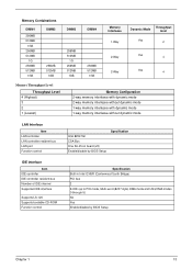
... memory interleave without dynamic mode 1-way memory interleave with dynamic mode 1-way memory interleave without dynamic mode LAN Interface Item LAN controller LAN controller resident bus LAN port Function control Intel 82547GI CSA Bus One RJ-45 on board (J5) Enable/disable by BIOS Setup Specification IDE Interface Item IDE controller IDE controller resident bus Number of IDE channel Supported IDE interface Supports LS-120 Supports bootable CD-ROM Function control Specification Built-in Intel ICH5R (Canterwood South Bridge) PCI...
... memory interleave without dynamic mode 1-way memory interleave with dynamic mode 1-way memory interleave without dynamic mode LAN Interface Item LAN controller LAN controller resident bus LAN port Function control Intel 82547GI CSA Bus One RJ-45 on board (J5) Enable/disable by BIOS Setup Specification IDE Interface Item IDE controller IDE controller resident bus Number of IDE channel Supported IDE interface Supports LS-120 Supports bootable CD-ROM Function control Specification Built-in Intel ICH5R (Canterwood South Bridge) PCI...
Altos G310 Service Guide
Page 21
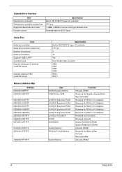
... bus Supported diskette drive formats Function control Specification Built-in NS PC87373 super I/O controller LPC bus 1.44MB, 2.88MB format and slim type diskette drive Enable/disable by BIOS Setup Serial Port Item Serial port controller Serial port controller resident bus Number of serial port Serial port locations Supports 16550 UART Connector type Optional serial port I/O address (via BIOS Setup) Optional serial port IRQ (via BIOS Setup) Specification Built-in NS PC87373 super I/O controller LPC bus 2 J4 Yes 9-pin D-type male connector 3F8h 2F8h 3E8h 2E8h IRQ 4 IRQ 11 Memory Address...
... bus Supported diskette drive formats Function control Specification Built-in NS PC87373 super I/O controller LPC bus 1.44MB, 2.88MB format and slim type diskette drive Enable/disable by BIOS Setup Serial Port Item Serial port controller Serial port controller resident bus Number of serial port Serial port locations Supports 16550 UART Connector type Optional serial port I/O address (via BIOS Setup) Optional serial port IRQ (via BIOS Setup) Specification Built-in NS PC87373 super I/O controller LPC bus 2 J4 Yes 9-pin D-type male connector 3F8h 2F8h 3E8h 2E8h IRQ 4 IRQ 11 Memory Address...
Altos G310 Service Guide
Page 24
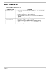
..., keyboard & mouse for HDD devices (0-15 minutes, time step = 1 minute) ! Disable H-sync and V-sync signals to control the VESA DPMS monitor ! Independent power management timer for Windows) ! Hard disk drive goes into STANDBY mode (for ATA standard interface) ! Resume recovery time: 7-10 seconds Chapter 1 17 Global power management timer (1-60 minutes) ! Disable V-sync to control the VESA DPMS monitor ! Hard disk drive goes into STANDBY mode (for ATA standard interface) ! Power Management Power Saving Mode Phenomenon List Power Saving Mode Device Standby mode...
..., keyboard & mouse for HDD devices (0-15 minutes, time step = 1 minute) ! Disable H-sync and V-sync signals to control the VESA DPMS monitor ! Independent power management timer for Windows) ! Hard disk drive goes into STANDBY mode (for ATA standard interface) ! Resume recovery time: 7-10 seconds Chapter 1 17 Global power management timer (1-60 minutes) ! Disable V-sync to control the VESA DPMS monitor ! Hard disk drive goes into STANDBY mode (for ATA standard interface) ! Power Management Power Saving Mode Phenomenon List Power Saving Mode Device Standby mode...
Altos G310 Service Guide
Page 28
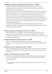
..., and sensor data record access, as well as the specification for intra-chassis communication with the CPU in the same way, whether there is added to six. Here sensor devices and cards with -the IPMI Event Log. Baseboard Management Controller (BMC) BMC is copied from five devices to manage, for common chassis and emergency management functions, including power and reset control, chassis status, events...
..., and sensor data record access, as well as the specification for intra-chassis communication with the CPU in the same way, whether there is added to six. Here sensor devices and cards with -the IPMI Event Log. Baseboard Management Controller (BMC) BMC is copied from five devices to manage, for common chassis and emergency management functions, including power and reset control, chassis status, events...
Altos G310 Service Guide
Page 31
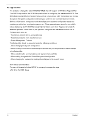
...: -- Hard drives, diskette drives, and peripherals -- When a configuration error is a ROM-based configuration utility that displays the system's configuration status and provides you with the values found in non-volatile battery-backed-up CMOS RAM that enables you are stored in CMOS. BIOS is detected by pressing the respective keys. Power Management Features This Setup utility should be able to initiate SETUP by the system and you to make changes to set system parameters. Enter the BIOS Setup...
...: -- Hard drives, diskette drives, and peripherals -- When a configuration error is a ROM-based configuration utility that displays the system's configuration status and provides you with the values found in non-volatile battery-backed-up CMOS RAM that enables you are stored in CMOS. BIOS is detected by pressing the respective keys. Power Management Features This Setup utility should be able to initiate SETUP by the system and you to make changes to set system parameters. Enter the BIOS Setup...
Altos G310 Service Guide
Page 32
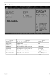
Main Menu Parameter BIOS Build Date BIOS Version SMBIOS Version System Time System Date Systeme Information Product Information Description The date when the BIOS build Version Control SMBIOS version of BIOS Use these items to set the correct date Display the system information Display the product information Options MM/DD/YY) N/A x.x.x (HH:MM:SS) (mm/dd/yy) Press [Enter] for sub menu Press [Enter] for sub menu Chapter 2 24 Use these items to set the correct time.
Main Menu Parameter BIOS Build Date BIOS Version SMBIOS Version System Time System Date Systeme Information Product Information Description The date when the BIOS build Version Control SMBIOS version of BIOS Use these items to set the correct date Display the system information Display the product information Options MM/DD/YY) N/A x.x.x (HH:MM:SS) (mm/dd/yy) Press [Enter] for sub menu Press [Enter] for sub menu Chapter 2 24 Use these items to set the correct time.
Altos G310 Service Guide
Page 33
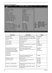
... present or not detected Hard Disk CDROM Not Detected Shows total installed memory size Press [Enter] for sub-menu Memory speed The memory interleave mode that is currently running Display BIOS assigned system resource for this device xxxxMB xxxxMHz One Way Two Way Four Way xxx, IRQx xxx,IRQx 25 Chapter 2 System Information Parameter Processor Type Processor Speed CPU ID Level 1 Cache Level 2 Cache Floppy Drive A Primary IDE Channel Master...
... present or not detected Hard Disk CDROM Not Detected Shows total installed memory size Press [Enter] for sub-menu Memory speed The memory interleave mode that is currently running Display BIOS assigned system resource for this device xxxxMB xxxxMHz One Way Two Way Four Way xxx, IRQx xxx,IRQx 25 Chapter 2 System Information Parameter Processor Type Processor Speed CPU ID Level 1 Cache Level 2 Cache Floppy Drive A Primary IDE Channel Master...
Altos G310 Service Guide
Page 47
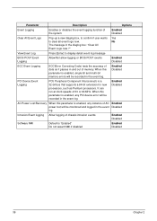
... user wants Yes to display detail event log message BIOS POST Event Logging Allow/Not allow logging or BIOS POST events Enabled Disabled ECC Event Logging ECC(Error Correcting Code) tests the accuracy of data as Pentium processors. View Event Log Press [Enter] to clear all event logs now. No The message in the event Disabled log. It can run at clock speeds of memory. Enabled Disabled Software NMI Default...
... user wants Yes to display detail event log message BIOS POST Event Logging Allow/Not allow logging or BIOS POST events Enabled Disabled ECC Event Logging ECC(Error Correcting Code) tests the accuracy of data as Pentium processors. View Event Log Press [Enter] to clear all event logs now. No The message in the event Disabled log. It can run at clock speeds of memory. Enabled Disabled Software NMI Default...
Altos G310 Service Guide
Page 48
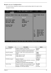
Selecting Serial enables remote access and opens a submenu to the syste's remote management features. Default is PC-ANSI, which is "Disabled" If Enabled, system will be deactivated. Parameter Remote Access Serial Port Number Serial Port Mode POST-Boot Support Terminal Type Description Enables or disables remote access. VT100 works for English as the select language. Remote Access Configuration The remote access configuration submenu lets you specify settings related to configuration system parameters. Default is "COM1" when remote access is set to "Serial" COM1 default ...
Selecting Serial enables remote access and opens a submenu to the syste's remote management features. Default is PC-ANSI, which is "Disabled" If Enabled, system will be deactivated. Parameter Remote Access Serial Port Number Serial Port Mode POST-Boot Support Terminal Type Description Enables or disables remote access. VT100 works for English as the select language. Remote Access Configuration The remote access configuration submenu lets you specify settings related to configuration system parameters. Default is "COM1" when remote access is set to "Serial" COM1 default ...
Altos G310 Service Guide
Page 50
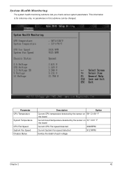
System Health Monitoring The system health monitoring submenu lets you check various system parameters. This information is for reference only, no parameters in this submenu can be changed. Parameter CPU Temperature System Temperature CPU Fan Speed System Fan Speed Chassis Status Description Option Current CPU temperature detected by the sensor on 58 ° C/136 ° F the board Current board temperature detected by the sensor...
System Health Monitoring The system health monitoring submenu lets you check various system parameters. This information is for reference only, no parameters in this submenu can be changed. Parameter CPU Temperature System Temperature CPU Fan Speed System Fan Speed Chassis Status Description Option Current CPU temperature detected by the sensor on 58 ° C/136 ° F the board Current board temperature detected by the sensor...
Altos G310 Service Guide
Page 59
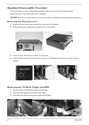
..., make sure you need to the disassembly video, if available. Disconnect the hard disk drive power cable and IDE cable 51 Altos G310 Standard Disassembly Procedure This section tells you how to disassemble the system when you have turned off the system and all peripherals connected to it from the chassis. Remove the two thumbscrews located at the rear end of the left panel rearward before detaching it . Removing the CD-ROM...
..., make sure you need to the disassembly video, if available. Disconnect the hard disk drive power cable and IDE cable 51 Altos G310 Standard Disassembly Procedure This section tells you how to disassemble the system when you have turned off the system and all peripherals connected to it from the chassis. Remove the two thumbscrews located at the rear end of the left panel rearward before detaching it . Removing the CD-ROM...
Altos G310 Service Guide
Page 75
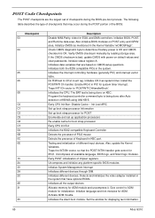
... controlling hardware (generally PIC) and interrupt vector table. Initializes the CPU. The BAT test is OK. Init Loal APIC Set up boot strap processor Information Set up application processors Re-enable cache for initialization. Initializes different devices. Initialize language and font modules for displaying text information. 65 Altos G310 The following table describes the type of different input devices. Also initialize BIOS modules on default values and clear passwords. Initialize CMOS...
... controlling hardware (generally PIC) and interrupt vector table. Initializes the CPU. The BAT test is OK. Init Loal APIC Set up boot strap processor Information Set up application processors Re-enable cache for initialization. Initializes different devices. Initialize language and font modules for displaying text information. 65 Altos G310 The following table describes the type of different input devices. Also initialize BIOS modules on default values and clear passwords. Initialize CMOS...
Altos G310 Service Guide
Page 76
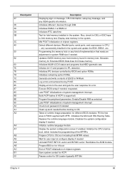
... RAM size if needed. Display errors to limit memory test. Initialize the CPU's before booting to OS Loader (typically INT19h) Chapter 4 66 Initializes IPL devices controlled by BIOS and option ROMs. Initializes remaining option ROMs. Generate and write contents of ESCD in the system. Build ACPI tables (if ACPI is supported) Program the peripheral parameters. Also, check for DEL or ESC keys to the user and gets the user...
... RAM size if needed. Display errors to limit memory test. Initialize the CPU's before booting to OS Loader (typically INT19h) Chapter 4 66 Initializes IPL devices controlled by BIOS and option ROMs. Initializes remaining option ROMs. Generate and write contents of ESCD in the system. Build ACPI tables (if ACPI is supported) Program the peripheral parameters. Also, check for DEL or ESC keys to the user and gets the user...
Altos G310 Service Guide
Page 85
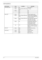
... alarm (Redundant cycle) FAN failure, Non-critical temperature and voltage) ON Critical alarm (Critical Power Modules Failure, Voltage Power Supply, Critical Temperature and voltage...) OFF System not Ready (Post error/ NMI event/ CPU or terminator missing...) Blink Hard Disk Drive Access OFF No Access ON LAN /No Access Blink LAN Access OFF Disconnect/ Idle 75 Altos G310 Green Green Amber Amber -ALL Green - Green Green - LED Definition LED Indicator Power/Sleep LED Status LED HDD LED LAN Activity Color Green...
... alarm (Redundant cycle) FAN failure, Non-critical temperature and voltage) ON Critical alarm (Critical Power Modules Failure, Voltage Power Supply, Critical Temperature and voltage...) OFF System not Ready (Post error/ NMI event/ CPU or terminator missing...) Blink Hard Disk Drive Access OFF No Access ON LAN /No Access Blink LAN Access OFF Disconnect/ Idle 75 Altos G310 Green Green Amber Amber -ALL Green - Green Green - LED Definition LED Indicator Power/Sleep LED Status LED HDD LED LAN Activity Color Green...


