
Service Guide
Page 6
... Exit 42 BIOS Flash Utility 43 Chapter 3 Machine Disassembly and Replacement 45 General Information 46 Before You Begin 46 Disassembly Procedure Flowchart 47 Removing the Battery Pack 50 Removing the Optical Module/HDD Module/Wireless Lan Card and LCD module . .51 Removing the Optical Module 51 Removing the HDD Module 51...
... Exit 42 BIOS Flash Utility 43 Chapter 3 Machine Disassembly and Replacement 45 General Information 46 Before You Begin 46 Disassembly Procedure Flowchart 47 Removing the Battery Pack 50 Removing the Optical Module/HDD Module/Wireless Lan Card and LCD module . .51 Removing the Optical Module 51 Removing the HDD Module 51...
Service Guide
Page 8
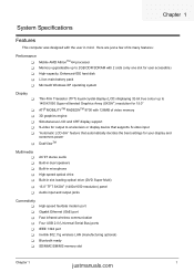
... processor T Memory upgradeable up to 2GB DDR SDRAM with 2 slots (only one slot for user accessible) T High-capacity, Enhanced-IDE hard disk T Li-Ion main battery pack T Microsoft Windows XP operating system Display T T T T T T T Thin-Film Transistor (TFT) liquid-crystal display (LCD) displaying 32-bit true colour up to a television or display...
... processor T Memory upgradeable up to 2GB DDR SDRAM with 2 slots (only one slot for user accessible) T High-capacity, Enhanced-IDE hard disk T Li-Ion main battery pack T Microsoft Windows XP operating system Display T T T T T T T Thin-Film Transistor (TFT) liquid-crystal display (LCD) displaying 32-bit true colour up to a television or display...
Service Guide
Page 18
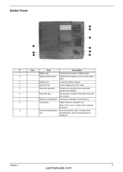
...: Don't cover or obstruct the opening of the fan. 9 Personal identification Insert a business card or similar-sized slot indentification card to remove the battery pack. 3 Battery lock Locks the battery in place. 4 Mini-PCI slot Slot for adding mini-PCI cards. 5 Hard disk protector Protects the hard disk from accidental bumps and vibration...
...: Don't cover or obstruct the opening of the fan. 9 Personal identification Insert a business card or similar-sized slot indentification card to remove the battery pack. 3 Battery lock Locks the battery in place. 4 Mini-PCI slot Slot for adding mini-PCI cards. 5 Hard disk protector Protects the hard disk from accidental bumps and vibration...

Service Guide
Page 19
Icon Function Caps lock Description Lights when Caps Lock is activated. Num lock Lights when Num Lock is activated. Lights orange when the battery is closed. The Power and Battery status indicators are visible even when the display is charging. 12 Chapter 1 Media Activity Power Battery Lights when the disc or optical drive is in standby mode. Lights gree when the power is on the front of the computer. Indicators The computer has three easy-to-read status indicators below the display screen. And two on and orange when the computer is activated.
Icon Function Caps lock Description Lights when Caps Lock is activated. Num lock Lights when Num Lock is activated. Lights orange when the battery is closed. The Power and Battery status indicators are visible even when the display is charging. 12 Chapter 1 Media Activity Power Battery Lights when the disc or optical drive is in standby mode. Lights gree when the power is on the front of the computer. Indicators The computer has three easy-to-read status indicators below the display screen. And two on and orange when the computer is activated.
Service Guide
Page 34
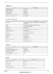
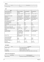
... keypads Windows logo key Internal & external keyboard work simultaneously NS 87570 C4 DARFON 84-/85-/88- key Yes Yes Specification Battery Item Vendor & model name Battery Type Pack capacity Cell voltage Number of battery cell Package configuration Specification Simplo/Sanyo Li-ion 4400 Ah 3.7V/cell 8 4 cells in series, 2 series in -one card...
... keypads Windows logo key Internal & external keyboard work simultaneously NS 87570 C4 DARFON 84-/85-/88- key Yes Yes Specification Battery Item Vendor & model name Battery Type Pack capacity Cell voltage Number of battery cell Package configuration Specification Simplo/Sanyo Li-ion 4400 Ah 3.7V/cell 8 4 cells in series, 2 series in -one card...
Service Guide
Page 35
Battery Item Package voltage 14.8V Specification LCD Item Vendor & model name Screen Diagonal (mm) Active Area (mm) Display resolution (pixels) Pixel Pitch Pixel Arrangement Display ...
Battery Item Package voltage 14.8V Specification LCD Item Vendor & model name Screen Diagonal (mm) Active Area (mm) Display resolution (pixels) Pixel Pitch Pixel Arrangement Display ...
Service Guide
Page 37
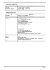
... Weight I/O Ports Item Drive Bays Material Indicators Switch Specification 330(W) x 272(D) x 31.8(H)mm 6.64lbs (3.01kg) for 15.1"LCD model with battery One Card bus type II slot One RJ-11 jack for 56Kbps fax/modem One RJ-45 jack for LAN One DC-in jack for...NTSC/PAL) output port 4-in-1 Card Reader (Manufacture optional) FIR (Fast Infred) port 100-pin expansion port supporting Acer EasyPort or I/O port replicator One Plastic There are 9 LEDs totally: Caps lock, Num lock, media activity, power, battery, InviLink, Bluetooth, 4-in-1 status, and optical disc access indicators Power 30 Chapter 1
... Weight I/O Ports Item Drive Bays Material Indicators Switch Specification 330(W) x 272(D) x 31.8(H)mm 6.64lbs (3.01kg) for 15.1"LCD model with battery One Card bus type II slot One RJ-11 jack for 56Kbps fax/modem One RJ-45 jack for LAN One DC-in jack for...NTSC/PAL) output port 4-in-1 Card Reader (Manufacture optional) FIR (Fast Infred) port 100-pin expansion port supporting Acer EasyPort or I/O port replicator One Plastic There are 9 LEDs totally: Caps lock, Num lock, media activity, power, battery, InviLink, Bluetooth, 4-in-1 status, and optical disc access indicators Power 30 Chapter 1
Service Guide
Page 50
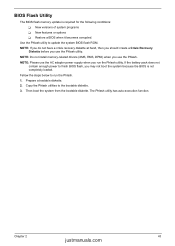
... justmanuals.com Fellow the steps below to finish BIOS flash, you use the Phlash utility. Then boot the system from the bootable diskette. If the battery pack does not contain enough power to run the Phlash utility.
... justmanuals.com Fellow the steps below to finish BIOS flash, you use the Phlash utility. Then boot the system from the bootable diskette. If the battery pack does not contain enough power to run the Phlash utility.

Service Guide
Page 53
General Information Before You Begin Before proceeding with the disassembly procedure, make sure that you disconnect different FFC/FPC/connectors. 46 Chapter 3 Remove the battery pack. Unplug the AC adapter and all peripherals. 2. NOTE: Ferrari 3200 series product uses mylar or tape to fasten the FFC/FPC/connectors/cable, you may need to the system and all power and signal cables from the system. 3. Turn off the power to tear the tape or mylar before you do the following: 1.
General Information Before You Begin Before proceeding with the disassembly procedure, make sure that you disconnect different FFC/FPC/connectors. 46 Chapter 3 Remove the battery pack. Unplug the AC adapter and all peripherals. 2. NOTE: Ferrari 3200 series product uses mylar or tape to fasten the FFC/FPC/connectors/cable, you may need to the system and all power and signal cables from the system. 3. Turn off the power to tear the tape or mylar before you do the following: 1.
Service Guide
Page 54
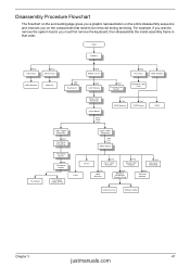
... Reader Hx1 Top Cover Shielding Tx2 HDD Bracket Hx2 Modem/ Bluetooth Combo Card Ex4 Thermal Module Antenna Line Modem Cable Chapter 3 47 justmanuals.com Start Battery Hx2 HDD Door Hx2 Dimm Door HDD Module Memory Hx2 Mx3 Keyboard Ox4 Middle Cover Sx4 LCD Module Hx3 Function Key Board Hx2 PCI Door...
... Reader Hx1 Top Cover Shielding Tx2 HDD Bracket Hx2 Modem/ Bluetooth Combo Card Ex4 Thermal Module Antenna Line Modem Cable Chapter 3 47 justmanuals.com Start Battery Hx2 HDD Door Hx2 Dimm Door HDD Module Memory Hx2 Mx3 Keyboard Ox4 Middle Cover Sx4 LCD Module Hx3 Function Key Board Hx2 PCI Door...
Service Guide
Page 57
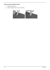
Slide the battery latch then remove the battery. 50 Chapter 3 Removing the Battery Pack 1. Release the battery lock. 2.
Slide the battery latch then remove the battery. 50 Chapter 3 Removing the Battery Pack 1. Release the battery lock. 2.
Service Guide
Page 70
Follow the instructions in the test items. 3. Remove the battery pack. 2. Disconnect the power adapter and install the charged battery pack; Go to main board. 2. A loose connection can cause an error. then check that power is supplied. 3. Connect the power adapter and ...and start the doagmpstotics program (please refer to the diagnostic memory in the message window. NOTE: Make sure that power is supplied by the battery pack. Memory check Memory errors might stop system operations, show error messages on page 64 Chapter 4 63 justmanuals.com Press F2 in the ...
Follow the instructions in the test items. 3. Remove the battery pack. 2. Disconnect the power adapter and install the charged battery pack; Go to main board. 2. A loose connection can cause an error. then check that power is supplied. 3. Connect the power adapter and ...and start the doagmpstotics program (please refer to the diagnostic memory in the message window. NOTE: Make sure that power is supplied by the battery pack. Memory check Memory errors might stop system operations, show error messages on page 64 Chapter 4 63 justmanuals.com Press F2 in the ...
Service Guide
Page 71
... problem. If yes, then replace switch board. Repeat the steps 1 and 2, for Current Power Source and Total Battery Power Remaining are correct. 3. Remove the battery pack and measure the voltage between battery terminals 1(+) and 6(ground). If the voltage is still less than 50% of time. 64 Chapter 4 If the...is connected well, then check if the FCC on Track Pad PCB. This symptom is applied to correct the problem. To check the battery charge operation, use the touchpad, the pointer drifts on touch pad PCB connects properly, then check if LS851 JP1 Pin6=5V are necessary...
... problem. If yes, then replace switch board. Repeat the steps 1 and 2, for Current Power Source and Total Battery Power Remaining are correct. 3. Remove the battery pack and measure the voltage between battery terminals 1(+) and 6(ground). If the voltage is still less than 50% of time. 64 Chapter 4 If the...is connected well, then check if the FCC on Track Pad PCB. This symptom is applied to correct the problem. To check the battery charge operation, use the touchpad, the pointer drifts on touch pad PCB connects properly, then check if LS851 JP1 Pin6=5V are necessary...
Service Guide
Page 73
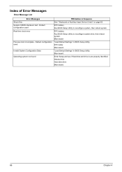
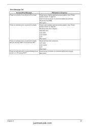
Main board "Load Default Settings" in BIOS Setup Utility. Default configuration used Real time clock error Previous boot incomplete - RTC battery Run BIOS Setup Utility to reconfigure system, then reboot system. Index of Error Messages Error Message List Error Messages Struck Key System CMOS checksum bad - ... configuration used Invalid System Configuration Data Operating system not found FRU/Action in Sequence See ""Keyboard or Auxiliary Input Device Check" on page 62 RTC battery Run BIOS Setup Utility to reconfigure system time, then reboot system.
Main board "Load Default Settings" in BIOS Setup Utility. Default configuration used Real time clock error Previous boot incomplete - RTC battery Run BIOS Setup Utility to reconfigure system, then reboot system. Index of Error Messages Error Message List Error Messages Struck Key System CMOS checksum bad - ... configuration used Invalid System Configuration Data Operating system not found FRU/Action in Sequence See ""Keyboard or Auxiliary Input Device Check" on page 62 RTC battery Run BIOS Setup Utility to reconfigure system time, then reboot system.
Service Guide
Page 74
...on and a blinking cursor Ensure every connector is blank. But you can see POST on LCD during POST. Reconnect the DIMM. Main board. Power source (battery pack and power adapter.) See "Power System Check" on page 63 Reconnect the LCD connector Hard disk drive LCD cable LCD inverter LCD Main board... beep Error Messages FRU/Action in Sequence Power-on indicator turns off and LCD is blank. Main board Chapter 4 67 justmanuals.com Power source (battery pack and power adapter.) See "Power System Check" on page 63 Ensure every connector is connected tightly and correctly.
...on and a blinking cursor Ensure every connector is blank. But you can see POST on LCD during POST. Reconnect the DIMM. Main board. Power source (battery pack and power adapter.) See "Power System Check" on page 63 Reconnect the LCD connector Hard disk drive LCD cable LCD inverter LCD Main board... beep Error Messages FRU/Action in Sequence Power-on indicator turns off and LCD is blank. Main board Chapter 4 67 justmanuals.com Power source (battery pack and power adapter.) See "Power System Check" on page 63 Ensure every connector is connected tightly and correctly.

Service Guide
Page 79
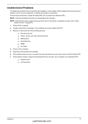
.... The system cannot power-off , then the main board is overheat (Heat sink or fan). See "Power System Check" on page 63. Battery pack Power adapter CPU Main board In Windows XP operating system, hold and press the power switch for more than 4 seconds. Main board 72...then reboot the system. Keyboard (if the brightness function key doesn't work ). Main board Power source (battery pack and power adapter). Verify OS in Sequence Power source (battery pack and power adapter). Battery pack AC adapter See if the thermal module is OK. Reconnect the LCD connectors. See "Power System...
.... The system cannot power-off , then the main board is overheat (Heat sink or fan). See "Power System Check" on page 63. Battery pack Power adapter CPU Main board In Windows XP operating system, hold and press the power switch for more than 4 seconds. Main board 72...then reboot the system. Keyboard (if the brightness function key doesn't work ). Main board Power source (battery pack and power adapter). Verify OS in Sequence Power source (battery pack and power adapter). Battery pack AC adapter See if the thermal module is OK. Reconnect the LCD connectors. See "Power System...

Service Guide
Page 80
... enter hibernation mode The system doesn't enter standby mode after closing the lid of Power Option Properties Lid close switch in Sequence See "Check the Battery Pack" on , but you hear two long beeps: "B--, B--" and the LCD is damaged. System can 't be inserted or ejected Action in ...Speaker Main board Speaker Main board Audio driver Volume control in Sequence Enter BIOS Setup Utility to execute "Load Default Settings" then reboot system. Battery pack Main board ODD/HDD/FDD/RAM module Main board PCMCIA-Related Symptoms Symptom / Error System cannot detect the PC Card (PCMCIA) PCMCIA ...
... enter hibernation mode The system doesn't enter standby mode after closing the lid of Power Option Properties Lid close switch in Sequence See "Check the Battery Pack" on , but you hear two long beeps: "B--, B--" and the LCD is damaged. System can 't be inserted or ejected Action in ...Speaker Main board Speaker Main board Audio driver Volume control in Sequence Enter BIOS Setup Utility to execute "Load Default Settings" then reboot system. Battery pack Main board ODD/HDD/FDD/RAM module Main board PCMCIA-Related Symptoms Symptom / Error System cannot detect the PC Card (PCMCIA) PCMCIA ...

Service Guide
Page 81
...BIOS Setup Utility to execute "Load Default Settings" then reboot the system. Check if the battery is low. Action in Sequence The system doesn't resume from hibernation/ standby mode. Main board Battery fuel gauge in Sequence Enter BIOS Setup Utility to execute "Load Default Settings" then reboot ...Windows doesn't go higher than 90%. Hard disk drive Main board The system doesn't resume from Standby/Hibernation mode. Refresh battery (continue use battery until power off, then charge battery). Battery pack Main board System hangs intermittently. Run printer self-test.
...BIOS Setup Utility to execute "Load Default Settings" then reboot the system. Check if the battery is low. Action in Sequence The system doesn't resume from hibernation/ standby mode. Main board Battery fuel gauge in Sequence Enter BIOS Setup Utility to execute "Load Default Settings" then reboot ...Windows doesn't go higher than 90%. Hard disk drive Main board The system doesn't resume from Standby/Hibernation mode. Refresh battery (continue use battery until power off, then charge battery). Battery pack Main board System hangs intermittently. Run printer self-test.
Service Guide
Page 84
... these procedures to isolate the failing FRU (do not isolate non-defective FRU). If the problem remains, replace the following devices: T Non-Acer devices T Printer, mouse, and other external devices T Battery pack T Hard disk drive T DIMM T PC Cards 4. NOTE: Verify that the power supply being used at a time until you find the...
... these procedures to isolate the failing FRU (do not isolate non-defective FRU). If the problem remains, replace the following devices: T Non-Acer devices T Printer, mouse, and other external devices T Battery pack T Hard disk drive T DIMM T PC Cards 4. NOTE: Verify that the power supply being used at a time until you find the...
Service Guide
Page 92
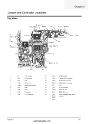
Jumper and Connector Locations Top View 3 2 4 5 6 7 Chapter 5 18 1 17 16 8 10 9 11 12 13 15 14 1 U4 CPU socket 2 CN1 S-video port 3 CN4 CRT 4 CN3 Printer port 5 CN30 EazyPort connector 6 CN2 RJ45 7 CN2 RJ11 8 CN6 Power jack 9 CN8 LCD connector 10 CN15 DIMM Socket 11 CN17 Optical drive connector 12 CN19 Keyboard connector 13 CN20 Main battery connector 14 U14 FIR 15 CN21 HDD connector 16 CON1 PCMCIA slot 17 CN16 IEEE 1394 port 18 CN9, Four USB ports (from top to CN11, bottom) CN13, CN14 Chapter 5 85 justmanuals.com
Jumper and Connector Locations Top View 3 2 4 5 6 7 Chapter 5 18 1 17 16 8 10 9 11 12 13 15 14 1 U4 CPU socket 2 CN1 S-video port 3 CN4 CRT 4 CN3 Printer port 5 CN30 EazyPort connector 6 CN2 RJ45 7 CN2 RJ11 8 CN6 Power jack 9 CN8 LCD connector 10 CN15 DIMM Socket 11 CN17 Optical drive connector 12 CN19 Keyboard connector 13 CN20 Main battery connector 14 U14 FIR 15 CN21 HDD connector 16 CON1 PCMCIA slot 17 CN16 IEEE 1394 port 18 CN9, Four USB ports (from top to CN11, bottom) CN13, CN14 Chapter 5 85 justmanuals.com


