

Service Guide
Page 6
... BIOS Utility 32 Infomation 33 Main 34 Advanced 36 Security 37 Boot 41 Exit 42 BIOS Flash Utility 43 Chapter 3 Machine Disassembly and Replacement 45 General Information 46 Before You Begin 46 Disassembly Procedure Flowchart 47 Removing the Battery Pack 50 Removing the Optical Module/HDD Module/Wireless Lan Card and LCD module . .51 Removing the Optical Module 51 Removing the HDD Module 51 Removing the Wireless LAN Card 51 Removing the LCD Module 52 Disassembling the Main Unit 53 Remove the function key board and the keyboard...
... BIOS Utility 32 Infomation 33 Main 34 Advanced 36 Security 37 Boot 41 Exit 42 BIOS Flash Utility 43 Chapter 3 Machine Disassembly and Replacement 45 General Information 46 Before You Begin 46 Disassembly Procedure Flowchart 47 Removing the Battery Pack 50 Removing the Optical Module/HDD Module/Wireless Lan Card and LCD module . .51 Removing the Optical Module 51 Removing the HDD Module 51 Removing the Wireless LAN Card 51 Removing the LCD Module 52 Disassembling the Main Unit 53 Remove the function key board and the keyboard...
Service Guide
Page 7
...-FRU Error Message 72 Intermittent Problems 76 Undetermined Problems 77 How to Build NAPP Master Hard Disc Drive 78 CD to Disk Recovery 78 Disk to Disk Recovery 81 Chapter 5 Jumper and Connector Locations 85 Top View 85 Bottom View 86 Chapter 6 FRU (Field Replaceable Unit) List 87 Exploded Diagram 88 Appendix A Model Definition and Configuration 96 Ferrari 3200 Series 96 Appendix B Test Compatible Components 97 Microsoft® Windows®...
...-FRU Error Message 72 Intermittent Problems 76 Undetermined Problems 77 How to Build NAPP Master Hard Disc Drive 78 CD to Disk Recovery 78 Disk to Disk Recovery 81 Chapter 5 Jumper and Connector Locations 85 Top View 85 Bottom View 86 Chapter 6 FRU (Field Replaceable Unit) List 87 Exploded Diagram 88 Appendix A Model Definition and Configuration 96 Ferrari 3200 Series 96 Appendix B Test Compatible Components 97 Microsoft® Windows®...

Service Guide
Page 13
Front Open View # 1 2 3 4 5 6 7 8 9 6 Icon Item Display screen Power button Touchpad Click buttons (left and right mouse buttons; Touch-sensitive pointing device which functions like the left , center and right) Palmrest Keyboard Status indicators Microphone Launch keys Description Also called LCD (liquid-crystal display), displays computer output. Comfortable support area for your computer. Chapter 1 The left and right buttons function like a computer mouse. LEDs (light-emitting diode) that turn on the computer. Internal microphone for launching Internet browser, E-mail program ...
Front Open View # 1 2 3 4 5 6 7 8 9 6 Icon Item Display screen Power button Touchpad Click buttons (left and right mouse buttons; Touch-sensitive pointing device which functions like the left , center and right) Palmrest Keyboard Status indicators Microphone Launch keys Description Also called LCD (liquid-crystal display), displays computer output. Comfortable support area for your computer. Chapter 1 The left and right buttons function like a computer mouse. LEDs (light-emitting diode) that turn on the computer. Internal microphone for launching Internet browser, E-mail program ...

Service Guide
Page 23
...volume. 16 Chapter 1 To activate hot keys, first hold down the Fn key. Hot Keys Using the Fn key with another key creates a hot key, providing a quick and convenient method for controlling various functions. Fn-F5 Fn-F6 Fn-F7 Display toggle Screen blank Touchpad toggle Switches display output between the display screen, external monitor (if connected) and both keys. Turns the internal touchpad on hot keys. Fn-F3 Fn-F4 Power management scheme toggle Switches the power management scheme used by the computer (function available if supported by operating system). Turns...
...volume. 16 Chapter 1 To activate hot keys, first hold down the Fn key. Hot Keys Using the Fn key with another key creates a hot key, providing a quick and convenient method for controlling various functions. Fn-F5 Fn-F6 Fn-F7 Display toggle Screen blank Touchpad toggle Switches display output between the display screen, external monitor (if connected) and both keys. Turns the internal touchpad on hot keys. Fn-F3 Fn-F4 Power management scheme toggle Switches the power management scheme used by the computer (function available if supported by operating system). Turns...

Service Guide
Page 33
... Chipset USB Compliancy Level OHCI Number of parallel port Location Connector type Parallel port function control Supports ECP/EPP/Bi-directional/Output only (PS/2 compatible) Optional ECP DMA channel (in BIOS Setup) Optional parallel port I/O address (in BIOS Setup) Optional parallel port IRQ (in BIOS Setup) Specification PC87393 1 Rear side 25-pin D-SUB Enable/Disable/Auto (BIOS or operating system chooses configuration) by BIOS Setup Note: Depending on your operating system, disabling an unused device may help free system resources for fixed resolution displays (e.g. panels...
... Chipset USB Compliancy Level OHCI Number of parallel port Location Connector type Parallel port function control Supports ECP/EPP/Bi-directional/Output only (PS/2 compatible) Optional ECP DMA channel (in BIOS Setup) Optional parallel port I/O address (in BIOS Setup) Optional parallel port IRQ (in BIOS Setup) Specification PC87393 1 Rear side 25-pin D-SUB Enable/Disable/Auto (BIOS or operating system chooses configuration) by BIOS Setup Note: Depending on your operating system, disabling an unused device may help free system resources for fixed resolution displays (e.g. panels...

Service Guide
Page 36
... to enter Hibernation mode. Phenomenon T The buzzer beeps T The Sleep indicator lights up T All power shuts off T The display shuts off T Hard disk drive is not ready to enter Hibernation mode. Individual devices such as the CPU and hard disk may be power managed in the system are idle for a specified period. Display Standby Mode Keyboard, built-in standby mode. (spindle turned-off) Environmental Requirements Item Temperature Operating Non-operating Humidity Operating Non-operating Non-operating Vibration Specification +5~+35...
... to enter Hibernation mode. Phenomenon T The buzzer beeps T The Sleep indicator lights up T All power shuts off T The display shuts off T Hard disk drive is not ready to enter Hibernation mode. Individual devices such as the CPU and hard disk may be power managed in the system are idle for a specified period. Display Standby Mode Keyboard, built-in standby mode. (spindle turned-off) Environmental Requirements Item Temperature Operating Non-operating Humidity Operating Non-operating Non-operating Vibration Specification +5~+35...
Service Guide
Page 42
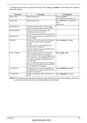
... disables Boot Menu function during Option: Disabled or Enabled POST. Format: HH:MM:SS (hour:minute:second) System Time Sets the system date. NOTE: The sub-items under each device will be in CRT (or projector) only mode. Chapter 2 35 justmanuals.com shows Summary Screen is disabled. Enabled: Customer Logo is displayed, and Summary Screen is disabled or enabled. Parameter System Time System Date System Memory Extended Memory Video Memory Quiet Boot Power on external video port...
... disables Boot Menu function during Option: Disabled or Enabled POST. Format: HH:MM:SS (hour:minute:second) System Time Sets the system date. NOTE: The sub-items under each device will be in CRT (or projector) only mode. Chapter 2 35 justmanuals.com shows Summary Screen is disabled. Enabled: Customer Logo is displayed, and Summary Screen is disabled or enabled. Parameter System Time System Date System Memory Extended Memory Video Memory Quiet Boot Power on external video port...
Service Guide
Page 45
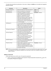
... the user wishes to enter a password, you set , this password protects the internal hard disk from unauthorized access. Defines whether a password is written to highlight the Set Supervisor Password parameter and press the e key. Option Clear or Set Clear or Set Disabled or Enabled Disabled or Enabled NOTE: When you may not be grayed out if the user password was used to enabled. If you forget your password, you are set , this password protects the BIOS Setup Utility from unauthorized access. The Set Supervisor Password...
... the user wishes to enter a password, you set , this password protects the internal hard disk from unauthorized access. Defines whether a password is written to highlight the Set Supervisor Password parameter and press the e key. Option Clear or Set Clear or Set Disabled or Enabled Disabled or Enabled NOTE: When you may not be grayed out if the user password was used to enabled. If you forget your password, you are set , this password protects the BIOS Setup Utility from unauthorized access. The Set Supervisor Password...
Service Guide
Page 46
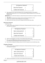
... the BIOS Setup Utility. The Set Password box appears: 2. Use the w and y keys to "Set". 4. IMPORTANT:Be very careful when typing your password because the characters do not appear on boot parameter. 5. Press e. Removing a Password Follow these steps: 1. When you are done, press u to enable the Password on the screen. 3. The password length can opt to save the changes and exit the BIOS Setup Utility. Changing a Password 1. After setting the password, the computer sets the User Password parameter...
... the BIOS Setup Utility. The Set Password box appears: 2. Use the w and y keys to "Set". 4. IMPORTANT:Be very careful when typing your password because the characters do not appear on boot parameter. 5. Press e. Removing a Password Follow these steps: 1. When you are done, press u to enable the Password on the screen. 3. The password length can opt to save the changes and exit the BIOS Setup Utility. Changing a Password 1. After setting the password, the computer sets the User Password parameter...
Service Guide
Page 49
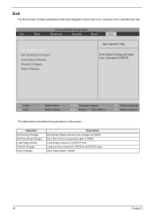
...; Select Menu F5/F6 Change Values Enter Select 4 Sub-Menu F9 Setup Defaults F10 Save and Exit The table below describes the parameters in this screen. Exit The Exit screen contains parameters that help safeguard and protect your computer from CMOS for all SETUP items. Save Setup Data to CMOS. Load previous values from unauthorized use. Exit utility without saving setup data to CMOS. 42 Chapter...
...; Select Menu F5/F6 Change Values Enter Select 4 Sub-Menu F9 Setup Defaults F10 Save and Exit The table below describes the parameters in this screen. Exit The Exit screen contains parameters that help safeguard and protect your computer from CMOS for all SETUP items. Save Setup Data to CMOS. Load previous values from unauthorized use. Exit utility without saving setup data to CMOS. 42 Chapter...

Service Guide
Page 75
... IDE Initialize Power Management Load alternate registers with initial POST values Restore CPU control word during warm boot Initialize PCI Bus Mastering devices Initialize keyboard controller BIOS ROM checksum Initialize cache before memory autosize 8254 timer initialization 8237 DMA controller initialization Reset Programmable Interrupt Controller Test DRAM refresh Test 8742 Keyboard Controller Set ES segment register to 4 GB Enable A20 line Autosize DRAM Initialize POST Memory Manager Clear 215 KB base RAM RAM failure...
... IDE Initialize Power Management Load alternate registers with initial POST values Restore CPU control word during warm boot Initialize PCI Bus Mastering devices Initialize keyboard controller BIOS ROM checksum Initialize cache before memory autosize 8254 timer initialization 8237 DMA controller initialization Reset Programmable Interrupt Controller Test DRAM refresh Test 8742 Keyboard Controller Set ES segment register to 4 GB Enable A20 line Autosize DRAM Initialize POST Memory Manager Clear 215 KB base RAM RAM failure...

Service Guide
Page 76
... devices Initialize all video adapters in system QuietBoot start (optional) Shadow video BIOS ROM Display BIOS copyright notice Display CPU type and speed Initialize EISA board Test keyboard Set key click if enabled Test for unexpected interrupts Initialize POST display service Display prompt "Press F2 to enter SETUP" Disable CPU cache Test RAM between 512 and 640 KB Test extended memory Test extended memory address lines Jump to User Patch1 Configure advanced cache registers Initialize Multi Processor APIC Enable external and CPU caches Setup...
... devices Initialize all video adapters in system QuietBoot start (optional) Shadow video BIOS ROM Display BIOS copyright notice Display CPU type and speed Initialize EISA board Test keyboard Set key click if enabled Test for unexpected interrupts Initialize POST display service Display prompt "Press F2 to enter SETUP" Disable CPU cache Test RAM between 512 and 640 KB Test extended memory Test extended memory address lines Jump to User Patch1 Configure advanced cache registers Initialize Multi Processor APIC Enable external and CPU caches Setup...

Service Guide
Page 77
...bus hard-disk controllers Jump to boot with INT 19 Initialize POST Error Manager (PEM) Initialize error logging Initialize error display function Initialize system error handler PnPnd dual CMOS (optional) Initialize notebook docking (optional) Initialize notebook docking late Force check (optional) Extended checksum (optional) Unknown interrupt Chapter 4 prepare to boot operating system One short beep before boot Terminate QuietBoot (optional) Check password (optional) Prepare Boot Initialize DMI parameters Initialize PnP Option ROMs Clear parity checkers Display MultiBoot menu Clear screen...
...bus hard-disk controllers Jump to boot with INT 19 Initialize POST Error Manager (PEM) Initialize error logging Initialize error display function Initialize system error handler PnPnd dual CMOS (optional) Initialize notebook docking (optional) Initialize notebook docking late Force check (optional) Extended checksum (optional) Unknown interrupt Chapter 4 prepare to boot operating system One short beep before boot Terminate QuietBoot (optional) Check password (optional) Prepare Boot Initialize DMI parameters Initialize PnP Option ROMs Clear parity checkers Display MultiBoot menu Clear screen...
Service Guide
Page 78
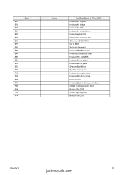
... the CPU Initialize the system timer Initialize system I/O Check force recovery boot Checksum BIOS ROM Go to BIOS Set Huge Segment Initialize Multi Processor Initialize OEM special code Initialize PIC and DMA Initialize Memory type Initialize Memory size Shadow Boot Block System memory test Initialize interrupt vectors Initialize Run Time Clock Initialize video Initialize System Management Mode Output one beep before boot Boot to Mini DOS Clear Huge Segment Boot...
... the CPU Initialize the system timer Initialize system I/O Check force recovery boot Checksum BIOS ROM Go to BIOS Set Huge Segment Initialize Multi Processor Initialize OEM special code Initialize PIC and DMA Initialize Memory type Initialize Memory size Shadow Boot Block System memory test Initialize interrupt vectors Initialize Run Time Clock Initialize video Initialize System Management Mode Output one beep before boot Boot to Mini DOS Clear Huge Segment Boot...

Service Guide
Page 79
... cable LCD inverter LCD Main board Reconnect the LCD cable LCD cable LCD Main board Indicator-Related Symptoms Symptom / Error Indicator incorrectly remains off or on . Battery pack Power adapter CPU Main board In Windows XP operating system, hold and press the power switch for more than 4 seconds. If the system can power off . Next, enter BIOS utility to execute "Load Setup Default Settings", then reboot system. Reconnect the LCD connectors. Main board Power source (battery pack and power adapter). Keyboard (if the brightness function key doesn't work HDD/CD-ROM drive Device driver...
... cable LCD inverter LCD Main board Reconnect the LCD cable LCD cable LCD Main board Indicator-Related Symptoms Symptom / Error Indicator incorrectly remains off or on . Battery pack Power adapter CPU Main board In Windows XP operating system, hold and press the power switch for more than 4 seconds. If the system can power off . Next, enter BIOS utility to execute "Load Setup Default Settings", then reboot system. Reconnect the LCD connectors. Main board Power source (battery pack and power adapter). Keyboard (if the brightness function key doesn't work HDD/CD-ROM drive Device driver...

Service Guide
Page 80
... PCMCIA slot is blocked Main board Memory-Related Symptoms Symptom / Error Memory count (size) appears different from the computer. Microphone cannot work Action in Sequence OS volume control Audio driver Speaker Main board Speaker Main board Audio driver Volume control in Windows XP Main board Power Management-Related Symptoms Symptom / Error The system will not enter hibernation mode The system doesn't enter standby mode after closing the lid of Power Option Properties Lid close switch in Windows XP Hard disk drive Main board Driver of...
... PCMCIA slot is blocked Main board Memory-Related Symptoms Symptom / Error Memory count (size) appears different from the computer. Microphone cannot work Action in Sequence OS volume control Audio driver Speaker Main board Speaker Main board Audio driver Volume control in Windows XP Main board Power Management-Related Symptoms Symptom / Error The system will not enter hibernation mode The system doesn't enter standby mode after closing the lid of Power Option Properties Lid close switch in Windows XP Hard disk drive Main board Driver of...

Service Guide
Page 81
... reboot system. Connect AC adapter then check if the system resumes from standby mode LCD cover switch after opening the lid of the portable computer. Hard disk drive Main board The system doesn't resume from Standby/Hibernation mode. Reconnect hard disk/CD-ROM drives/FDD or other peripherals. Keyboard Main board Reconnect touchpad cable. Refresh battery (continue use battery until power off, then charge battery). Battery pack Main board System hangs intermittently. Printer driver Printer cable Printer Main board Enter BIOS Setup Utility to execute "Load Default Settings...
... reboot system. Connect AC adapter then check if the system resumes from standby mode LCD cover switch after opening the lid of the portable computer. Hard disk drive Main board The system doesn't resume from Standby/Hibernation mode. Reconnect hard disk/CD-ROM drives/FDD or other peripherals. Keyboard Main board Reconnect touchpad cable. Refresh battery (continue use battery until power off, then charge battery). Battery pack Main board System hangs intermittently. Printer driver Printer cable Printer Main board Enter BIOS Setup Utility to execute "Load Default Settings...
Service Guide
Page 83
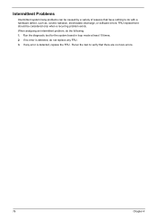
Intermittent Problems Intermittent system hang problems can be considered only when a recurring problem exists. When analyzing an intermittent problem, do not replace any error is detected, do the following: 1. Run the diagnostic test for the system board in loop mode at least 10 times. 2. Rerun the test to do with a hardware defect, such as: cosmic radiation, electrostatic discharge, or software errors. If...
Intermittent Problems Intermittent system hang problems can be considered only when a recurring problem exists. When analyzing an intermittent problem, do not replace any error is detected, do the following: 1. Run the diagnostic test for the system board in loop mode at least 10 times. 2. Rerun the test to do with a hardware defect, such as: cosmic radiation, electrostatic discharge, or software errors. If...

Service Guide
Page 110
... Disassembly Battery Pack 48 CD-ROM/DVD-ROM Module 53 Floppy Disk Drive 57 Procedure Flowchart 47 Display Standby Mode 29 E Embedded Numeric Keypad 14 Environmental Requirements 29 Error Symptom-to-Spare Part Index 65 External CD-ROM Drive Check 62 External Diskette Drive Check 62 F Features on System Specifications 1 Flash Utility 43 Floppy Disk removing the 57 FRU (Field Replaceable Unit) List 87 Exploded Diagram 88 H Hard Disk Standby Mode 29 Hibernation Mode 29 Hot Keys 13, 16 I Indicators 12 Intermittent Problems...
... Disassembly Battery Pack 48 CD-ROM/DVD-ROM Module 53 Floppy Disk Drive 57 Procedure Flowchart 47 Display Standby Mode 29 E Embedded Numeric Keypad 14 Environmental Requirements 29 Error Symptom-to-Spare Part Index 65 External CD-ROM Drive Check 62 External Diskette Drive Check 62 F Features on System Specifications 1 Flash Utility 43 Floppy Disk removing the 57 FRU (Field Replaceable Unit) List 87 Exploded Diagram 88 H Hard Disk Standby Mode 29 Hibernation Mode 29 Hot Keys 13, 16 I Indicators 12 Intermittent Problems...

Service Guide
Page 111
... Launch Keys 19 Lock Keys Using the Keyboard 13 M Mail on Launch Keys 19 Mechanical Specification 30 Media Activity on indicator 12 Memory Check 63 Model Definition 96 N Num lock on indicator 12 O Online Support Information 101 Outlook View 6 Bottom Panel 11 Front Open View 6 Front Panel 7 Left Panel 8 Rear Panel 10 Right Panel 9 P P1 on Launch Keys 19 P2 on Launch Keys 19 Parallel Port 26 PC Card 27 PCMCIA 27 Power on indicator 12 Power Management 29 Power...
... Launch Keys 19 Lock Keys Using the Keyboard 13 M Mail on Launch Keys 19 Mechanical Specification 30 Media Activity on indicator 12 Memory Check 63 Model Definition 96 N Num lock on indicator 12 O Online Support Information 101 Outlook View 6 Bottom Panel 11 Front Open View 6 Front Panel 7 Left Panel 8 Rear Panel 10 Right Panel 9 P P1 on Launch Keys 19 P2 on Launch Keys 19 Parallel Port 26 PC Card 27 PCMCIA 27 Power on indicator 12 Power Management 29 Power...


