Service Guide
Page 7
Table of Contents System Tour 1 Features 1 EL1210 Tour 3 Front Panel 3 Rear Panel 4 Internal Components 5 System LED Indicators 6 System Utilities 7 Phoenix BIOS Setup Utility 7 Entering BIOS setup 8 Navigating Through the Setup Utility 8 Setup Utility Menus 9 System Disassembly 27 Disassembly Requirements 27 Pre-disassembly Procedure 28 Main... 63 System Block Diagram 63 Board Layout 64 Mainboard 64 System Jumpers 65 FRU (Field Replaceable Unit) List 67 EL1210 Exploded Diagram 68 EL1210 FRU List (81.3V801.007G) 69 Technical Specifications 73 vii
Table of Contents System Tour 1 Features 1 EL1210 Tour 3 Front Panel 3 Rear Panel 4 Internal Components 5 System LED Indicators 6 System Utilities 7 Phoenix BIOS Setup Utility 7 Entering BIOS setup 8 Navigating Through the Setup Utility 8 Setup Utility Menus 9 System Disassembly 27 Disassembly Requirements 27 Pre-disassembly Procedure 28 Main... 63 System Block Diagram 63 Board Layout 64 Mainboard 64 System Jumpers 65 FRU (Field Replaceable Unit) List 67 EL1210 Exploded Diagram 68 EL1210 FRU List (81.3V801.007G) 69 Technical Specifications 73 vii
Service Guide
Page 15
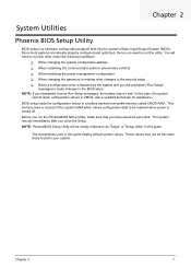
...The system reboots immediately after you have saved all open files. Chapter 2 7 This memory area is not part of the system RAM which allows configuration data to make sure that you close the Setup. You will be retained when power is a hardware configuration program ...built into the system's Basic Input/Output System (BIOS). NOTE: PhoenixBIOS Setup Utility will need to run this utility under the following conditions. When changing the system configuration settings ...
...The system reboots immediately after you have saved all open files. Chapter 2 7 This memory area is not part of the system RAM which allows configuration data to make sure that you close the Setup. You will be retained when power is a hardware configuration program ...built into the system's Basic Input/Output System (BIOS). NOTE: PhoenixBIOS Setup Utility will need to run this utility under the following conditions. When changing the system configuration settings ...

Service Guide
Page 16
... to the last page of submenu screen is user-configurable). The Setup Main menu will need to restart the server. Display the BIOS setup General Help panel. F5 - Entering BIOS setup 1. NOTE: Availability of a multiple page menu. + and - During POST, press F2. keys - Select a value for the currently selected field...
... to the last page of submenu screen is user-configurable). The Setup Main menu will need to restart the server. Display the BIOS setup General Help panel. F5 - Entering BIOS setup 1. NOTE: Availability of a multiple page menu. + and - During POST, press F2. keys - Select a value for the currently selected field...
Service Guide
Page 17
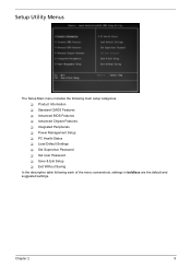
Setup Utility Menus The Setup Main menu includes the following main setup categories. Product Information Standard CMOS Features Advanced BIOS Features Advanced Chipset Features Integrated Peripherals Power Management Setup PC Health Status Load Default Settings Set Supervisor Password Set User Password Save & Exit Setup Exit Without Saving In the descriptive table following each of the menu screenshots, settings in boldface are the default and suggested settings. Chapter 2 9
Setup Utility Menus The Setup Main menu includes the following main setup categories. Product Information Standard CMOS Features Advanced BIOS Features Advanced Chipset Features Integrated Peripherals Power Management Setup PC Health Status Load Default Settings Set Supervisor Password Set User Password Save & Exit Setup Exit Without Saving In the descriptive table following each of the menu screenshots, settings in boldface are the default and suggested settings. Chapter 2 9

Service Guide
Page 18
These entries are for your reference only and are not user-configurable. Serial number of the BIOS setup utility. Version number of the system. Product Information The Product Information menu displays basic information about the system. Parameter System Manufacturer Product Name System S/N System BIOS Version BIOS Release Date Asset Tag Number Description Name of the manufacturer of this system. 10 Chapter 2 Date when the BIOS setup utility was released Asset tag number of the system. Product name of this system.
These entries are for your reference only and are not user-configurable. Serial number of the BIOS setup utility. Version number of the system. Product Information The Product Information menu displays basic information about the system. Parameter System Manufacturer Product Name System S/N System BIOS Version BIOS Release Date Asset Tag Number Description Name of the manufacturer of this system. 10 Chapter 2 Date when the BIOS setup utility was released Asset tag number of the system. Product name of this system.

Service Guide
Page 20
Set this parameter to Auto, BIOS automatically detect IDE/SATA devices during the POST. Auto None Set the HDD access mode. Auto Large 12 Chapter 2 SATA 1/2 Parameter IDE Auto Detection Extended IDE Drive Access Mode Description Option Press Enter to view detailed device information connected to the SATA 1/2 connectors When set to None when there are no IDE/SATA devices used.
Set this parameter to Auto, BIOS automatically detect IDE/SATA devices during the POST. Auto None Set the HDD access mode. Auto Large 12 Chapter 2 SATA 1/2 Parameter IDE Auto Detection Extended IDE Drive Access Mode Description Option Press Enter to view detailed device information connected to the SATA 1/2 connectors When set to None when there are no IDE/SATA devices used.
Service Guide
Page 21
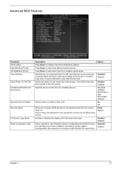
...will ask for access into this area. Allows the system to configure the CPU Virtualization feature. When set to write data into the BIOS setup menus. Option Disabled Enabled Enabled Disabled Hard Disk, CDROM, NVIDIA Boot Age, Removable, Disabled On Off Setup System Enabled Disabled ...Disabled Enabled Chapter 2 13 Advanced BIOS Features Parameter CPU Feature Hard Disk Boot Priority CD-ROM Boot Priority Virus Warning Quick Power On Self Test First/Second/Third/Fourth ...
...will ask for access into this area. Allows the system to configure the CPU Virtualization feature. When set to write data into the BIOS setup menus. Option Disabled Enabled Enabled Disabled Hard Disk, CDROM, NVIDIA Boot Age, Removable, Disabled On Off Setup System Enabled Disabled ...Disabled Enabled Chapter 2 13 Advanced BIOS Features Parameter CPU Feature Hard Disk Boot Priority CD-ROM Boot Priority Virus Warning Quick Power On Self Test First/Second/Third/Fourth ...
Service Guide
Page 24
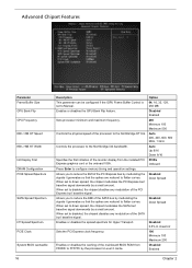
... by modulating the signals it generates so that the spikes are reduced to flatter curves. Enables or disables the caching of the mainboard BIOS ROM from the installed PCI Express graphics card or the onboard VGA. KissCntr 100 Minimum 100 Maximum 200 Disabled Enabled Chapter 2 Controls ...KBNB HT Speed KBNB HT Width Init Display First DRAM Configuration PCIE Spread Spectrum SATA Spread Spectrum HT Spread Spectrum PCIE Clock System BIOS cacheable 16 Description This parameter can be configured if the iGPU Frame Buffer Control is set to disabled, the chipset disables any modulation...
... by modulating the signals it generates so that the spikes are reduced to flatter curves. Enables or disables the caching of the mainboard BIOS ROM from the installed PCI Express graphics card or the onboard VGA. KissCntr 100 Minimum 100 Maximum 200 Disabled Enabled Chapter 2 Controls ...KBNB HT Speed KBNB HT Width Init Display First DRAM Configuration PCIE Spread Spectrum SATA Spread Spectrum HT Spread Spectrum PCIE Clock System BIOS cacheable 16 Description This parameter can be configured if the iGPU Frame Buffer Control is set to disabled, the chipset disables any modulation...

Service Guide
Page 30
Setup defaults are using low-speed memory chips or other kinds of resources consumption. Load Default Settings The Load Default Settings menu allows you choose to load the default settings for all BIOS setup parameters. If you are quite demanding in terms of low-performance components and you to load these settings, the system might not function properly. 22 Chapter 2
Setup defaults are using low-speed memory chips or other kinds of resources consumption. Load Default Settings The Load Default Settings menu allows you choose to load the default settings for all BIOS setup parameters. If you are quite demanding in terms of low-performance components and you to load these settings, the system might not function properly. 22 Chapter 2
Service Guide
Page 62
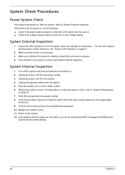
...6. If the problem is not evident, you can indicate the malfunction. Power on the front panel, which can try viewing the POST messages and BIOS event logs during the system startup. 54 Chapter 4 Refer to the system and AC source. Check if the voltage selector switch is... peripherals connected to their behaviour, see "System LED Indicators" on page 6. 2. Turn off the system and all cable connectors inside the system are Acer-qualified and supported. 10. If the system will power on , do the following: Check if the power cable is properly connected to ...
...6. If the problem is not evident, you can indicate the malfunction. Power on the front panel, which can try viewing the POST messages and BIOS event logs during the system startup. 54 Chapter 4 Refer to the system and AC source. Check if the voltage selector switch is... peripherals connected to their behaviour, see "System LED Indicators" on page 6. 2. Turn off the system and all cable connectors inside the system are Acer-qualified and supported. 10. If the system will power on , do the following: Check if the power cable is properly connected to ...

Service Guide
Page 63
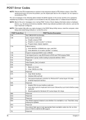
... the best tool for viewing AMIBIOS checkpoints. CMOS damaged. Beep codes are used when an error occurs before the system video has been initialized. BIOS damaged. CMOS checksum error. AMIBIOS displays the checkpoints in the bottom right corner of the screen during POST. VGA not installed or VGA error.... Beep codes will be generated by the BIOS to indicate a serious or fatal error to as the PC speaker. Chapter 4 55 This display method is OK. System is limited, since it...
... the best tool for viewing AMIBIOS checkpoints. CMOS damaged. Beep codes are used when an error occurs before the system video has been initialized. BIOS damaged. CMOS checksum error. AMIBIOS displays the checkpoints in the bottom right corner of the screen during POST. VGA not installed or VGA error.... Beep codes will be generated by the BIOS to indicate a serious or fatal error to as the PC speaker. Chapter 4 55 This display method is OK. System is limited, since it...
Service Guide
Page 64
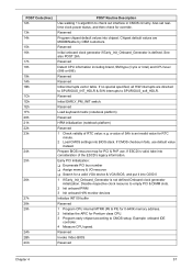
... type, and ECC Auto-detection of L2 cache (socket 7 or below) Expand compressed BIOS code to DRAM Call chipset hook to copy BIOS back to E000 and F000 shadow RAM Expand the X group codes locating in physical address 1000:0 Reserved Initial Superio_Earl_Init switch Reserved 1 Blank out... for Winbond 977 series Super I /O chops Reserved Reserved Reserved Test F000h segment shadow to "Undetermined Problems". The error messages in the BIOS Setup Utility menus, reset the computer, enter Setup and install Setup defaults or correct the error. NOTE: Most of memory installed. Some...
... type, and ECC Auto-detection of L2 cache (socket 7 or below) Expand compressed BIOS code to DRAM Call chipset hook to copy BIOS back to E000 and F000 shadow RAM Expand the X group codes locating in physical address 1000:0 Reserved Initial Superio_Earl_Init switch Reserved 1 Blank out... for Winbond 977 series Super I /O chops Reserved Reserved Reserved Test F000h segment shadow to "Undetermined Problems". The error messages in the BIOS Setup Utility menus, reset the computer, enter Setup and install Setup defaults or correct the error. NOTE: Most of memory installed. Some...
Service Guide
Page 65
... Initialization: Enumerate PCI bus number Assign memory & I/O resource Search for a valid VGA device & VGA BIOS, and put it into C000:0 1 If Early_Init_Onboard_Generator is valid, take into consideration of the ESCD's legacy information. Example: onboard IDE controller.... Reserved Load keyboard matrix (notebook platform) Reserved HPM initialization (notebook platform) Reserved 1 Check validity of 5Ah is defined. Prepare BIOS resource map for RTC minute. 2 Load CMOS settings into chipset. If no special specified, all H/W interrupts are MODBINable by OEM...
... Initialization: Enumerate PCI bus number Assign memory & I/O resource Search for a valid VGA device & VGA BIOS, and put it into C000:0 1 If Early_Init_Onboard_Generator is valid, take into consideration of the ESCD's legacy information. Example: onboard IDE controller.... Reserved Load keyboard matrix (notebook platform) Reserved HPM initialization (notebook platform) Reserved 1 Check validity of 5Ah is defined. Prepare BIOS resource map for RTC minute. 2 Load CMOS settings into chipset. If no special specified, all H/W interrupts are MODBINable by OEM...
Service Guide
Page 70
...'s Warranty (ITW) Returned material authorization procedures An overview of Acer notebook, desktop and server models including: Service guides for all models User's manuals Training materials BIOS updates Software utilities Spare parts lists Technical Announcement Bulletins..., fax, and email contacts for ways to optimize and improve our services, so if you can be obtained directly from Acer CSD Taiwan. If you are always looking for all the support services we have any suggestions or comments, please do not...
...'s Warranty (ITW) Returned material authorization procedures An overview of Acer notebook, desktop and server models including: Service guides for all models User's manuals Training materials BIOS updates Software utilities Spare parts lists Technical Announcement Bulletins..., fax, and email contacts for ways to optimize and improve our services, so if you can be obtained directly from Acer CSD Taiwan. If you are always looking for all the support services we have any suggestions or comments, please do not...


