Service Guide
Page 7
... Sink Fan Assembly 32 Removing the Processor 34 Removing the Optical Drive 36 Removing the Hard Disk Drive 38 Removing the Power Supply 41 Removing the Memory Modules 44 Removing the PCI Card 45 Removing the Front I/O and Card Reader Boards 47 Removing the Mainboard 51 System Troubleshooting 53 Hardware Diagnostic Procedure 53 System Check Procedures 54 Power System Check 54 System External Inspection 54 System Internal Inspection 54 Beep Codes 55 POST Error Codes 56 Online Support Information 62 System Block Diagram and Board Layout 63...
... Sink Fan Assembly 32 Removing the Processor 34 Removing the Optical Drive 36 Removing the Hard Disk Drive 38 Removing the Power Supply 41 Removing the Memory Modules 44 Removing the PCI Card 45 Removing the Front I/O and Card Reader Boards 47 Removing the Mainboard 51 System Troubleshooting 53 Hardware Diagnostic Procedure 53 System Check Procedures 54 Power System Check 54 System External Inspection 54 System Internal Inspection 54 Beep Codes 55 POST Error Codes 56 Online Support Information 62 System Block Diagram and Board Layout 63...
Service Guide
Page 9
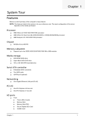
... modules Media storage DVD-ROM SATA drive Super-Multi SATA DVD drive 160 or 320 GB SATA hard disk drive Serial ATA controller Embedded SATA controllers Two SATA ports eSATA port (optional) Networking One Gigabit Ethernet LAN port (RJ-45) PCI I/O One PCI Express x16 bus slot One PCI Express x1 bus slot I/O ports Front Three USB 2.0 ports Memory Stick Memory Stick PRO Secure Digitial (SD) Card miniSD Card Chapter 1 1 The exact configuration...
... modules Media storage DVD-ROM SATA drive Super-Multi SATA DVD drive 160 or 320 GB SATA hard disk drive Serial ATA controller Embedded SATA controllers Two SATA ports eSATA port (optional) Networking One Gigabit Ethernet LAN port (RJ-45) PCI I/O One PCI Express x16 bus slot One PCI Express x1 bus slot I/O ports Front Three USB 2.0 ports Memory Stick Memory Stick PRO Secure Digitial (SD) Card miniSD Card Chapter 1 1 The exact configuration...
Service Guide
Page 10
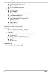
... front speakers jack Center speaker/subwoofer jack Surround L/R speaker jack Audio inside speaker jack or side speaker jack ESATA port (optional) Four USB 2.0 ports Gigabit LAN port VGA/monitor port Operating system and software Operating system options: Genuine Windows Vista® Ultimate (32/64-bit) Genuine Windows Vista Home Premium (32/64-bit) Applications Acer Empowering Technology (Acer eRecovery Management) Acer Arcade Live McAfee Internet Security...
... front speakers jack Center speaker/subwoofer jack Surround L/R speaker jack Audio inside speaker jack or side speaker jack ESATA port (optional) Four USB 2.0 ports Gigabit LAN port VGA/monitor port Operating system and software Operating system options: Genuine Windows Vista® Ultimate (32/64-bit) Genuine Windows Vista Home Premium (32/64-bit) Applications Acer Empowering Technology (Acer eRecovery Management) Acer Arcade Live McAfee Internet Security...
Service Guide
Page 12
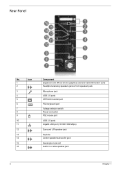
Rear Panel No. Icon 1 2 3 4 5 6 7 8 9 10 11 12 13 14 15 16 Component Expansion slot (Photo shows graphics card and network/modem card) Headphone/analog speakers jack or front speakers jack Microphone jack USB 2.0 ports CRT/LCD monitor port PS2 keyboard port Voltage selector switch Power connector PS2 mouse port USB 2.0 ports Gigabit LAN port (10/100/1000 Mbps) Surround L/R speaker jack Keyhole Center speaker/subwoofer jack Kensington lock slot Audio in or side speaker jack 4 Chapter 1
Rear Panel No. Icon 1 2 3 4 5 6 7 8 9 10 11 12 13 14 15 16 Component Expansion slot (Photo shows graphics card and network/modem card) Headphone/analog speakers jack or front speakers jack Microphone jack USB 2.0 ports CRT/LCD monitor port PS2 keyboard port Voltage selector switch Power connector PS2 mouse port USB 2.0 ports Gigabit LAN port (10/100/1000 Mbps) Surround L/R speaker jack Keyhole Center speaker/subwoofer jack Kensington lock slot Audio in or side speaker jack 4 Chapter 1
Service Guide
Page 15
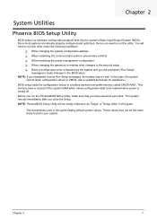
... the power management configuration When changing the password or making other changes to the security setup When a configuration error is a hardware configuration program built into the system's Basic Input/Output System (BIOS). Chapter 2 System Utilities Phoenix BIOS Setup Utility BIOS setup is detected by the system and you are already properly configured and optimized, there is not part of the system RAM which allows configuration data to as "Setup" or "Setup utility" in this case...
... the power management configuration When changing the password or making other changes to the security setup When a configuration error is a hardware configuration program built into the system's Basic Input/Output System (BIOS). Chapter 2 System Utilities Phoenix BIOS Setup Utility BIOS setup is detected by the system and you are already properly configured and optimized, there is not part of the system RAM which allows configuration data to as "Setup" or "Setup utility" in this case...
Service Guide
Page 21
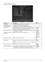
... to select hard disk boot device priority. Option Disabled Enabled Enabled Disabled Hard Disk, CDROM, NVIDIA Boot Age, Removable, Disabled On Off Setup System Enabled Disabled Disabled Enabled Chapter 2 13 Selects power on and the system reconfiguration has caused such a serious conflict that the OS cannot boot. Press Enter to skip certain test while booting. Enables or disables the display of the full screen boot logo. When set to configure the CPU Virtualization feature. Advanced BIOS Features Parameter CPU Feature Hard Disk Boot Priority CD-ROM Boot Priority Virus...
... to select hard disk boot device priority. Option Disabled Enabled Enabled Disabled Hard Disk, CDROM, NVIDIA Boot Age, Removable, Disabled On Off Setup System Enabled Disabled Disabled Enabled Chapter 2 13 Selects power on and the system reconfiguration has caused such a serious conflict that the OS cannot boot. Press Enter to skip certain test while booting. Enables or disables the display of the full screen boot logo. When set to configure the CPU Virtualization feature. Advanced BIOS Features Parameter CPU Feature Hard Disk Boot Priority CD-ROM Boot Priority Virus...
Service Guide
Page 24
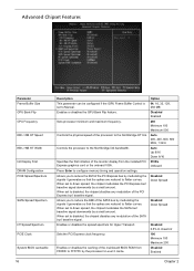
... 200, 400, 600, 800 MHz, 1 GHz Auto Up 8/16 Down 8/16 PCIEx Onboard Disabled Down Spread Disabled Down Spread Disabled 0.5% H. Enables or disables the GPU Bank Flip feature. Controls the physical speed of the mainboard BIOS ROM from the installed PCI Express graphics card or the onboard VGA. Specifies the first initiation of the SATA bus' baseline signal. Enables or disables the spread spectrum for Hyper Transport.
... 200, 400, 600, 800 MHz, 1 GHz Auto Up 8/16 Down 8/16 PCIEx Onboard Disabled Down Spread Disabled Down Spread Disabled 0.5% H. Enables or disables the GPU Bank Flip feature. Controls the physical speed of the mainboard BIOS ROM from the installed PCI Express graphics card or the onboard VGA. Specifies the first initiation of the SATA bus' baseline signal. Enables or disables the spread spectrum for Hyper Transport.

Service Guide
Page 25
.... Option Auto MaxMemClk Manual Disabled Enabled Per Channel Per CS Disabled Enabled Enabled Disabled Enabled Disabled Minimim 0000 Maximum 00FC Chapter 2 17 All synchronous memory devices can manually specify the memory clock frequency independent of the system bus frequency. Sets the CKE power saving through disasserting clock enable using system level or per channel basis. Allows you to enter a HEX number ranging from 0000 to MaxMemClk, you to auto mode, the...
.... Option Auto MaxMemClk Manual Disabled Enabled Per Channel Per CS Disabled Enabled Enabled Disabled Enabled Disabled Minimim 0000 Maximum 00FC Chapter 2 17 All synchronous memory devices can manually specify the memory clock frequency independent of the system bus frequency. Sets the CKE power saving through disasserting clock enable using system level or per channel basis. Allows you to enter a HEX number ranging from 0000 to MaxMemClk, you to auto mode, the...
Service Guide
Page 28
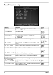
... ACPI state. Enables or disables to automatically start itself up after a period inactivity. Power Management Setup Parameter ACPI function ACPI Suspend Type Power Management Video Off Method HDD Power Down HDD Down in suspend mode. Set the system to wake up the system from a power saving mode using soft-off. Option Enabled Disabled S3 (STR) S1 (POS) Default User Define Min. Set a time when the hard disk drives will wake system from S1/ S3 state. Enables or disables the HDD power down function...
... ACPI state. Enables or disables to automatically start itself up after a period inactivity. Power Management Setup Parameter ACPI function ACPI Suspend Type Power Management Video Off Method HDD Power Down HDD Down in suspend mode. Set the system to wake up the system from a power saving mode using soft-off. Option Enabled Disabled S3 (STR) S1 (POS) Default User Define Min. Set a time when the hard disk drives will wake system from S1/ S3 state. Enables or disables the HDD power down function...
Service Guide
Page 31
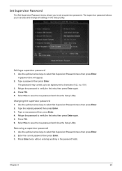
... arrow keys to select Set Supervisor Password menu then press Enter. Press F10. 6. Press F10. 5. Removing a supervisor password 1. Use the up to verify the first entry then press Enter again. 4. Set Supervisor Password The Set Supervisor Password menu allows you to access and change all settings in the password fields. Changing the supervisor password 1. Enter the current password then press Enter. 3. Chapter 2 23 The supervisor password allows you to save the new password and close the Setup Utility. Type a password...
... arrow keys to select Set Supervisor Password menu then press Enter. Press F10. 6. Press F10. 5. Removing a supervisor password 1. Use the up to verify the first entry then press Enter again. 4. Set Supervisor Password The Set Supervisor Password menu allows you to access and change all settings in the password fields. Changing the supervisor password 1. Enter the current password then press Enter. 3. Chapter 2 23 The supervisor password allows you to save the new password and close the Setup Utility. Type a password...
Service Guide
Page 32
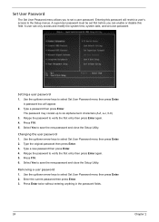
...Press F10. 6. A supervisor password must be set user password. Use the up to select Set User Password menu then press Enter. 2. Select Yes to select Set User Password menu then press Enter. Type the original password then press Enter. 3. The password may consist up /down arrow keys to save the new password and close the Setup Utility. Setting a user password 1. Select Yes to set a user password. Type a password then press Enter. Removing a user password 1. Set User Password The Set User Password menu allows you can enable or disable this password will appear...
...Press F10. 6. A supervisor password must be set user password. Use the up to select Set User Password menu then press Enter. 2. Select Yes to select Set User Password menu then press Enter. Type the original password then press Enter. 3. The password may consist up /down arrow keys to save the new password and close the Setup Utility. Setting a user password 1. Select Yes to set a user password. Type a password then press Enter. Removing a user password 1. Set User Password The Set User Password menu allows you can enable or disable this password will appear...
Service Guide
Page 37
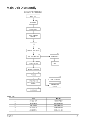
Main Unit Disassembly MAIN UNIT DISASSEMBLY MAIN UNIT Ax2 SIDE PANEL FRONT BEZEL HEAT SINK FAN ASSEMBLY CPU Bx1 OPTICAL DISK DRIVE Cx1 HDD-ODD BRACKET Ax3 Cx1 POWER SUPPLY Dx4 HDD MODULE HDD MEMORY MODULES Ex1 PCI CARD Dx2 FRONT I/O AND CARD READER BOARD BRACKET Cx6 MAINBOARD Cx2 FRONT I/O BOARD Cx2 CARD READER BOARD Screw List A B C D E Chapter 3 Screw #6-32 L5 BZN M3xL5 BZN #6-32 L6 NI #6-32*3/16 NI #6-32 5MM NI Part No. 86.00J07.B60 86.1A324.5R0 86.00J44.C60 86.5A5B6.012 86.9A5G6.162 29
Main Unit Disassembly MAIN UNIT DISASSEMBLY MAIN UNIT Ax2 SIDE PANEL FRONT BEZEL HEAT SINK FAN ASSEMBLY CPU Bx1 OPTICAL DISK DRIVE Cx1 HDD-ODD BRACKET Ax3 Cx1 POWER SUPPLY Dx4 HDD MODULE HDD MEMORY MODULES Ex1 PCI CARD Dx2 FRONT I/O AND CARD READER BOARD BRACKET Cx6 MAINBOARD Cx2 FRONT I/O BOARD Cx2 CARD READER BOARD Screw List A B C D E Chapter 3 Screw #6-32 L5 BZN M3xL5 BZN #6-32 L6 NI #6-32*3/16 NI #6-32 5MM NI Part No. 86.00J07.B60 86.1A324.5R0 86.00J44.C60 86.5A5B6.012 86.9A5G6.162 29
Service Guide
Page 55
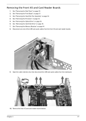
... of the USB and audio cables from the mainboard. 10. Remove the front I /O and Card Reader Boards 1. Chapter 3 47 See "Removing the Processor" on page 36. 6. See "Removing the Optical Drive" on page 34. 5. See "Removing the Memory Modules" on page 38. 7. Open the cable retention clip, then disconnect the USB and audio cables from the front I/O and card reader boards. 9. See "Removing the Hard Disk Drive" on page 44. 8. See "Removing the Heat Sink Fan Assembly" on...
... of the USB and audio cables from the mainboard. 10. Remove the front I /O and Card Reader Boards 1. Chapter 3 47 See "Removing the Processor" on page 36. 6. See "Removing the Optical Drive" on page 34. 5. See "Removing the Memory Modules" on page 38. 7. Open the cable retention clip, then disconnect the USB and audio cables from the front I/O and card reader boards. 9. See "Removing the Hard Disk Drive" on page 44. 8. See "Removing the Heat Sink Fan Assembly" on...
Service Guide
Page 61
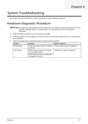
... failure by running the diagnostic tests or repeating the same operation. 3. No beep or error codes issued. Verify the symptoms by attempting to perform. "POST Error Codes" on screen. POST detects an error and displayed messages on page 56. System Troubleshooting Chapter 4 This chapter provides instructions on how to troubleshoot system hardware problems. Hardware Diagnostic Procedure IMPORTANT:The diagnostic tests described in as much detail as possible. 2. Problem Symptom Section to Refer to Power failure...
... failure by running the diagnostic tests or repeating the same operation. 3. No beep or error codes issued. Verify the symptoms by attempting to perform. "POST Error Codes" on screen. POST detects an error and displayed messages on page 56. System Troubleshooting Chapter 4 This chapter provides instructions on how to troubleshoot system hardware problems. Hardware Diagnostic Procedure IMPORTANT:The diagnostic tests described in as much detail as possible. 2. Problem Symptom Section to Refer to Power failure...
Service Guide
Page 62
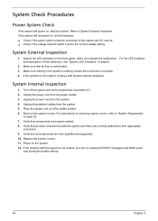
... POST messages and BIOS event logs during the system startup. 54 Chapter 4 Make sure nothing in the system is not evident, continue with the system is not blocked. 3. If the problem with System Internal Inspection. Turn off the system and all cable connectors inside the system are Acer-qualified and supported. 10. Make sure that all the peripherals connected to System External Inspection. Unplug...
... POST messages and BIOS event logs during the system startup. 54 Chapter 4 Make sure nothing in the system is not evident, continue with the system is not blocked. 3. If the problem with System Internal Inspection. Turn off the system and all cable connectors inside the system are Acer-qualified and supported. 10. Make sure that all the peripherals connected to System External Inspection. Unplug...
Service Guide
Page 64
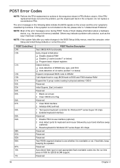
... to E000 and F000 shadow RAM Expand the X group codes locating in the BIOS Setup Utility menus, reset the computer, enter Setup and install Setup defaults or correct the error. NOTE: If the system fails after you make changes in physical address 1000:0 Reserved Initial Superio_Earl_Init switch Reserved 1 Blank out screen 2 Clear CMOS error flag Reserved 1 Clear 8042 interface 2 Initialize 8042 self-test 1 Test special keyboard controller for Winbond 977 series Super I /O chops Reserved Reserved Reserved...
... to E000 and F000 shadow RAM Expand the X group codes locating in the BIOS Setup Utility menus, reset the computer, enter Setup and install Setup defaults or correct the error. NOTE: If the system fails after you make changes in physical address 1000:0 Reserved Initial Superio_Earl_Init switch Reserved 1 Blank out screen 2 Clear CMOS error flag Reserved 1 Clear 8042 interface 2 Initialize 8042 self-test 1 Test special keyboard controller for Winbond 977 series Super I /O chops Reserved Reserved Reserved...
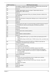
Service Guide
Page 65
... Invoke Video BIOS Reserved Chapter 4 57 Chipset default values are directed to SPURIOUS_INT_HDLR & S/W interrupts to SPURIOUS_soft_HDLR. Prepare BIOS resource map for override. Disable respective clock resource to empty PCI & DIMM slots. 2 Init onboard PWM 3 Init onboard H/W monitor devices Initialize INT 09 buffer Reserved 1 Program CPU internal MTRR (P6 & PII) for 0-640K memory address. 2 Initialize the APIC for RTC minute. 2 Load CMOS settings into chipset...
... Invoke Video BIOS Reserved Chapter 4 57 Chipset default values are directed to SPURIOUS_INT_HDLR & S/W interrupts to SPURIOUS_soft_HDLR. Prepare BIOS resource map for override. Disable respective clock resource to empty PCI & DIMM slots. 2 Init onboard PWM 3 Init onboard H/W monitor devices Initialize INT 09 buffer Reserved 1 Program CPU internal MTRR (P6 & PII) for 0-640K memory address. 2 Initialize the APIC for RTC minute. 2 Load CMOS settings into chipset...
Service Guide
Page 67
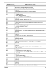
... to every ISA PnP device Reserved Initialize the combined Trend Anti-Virus code Reserved (Optional Feature) Show message for function call: INT 15h ax=E820h Reserved Turn on L2 cache Reserved Program chipset registers according to items described in Setup & Autoconfiguration table. not until this POST stage can users enter the CMOS setup utility. i.e. Reserved Reserved Reset keyboard if Early_Reset_KB is set to enter Setup utility;
... to every ISA PnP device Reserved Initialize the combined Trend Anti-Virus code Reserved (Optional Feature) Show message for function call: INT 15h ax=E820h Reserved Turn on L2 cache Reserved Program chipset registers according to items described in Setup & Autoconfiguration table. not until this POST stage can users enter the CMOS setup utility. i.e. Reserved Reserved Reset keyboard if Early_Reset_KB is set to enter Setup utility;
Service Guide
Page 68
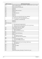
... used by EPA logo (not for full screen logo) 3 If password is set, ask for password Save all PCI ROMs (except VGA) Reserved 1 Enable/Disable Parity Check according to CMOS setup 2 APM Initialization Reserved Clear noise of the memory Reserved 1 Invoke all ISA adapter ROMs 2 Invoke all data in floppy drive. -ALT+F2 is found in stack back to CMOS Initialize ISA PnP boot devices 1 USB final Initialization 2 Switch screen back to text mode...
... used by EPA logo (not for full screen logo) 3 If password is set, ask for password Save all PCI ROMs (except VGA) Reserved 1 Enable/Disable Parity Check according to CMOS setup 2 APM Initialization Reserved Clear noise of the memory Reserved 1 Invoke all ISA adapter ROMs 2 Invoke all data in floppy drive. -ALT+F2 is found in stack back to CMOS Initialize ISA PnP boot devices 1 USB final Initialization 2 Switch screen back to text mode...
Service Guide
Page 72
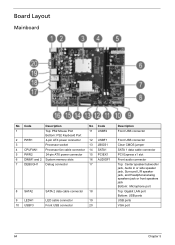
...No Code 1 Top: PS2 Mouse Port 11 USBF2 Bottom: PS2 Keyboard Port 2 PWR1 4-pin ATX power connector 12 USBF1 3 Processor socket 13 JBIOS1 4 CPUFAN1 Processor fan cable connector 14 SATA1 5 PWR2 24-pin ATX power connector 15 PCIEX1 6 DIMM1 and 2 System memory slots 16 AUDIOF1 7 DEBUGH1 Debug connector 17 8 SATA2 9 LEDH1 10 USBF3 SATA 2 data cable connector 18 LED cable connector 19 Front USB connector 20 Description Front USB connector Front USB connector Clear CMOS jumper SATA 1 data cable connector PCI Express x1 slot Front audio connector Top: Center speaker/subwoofer...
...No Code 1 Top: PS2 Mouse Port 11 USBF2 Bottom: PS2 Keyboard Port 2 PWR1 4-pin ATX power connector 12 USBF1 3 Processor socket 13 JBIOS1 4 CPUFAN1 Processor fan cable connector 14 SATA1 5 PWR2 24-pin ATX power connector 15 PCIEX1 6 DIMM1 and 2 System memory slots 16 AUDIOF1 7 DEBUGH1 Debug connector 17 8 SATA2 9 LEDH1 10 USBF3 SATA 2 data cable connector 18 LED cable connector 19 Front USB connector 20 Description Front USB connector Front USB connector Clear CMOS jumper SATA 1 data cable connector PCI Express x1 slot Front audio connector Top: Center speaker/subwoofer...


