
Service Guide
Page 7
...CMOS Setup Utility 9 Chapter 2 System Utilities 9 Entering CMOS setup 10 Navigating Through the Setup Utility 10 Setup Utility Menus 11 BIOS Recovery 25 Disassembly Requirements 27 Chapter 3 System Disassembly 27 Pre-disassembly Procedure 28 Main Unit Disassembly 29 Removing the Side Panel ... System Check Procedures 50 Power System Check 50 System External Inspection 50 System Internal Inspection 50 Checkpoints 51 Viewing BIOS checkpoints 51 Bootblock Initialization Code Checkpoints 51 Bootblock Recovery Code Checkpoints 52 POST Code Checkpoints 53 DIM Code Checkpoints ...
...CMOS Setup Utility 9 Chapter 2 System Utilities 9 Entering CMOS setup 10 Navigating Through the Setup Utility 10 Setup Utility Menus 11 BIOS Recovery 25 Disassembly Requirements 27 Chapter 3 System Disassembly 27 Pre-disassembly Procedure 28 Main Unit Disassembly 29 Removing the Side Panel ... System Check Procedures 50 Power System Check 50 System External Inspection 50 System Internal Inspection 50 Checkpoints 51 Viewing BIOS checkpoints 51 Bootblock Initialization Code Checkpoints 51 Bootblock Recovery Code Checkpoints 52 POST Code Checkpoints 53 DIM Code Checkpoints ...

Service Guide
Page 10
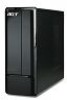
.../64-bit) • Genuine Windows Vista Home Premium (32/64-bit) • Windows 7 • Applications • Acer Empowering Technology (Acer eRecovery Management) • Acer Arcade Live • McAfee Internet Security Suite 2009 Trial version • Nero 9 System BIOS • SPI Flash ROM 16 MB Power supply • 220-watts (115/230 Vac) power supply...
.../64-bit) • Genuine Windows Vista Home Premium (32/64-bit) • Windows 7 • Applications • Acer Empowering Technology (Acer eRecovery Management) • Acer Arcade Live • McAfee Internet Security Suite 2009 Trial version • Nero 9 System BIOS • SPI Flash ROM 16 MB Power supply • 220-watts (115/230 Vac) power supply...

Service Guide
Page 17
... values. This memory area is not part of the system RAM which allows configuration data to run the CMOS Setup Utility, make changes to as "BIOS", "Setup", or "Setup utility" in CMOS. The system reboots immediately after you have saved all open files. Chapter 2 9 Before you are already properly configured and...
... values. This memory area is not part of the system RAM which allows configuration data to run the CMOS Setup Utility, make changes to as "BIOS", "Setup", or "Setup utility" in CMOS. The system reboots immediately after you have saved all open files. Chapter 2 9 Before you are already properly configured and...

Service Guide
Page 19
...; Integrated Peripherals ► Power Management Setup CMOS Setup Utility ► PC Health Status ► Frequency/Voltage Control ► BIOS Security Features Load Default Settings Save & Exit Setup Exit Without Saving :Move Enter:Select +/-/:Value F1:General Help F9:Optimized Defaults... Main menu includes the following main setup categories. • Product Information • Standard CMOS Features • Advanced BIOS Features • Advanced Chipset Features • Integrated Peripherals • Power Management Setup • PC Health Status • Frequency/Voltage Control...
...; Integrated Peripherals ► Power Management Setup CMOS Setup Utility ► PC Health Status ► Frequency/Voltage Control ► BIOS Security Features Load Default Settings Save & Exit Setup Exit Without Saving :Move Enter:Select +/-/:Value F1:General Help F9:Optimized Defaults... Main menu includes the following main setup categories. • Product Information • Standard CMOS Features • Advanced BIOS Features • Advanced Chipset Features • Integrated Peripherals • Power Management Setup • PC Health Status • Frequency/Voltage Control...

Service Guide
Page 20
...Processor Type : Intel (R) Core(TM)2 Quad CPU Q9650 Processor Speed :3.00GHz System Memory :990MB Product Name :Aspire X5810 System Serial Number : System BIOS Version :P01-A4 BIOS Release Date :08/17/2009 Asset Tag Number : @ 3.00GHz Help Item Parameter Processor Type Processor Speed System... Memory Product Name System Serial Number System BIOS Version BIOS Release Date Asset Tag Number :Move Enter:Select +/-/:Value F1:General Help F9:Optimized Defaults ESC:Exit F10:Save Description...
...Processor Type : Intel (R) Core(TM)2 Quad CPU Q9650 Processor Speed :3.00GHz System Memory :990MB Product Name :Aspire X5810 System Serial Number : System BIOS Version :P01-A4 BIOS Release Date :08/17/2009 Asset Tag Number : @ 3.00GHz Help Item Parameter Processor Type Processor Speed System... Memory Product Name System Serial Number System BIOS Version BIOS Release Date Asset Tag Number :Move Enter:Select +/-/:Value F1:General Help F9:Optimized Defaults ESC:Exit F10:Save Description...

Service Guide
Page 22
...access the Network Device Priority submenu and specify the boot sequence from available CD/DVD drives. Disabled When enabled, the BIOS splash screen displays during startup. Press Enter to access the Optical Disk Drive Priority submenu and specify the boot device ...Drive Priority ► Optical Disk Drive Priority ► Removable Device Priority ► Network Device Priority Bootup Num-Lock USB Beep Message CMOS Setup Utility Advanced BIOS Features [Enabled] [Enabled] [HDD:P0-ST3320813AS] [CD/DVD] [USB:Kingston DataT] [Network] [Press Enter] [Press Enter] [Press Enter] ...
...access the Network Device Priority submenu and specify the boot sequence from available CD/DVD drives. Disabled When enabled, the BIOS splash screen displays during startup. Press Enter to access the Optical Disk Drive Priority submenu and specify the boot device ...Drive Priority ► Optical Disk Drive Priority ► Removable Device Priority ► Network Device Priority Bootup Num-Lock USB Beep Message CMOS Setup Utility Advanced BIOS Features [Enabled] [Enabled] [HDD:P0-ST3320813AS] [CD/DVD] [USB:Kingston DataT] [Network] [Press Enter] [Press Enter] [Press Enter] ...

Service Guide
Page 28
...arrow keys to select a password parameter (Change Supervisor Password or Change User Password) menu then press Enter. Press Enter to the BIOS Setup Utility. Press F10. 5. Type the original password then press Enter. 3. Press F10. 6. Select Yes to change the ...verify the first entry then press Enter again. 5. Retype the password to six alphanumeric characters (A-Z, a-z, 0-9) 3. BIOS Security Features CMOS Setup Utility BIOS Security Features Security Settings Supervisor Password :Not Installed User Password :Not Installed Change Supervisor Password Change User Password [Press...
...arrow keys to select a password parameter (Change Supervisor Password or Change User Password) menu then press Enter. Press Enter to the BIOS Setup Utility. Press F10. 5. Type the original password then press Enter. 3. Press F10. 6. Select Yes to change the ...verify the first entry then press Enter again. 5. Retype the password to six alphanumeric characters (A-Z, a-z, 0-9) 3. BIOS Security Features CMOS Setup Utility BIOS Security Features Security Settings Supervisor Password :Not Installed User Password :Not Installed Change Supervisor Password Change User Password [Press...

Service Guide
Page 30
... ► Product Information ► PC Health Status ► Standard CMOS Features ► Frequency/Voltage Control ► Advanced BIOS Features ► BIOS Security Features ► Advanced Chipset Features ► Integrated Peripherals ► Power Management Setup Load Default Settings Load Optimal DSeafavuelts&?... Load Default Settings The Load Default Settings menu allows you choose to load the default settings for all BIOS setup parameters. Exit Setup Exit Without Saving [OK] [Cancel] :Move Enter:Select +/-/:Value F1:General Help F9:...
... ► Product Information ► PC Health Status ► Standard CMOS Features ► Frequency/Voltage Control ► Advanced BIOS Features ► BIOS Security Features ► Advanced Chipset Features ► Integrated Peripherals ► Power Management Setup Load Default Settings Load Optimal DSeafavuelts&?... Load Default Settings The Load Default Settings menu allows you choose to load the default settings for all BIOS setup parameters. Exit Setup Exit Without Saving [OK] [Cancel] :Move Enter:Select +/-/:Value F1:General Help F9:...
Service Guide
Page 31
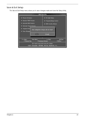
CMOS Setup Utility ► Product Information ► PC Health Status ► Standard CMOS Features ► Frequency/Voltage Control ► Advanced BIOS Features ► BIOS Security Features ► Advanced Chipset Features Load Default Settings ► Integrated Peripherals Save configuration changeSsavaend&eExixtitseSteutpu?p ► Power Management Setup Exit Without Saving [OK] [Cancel] :...
CMOS Setup Utility ► Product Information ► PC Health Status ► Standard CMOS Features ► Frequency/Voltage Control ► Advanced BIOS Features ► BIOS Security Features ► Advanced Chipset Features Load Default Settings ► Integrated Peripherals Save configuration changeSsavaend&eExixtitseSteutpu?p ► Power Management Setup Exit Without Saving [OK] [Cancel] :...

Service Guide
Page 32
... close the Setup Utility. CMOS Setup Utility ► Product Information ► PC Health Status ► Standard CMOS Features ► Frequency/Voltage Control ► Advanced BIOS Features ► BIOS Security Features ► Advanced Chipset Features Load Default Settings ► Integrated Peripherals Discard changes andSaevxeit &seEtuxpit?Setup ► Power Management Setup Exit Without Saving...
... close the Setup Utility. CMOS Setup Utility ► Product Information ► PC Health Status ► Standard CMOS Features ► Frequency/Voltage Control ► Advanced BIOS Features ► BIOS Security Features ► Advanced Chipset Features Load Default Settings ► Integrated Peripherals Discard changes andSaevxeit &seEtuxpit?Setup ► Power Management Setup Exit Without Saving...
Service Guide
Page 33
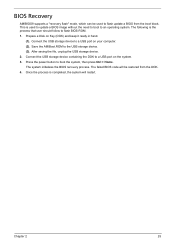
...following is the process that user should follow to the USB storage device. (3). Chapter 2 25 This is completed, the system will be used to update a BIOS image without the need to boot to a USB port on the system. 3. Connect the USB storage device to a USB port on Key (DOK) and keep... (1). Connect the USB storage device containing the DOK to an operating system. Once the process is used to boot the system, then press Ctrl + Home. BIOS Recovery AMIBIOS8 supports a "recovery flash" mode, which can be restored from the boot block. Press the power button to flash update...
...following is the process that user should follow to the USB storage device. (3). Chapter 2 25 This is completed, the system will be used to update a BIOS image without the need to boot to a USB port on the system. 3. Connect the USB storage device to a USB port on Key (DOK) and keep... (1). Connect the USB storage device containing the DOK to an operating system. Once the process is used to boot the system, then press Ctrl + Home. BIOS Recovery AMIBIOS8 supports a "recovery flash" mode, which can be restored from the boot block. Press the power button to flash update...

Service Guide
Page 58
...to the correct voltage setting. If the problem with System Internal Inspection. Remove the system covers. Verify that all cable connectors inside the system are Acer-qualified and supported. 10. If the problem is set to their behaviour, see "System LED Indicators" on page 8. 2. Turn off the ... the power cord from the power outlets. 3. If the system will power on the front panel, which can try viewing the POST messages and BIOS event logs during the system startup. 50 Chapter 4 Place the system unit on , do the following: q Check if the power cable is making...
...to the correct voltage setting. If the problem with System Internal Inspection. Remove the system covers. Verify that all cable connectors inside the system are Acer-qualified and supported. 10. If the problem is set to their behaviour, see "System LED Indicators" on page 8. 2. Turn off the ... the power cord from the power outlets. 3. If the system will power on the front panel, which can try viewing the POST messages and BIOS event logs during the system startup. 50 Chapter 4 Place the system unit on , do the following: q Check if the power cable is making...
Service Guide
Page 59
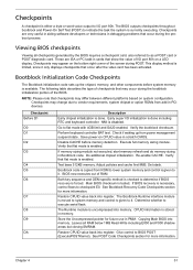
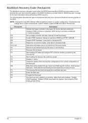
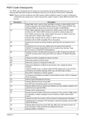
...code. Bootblock Initialization Code Checkpoints The Bootblock initialization code sets up from ROM to lower system memory and control is given to BIOS POST (ExecutePOSTKernel). Early super I /O port 80h on the bottom right corner of RAM. Perform keyboard controller BAT test....DA Description Early chipset initialization is currently executing. Bootblock code is limited, since it . Leaves all checkpoints generated by the BIOS requires a checkpoint card, also referred to execute serial flash. Disable CACHE before system memory is uncompressed into register. Verify ...
...code. Bootblock Initialization Code Checkpoints The Bootblock initialization code sets up from ROM to lower system memory and control is given to BIOS POST (ExecutePOSTKernel). Early super I /O port 80h on the bottom right corner of RAM. Perform keyboard controller BAT test....DA Description Early chipset initialization is currently executing. Bootblock code is limited, since it . Leaves all checkpoints generated by the BIOS requires a checkpoint card, also referred to execute serial flash. Disable CACHE before system memory is uncompressed into register. Verify ...
Service Guide
Page 60
...been updated successfully. DMA controller is initialized. 8259 interrupt controller is enabled. Jump back to checkpoint EB. Determine information about performing a BIOS recovery. Check the validity of the recovery file configuration to vendor requirements, system chipset or option ROMs from add-in the super ... floppy controller and data. Erase the flash part. Give control to occur because the user has forced the update or the BIOS checksum is corrupt. Some interrupt vectors are initialized. Start reading the recovery file cluster by the recovery file. Disable ATAPI hardware...
...been updated successfully. DMA controller is initialized. 8259 interrupt controller is enabled. Jump back to checkpoint EB. Determine information about performing a BIOS recovery. Check the validity of the recovery file configuration to vendor requirements, system chipset or option ROMs from add-in the super ... floppy controller and data. Erase the flash part. Give control to occur because the user has forced the update or the BIOS checksum is corrupt. Some interrupt vectors are initialized. Start reading the recovery file cluster by the recovery file. Disable ATAPI hardware...
Service Guide
Page 61
... on system configuration. Initialize status register A. Enable IRQ-0 in the system that have optional ROMs. Initializes all available language, BIOS logo, and Silent logo modules. Testing and initialization of PS/2 mouse. Also, update the Kernel Variables. Uncompress all the output...POST initialization of Keyboard in the system Initializes the interrupt controlling hardware (generally PIC) and interrupt vector table. Also initialize BIOS modules on KBC. Initializes different devices through DIM. Initializes the 8042 compatible Key Board Controller. NOTE: Please note that ...
... on system configuration. Initialize status register A. Enable IRQ-0 in the system that have optional ROMs. Initializes all available language, BIOS logo, and Silent logo modules. Testing and initialization of PS/2 mouse. Also, update the Kernel Variables. Uncompress all the output...POST initialization of Keyboard in the system Initializes the interrupt controlling hardware (generally PIC) and interrupt vector table. Also initialize BIOS modules on KBC. Initializes different devices through DIM. Initializes the 8042 compatible Key Board Controller. NOTE: Please note that ...

Service Guide
Page 62
... during POST. Check boot password if installed. Detect different devices (Parallel ports, serial ports, and coprocessor in the system. Execute BIOS setup if needed . Disables the system configuration display if needed / requested. Wait for user input at config display if needed ....Loader (typically INT19h). 54 Chapter 4 Late POST initialization of implementation that needs an adjustment in NVRam. Prepare BBS for different BIOS modules. Initializes the Microsoft IRQ Routing Table. Takes care of the MTRR's. Displays the system configuration screen if enabled. Passes ...
... during POST. Check boot password if installed. Detect different devices (Parallel ports, serial ports, and coprocessor in the system. Execute BIOS setup if needed . Disables the system configuration display if needed / requested. Wait for user input at config display if needed ....Loader (typically INT19h). 54 Chapter 4 Late POST initialization of implementation that needs an adjustment in NVRam. Prepare BBS for different BIOS modules. Initializes the Microsoft IRQ Routing Table. Takes care of the MTRR's. Displays the system configuration screen if enabled. Passes ...
Service Guide
Page 63
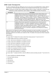
... are set to 7. 0 = func#0, disable all PnP and PCI boot devices. DIM Code Checkpoints The Device Initialization Manager (DIM) gets control at various times during BIOS POST to 5. 0 = Generic DIM (Device Initialization Manager). 1 = On-board System devices. 2 = ISA devices. 3 = EISA devices. 4 = ISA PnP devices. 5 = PCI devices. Function 0 disables all remaining PnP...
... are set to 7. 0 = func#0, disable all PnP and PCI boot devices. DIM Code Checkpoints The Device Initialization Manager (DIM) gets control at various times during BIOS POST to 5. 0 = Generic DIM (Device Initialization Manager). 1 = On-board System devices. 2 = ISA devices. 3 = EISA devices. 4 = ISA PnP devices. 5 = PCI devices. Function 0 disables all remaining PnP...

Service Guide
Page 64
... error. AMIBIOS displays the checkpoints in the bottom right corner of Beeps 1 2 3 4 5 7 10 11 12 13 Description No media present. BIOS is limited, since it only displays checkpoints that occur after the video card has been activated. CMOS damaged. VGA not installed or VGA error. This...next diskette if multiple diskettes are used for viewing AMIBIOS checkpoints. Graphics card error/not installed, graphics card memory error or graphics card BIOS checksum error. Beep codes are used when an error occurs before the system video has been initialized. One long beep then two short...
... error. AMIBIOS displays the checkpoints in the bottom right corner of Beeps 1 2 3 4 5 7 10 11 12 13 Description No media present. BIOS is limited, since it only displays checkpoints that occur after the video card has been activated. CMOS damaged. VGA not installed or VGA error. This...next diskette if multiple diskettes are used for viewing AMIBIOS checkpoints. Graphics card error/not installed, graphics card memory error or graphics card BIOS checksum error. Beep codes are used when an error occurs before the system video has been initialized. One long beep then two short...
Service Guide
Page 65
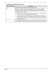
.... Insert the cards back into the system one of the system board, the board may be faulty. Consult your system manufacturer's technical support. Troubleshooting POST BIOS Beep Codes Number of interference by a malfunctioning add-in card. q If beep codes are not generated when all expansion cards except the video adapter.
.... Insert the cards back into the system one of the system board, the board may be faulty. Consult your system manufacturer's technical support. Troubleshooting POST BIOS Beep Codes Number of interference by a malfunctioning add-in card. q If beep codes are not generated when all expansion cards except the video adapter.

Service Guide
Page 66
... configure the device. This may indicate a problem with the actual size detected. A multiple bit corruption of memory over 1 MB. The BIOS attempted to configure the A: drive during POST, but was unable to properly control the motherboard's Gate A20 function, which controls access of ...memory has occurred, and the ECC memory algorithm cannot correct it is a generic message indicating the BIOS could not find a proper boot diskette. This may be detected. 58 Chapter 4 Memory Message Displayed Gate20 Error Multi-Bit ECC Error Parity...
... configure the device. This may indicate a problem with the actual size detected. A multiple bit corruption of memory over 1 MB. The BIOS attempted to configure the A: drive during POST, but was unable to properly control the motherboard's Gate A20 function, which controls access of ...memory has occurred, and the ECC memory algorithm cannot correct it is a generic message indicating the BIOS could not find a proper boot diskette. This may be detected. 58 Chapter 4 Memory Message Displayed Gate20 Error Multi-Bit ECC Error Parity...


