
Acer Aspire X1935 Desktop Service Guide
Page 6
... personnel/channel to order FRU parts for repair and service of this generic service guide. If, for Acer's "global" product offering. For ACER-AUTHORIZED SERVICE PROVIDERS, your Acer office may have decided to those given in the printed Service Guide. You MUST use the list provided... by your regional Acer office to provide you with all technical information relating to -date information available on card, modem, or extra memory capability). vi FRU Information Please note WHEN ORDERING FRU PARTS, that you ...
... personnel/channel to order FRU parts for repair and service of this generic service guide. If, for Acer's "global" product offering. For ACER-AUTHORIZED SERVICE PROVIDERS, your Acer office may have decided to those given in the printed Service Guide. You MUST use the list provided... by your regional Acer office to provide you with all technical information relating to -date information available on card, modem, or extra memory capability). vi FRU Information Please note WHEN ORDERING FRU PARTS, that you ...

Acer Aspire X1935 Desktop Service Guide
Page 7
...31 Removing the HDD-ODD Bracket 33 Removing the Optical Drive and Hard Disk Drive 34 Detaching the Front Bezel 38 Removing the Memory Modules 39 Removing the Power Supply 40 Removing the Front I/O and Optional Card Reader Assembly 42 Removing the Mainboard 45 Assembly Requirements...Removing the HDD-ODD Bracket 51 Reinstalling the I/O Shielding 52 Reinstalling the Main Board 53 Reinstalling the Power Supply 55 Reinstalling the Memory 57 Reinstalling the Front Bezel Power Button/LED Cable 58 Reinstalling the Optical Drive and Hard Disk Drive 59 Reinstalling the HDD-ODD...
...31 Removing the HDD-ODD Bracket 33 Removing the Optical Drive and Hard Disk Drive 34 Detaching the Front Bezel 38 Removing the Memory Modules 39 Removing the Power Supply 40 Removing the Front I/O and Optional Card Reader Assembly 42 Removing the Mainboard 45 Assembly Requirements...Removing the HDD-ODD Bracket 51 Reinstalling the I/O Shielding 52 Reinstalling the Main Board 53 Reinstalling the Power Supply 55 Reinstalling the Memory 57 Reinstalling the Front Bezel Power Button/LED Cable 58 Reinstalling the Optical Drive and Hard Disk Drive 59 Reinstalling the HDD-ODD...

Acer Aspire X1935 Desktop Service Guide
Page 9
... Bridge Processor. • Socket type: LGA1155. • FMB: 65W / 95W. Chapter 1 1 Chipset • PCH: Intel B75 PCB • DTX, max 4 Layers Memory subsystem • Socket Type: DDR III connector. • Socket Quantity: 4 DIMMs. • 2 channels, 2 DIMMs per channel. VRD power • Dual Output 4 (3+4)...in this section is a brief summary of the computer's many feature: NOTE: The features listed in 2 same memory size DDRIII. memory module. • Max memory of the system depends on the model purchased. The exact configuration of 16 GB supported (using 4Gb tech). &#...
... Bridge Processor. • Socket type: LGA1155. • FMB: 65W / 95W. Chapter 1 1 Chipset • PCH: Intel B75 PCB • DTX, max 4 Layers Memory subsystem • Socket Type: DDR III connector. • Socket Quantity: 4 DIMMs. • 2 channels, 2 DIMMs per channel. VRD power • Dual Output 4 (3+4)...in this section is a brief summary of the computer's many feature: NOTE: The features listed in 2 same memory size DDRIII. memory module. • Max memory of the system depends on the model purchased. The exact configuration of 16 GB supported (using 4Gb tech). &#...

Acer Aspire X1935 Desktop Service Guide
Page 14
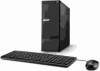
Front Panel No. Component 1 Power button/indicator 2 Optical drive cover 3 Optical drive eject button 4 Headphone jack 5 Microphone-in jack 6 4-in-1 optional card reader supporting Memory Stick (MS), xD-Picture Card (xD), Secure Digital (SD), MultiMediaCard (MMC) and Memory Stick PRO (MS PRO) 7 USB 2.0 ports 8 Acer logo 6 Chapter 1 System Components This section is a virtual tour of the system's interior and exterior components.
Front Panel No. Component 1 Power button/indicator 2 Optical drive cover 3 Optical drive eject button 4 Headphone jack 5 Microphone-in jack 6 4-in-1 optional card reader supporting Memory Stick (MS), xD-Picture Card (xD), Secure Digital (SD), MultiMediaCard (MMC) and Memory Stick PRO (MS PRO) 7 USB 2.0 ports 8 Acer logo 6 Chapter 1 System Components This section is a virtual tour of the system's interior and exterior components.

Acer Aspire X1935 Desktop Service Guide
Page 17
... System Memory Supported Total Memory 1G ~4GB 1G ~4GB 1G ~4GB 1G ~4GB 1G~16GB System Memory Item Specification Memory slot number 4 slot Support Memory size per socket 1GB/2GB/4GB Support memory type DDRIII Support memory interface DDRIII 1333/1600MHz Support memory voltage 1.5V Support memory module ...-pin DDRIII Support to parity check feature Yes Support to error correction code (ECC) feature No Memory module combinations You can install memory modules in any other HDA compatible audio controller. Audio Interface Item Specification Audio controller Intel PCH B75...
... System Memory Supported Total Memory 1G ~4GB 1G ~4GB 1G ~4GB 1G ~4GB 1G~16GB System Memory Item Specification Memory slot number 4 slot Support Memory size per socket 1GB/2GB/4GB Support memory type DDRIII Support memory interface DDRIII 1333/1600MHz Support memory voltage 1.5V Support memory module ...-pin DDRIII Support to parity check feature Yes Support to error correction code (ECC) feature No Memory module combinations You can install memory modules in any other HDA compatible audio controller. Audio Interface Item Specification Audio controller Intel PCH B75...

Acer Aspire X1935 Desktop Service Guide
Page 21
...turned off. CMOS setup loads the configuration values in this guide display default system values. The screenshots used in a battery-backed nonvolatile memory called the complementary metaloxide semiconductor (CMOS) Setup Utility. These values may be bad. Ask a qualified technician for assistance. Before you ...the system RAM which allows configuration data to as "BIOS", "Setup", or "Setup utility" in this utility. Chapter 2 13 This memory area is no need to run this guide. The system reboots immediately after you have saved all open files. NOTE: CMOS Setup Utility...
...turned off. CMOS setup loads the configuration values in this guide display default system values. The screenshots used in a battery-backed nonvolatile memory called the complementary metaloxide semiconductor (CMOS) Setup Utility. These values may be bad. Ask a qualified technician for assistance. Before you ...the system RAM which allows configuration data to as "BIOS", "Setup", or "Setup utility" in this utility. Chapter 2 13 This memory area is no need to run this guide. The system reboots immediately after you have saved all open files. NOTE: CMOS Setup Utility...

Acer Aspire X1935 Desktop Service Guide
Page 23
Date when the BIOS setup utility was built Type of system memory installed on the system. In the descriptive table following the hour-minute-second format. Asset tag number of the system. Chapter 2 15 Physical CPU count ... time following each of the CPU installed on the system. Product name of this system. Parameter System BIOS Version Build Date Processor Core Frequency Count Memory Size Product Name System Serial Number Asset Tag Number System Date System Time (hh:mm:ss) Description Version number of the system. Serial number of...
Date when the BIOS setup utility was built Type of system memory installed on the system. In the descriptive table following the hour-minute-second format. Asset tag number of the system. Chapter 2 15 Physical CPU count ... time following each of the CPU installed on the system. Product name of this system. Parameter System BIOS Version Build Date Processor Core Frequency Count Memory Size Product Name System Serial Number Asset Tag Number System Date System Time (hh:mm:ss) Description Version number of the system. Serial number of...

Acer Aspire X1935 Desktop Service Guide
Page 47
Please detach the Circuit boards and follow local regulations for disposal. Chapter 3 39 Note:Circuit boards >10 cm² has been highlighted with the yellow rectangle as above image shows. Removing the Memory Modules IMPORTANT:Before removing any DIMM from the M/B(2). Gently pull the DIMM upward to pull it away from the memory board, make sure to create a backup file of the DIMM slot outward to release the DIMM(1). 2. Press the holding clips on both sides of all important data. 1.
Please detach the Circuit boards and follow local regulations for disposal. Chapter 3 39 Note:Circuit boards >10 cm² has been highlighted with the yellow rectangle as above image shows. Removing the Memory Modules IMPORTANT:Before removing any DIMM from the M/B(2). Gently pull the DIMM upward to pull it away from the memory board, make sure to create a backup file of the DIMM slot outward to release the DIMM(1). 2. Press the holding clips on both sides of all important data. 1.

Acer Aspire X1935 Desktop Service Guide
Page 65
Open the holding clips on both sides of the DIMM slot outward. 2. If a second memory module is available, install it clicks into place (2). 3. Reinnstalling the Memory 1. Chapter 3 57 Insert the memory module into the DIMM1 slot (1) and then press it down until it in the DIMM2 slot by repeating step 1.
Open the holding clips on both sides of the DIMM slot outward. 2. If a second memory module is available, install it clicks into place (2). 3. Reinnstalling the Memory 1. Chapter 3 57 Insert the memory module into the DIMM1 slot (1) and then press it down until it in the DIMM2 slot by repeating step 1.
Acer Aspire X1935 Desktop Service Guide
Page 81
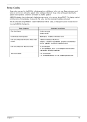
BIOS damaged. Beep codes will be generated by the BIOS to indicate a serious or fatal error to the end user. Memory not installed or memory error. VGA not installed or VGA error. CMOS damaged. Beep codes are used when an error occurs before the system video has ...been initialized. AMIBIOS displays the checkpoints in the bottom right corner of the screen during POST. Graphics card error/not installed, graphics card memory error or graphics card BIOS checksum error. CMOS checksum error or CMOS battery loss occurs. Beep Symptom One short beep Continuous one long beep...
BIOS damaged. Beep codes will be generated by the BIOS to indicate a serious or fatal error to the end user. Memory not installed or memory error. VGA not installed or VGA error. CMOS damaged. Beep codes are used when an error occurs before the system video has ...been initialized. AMIBIOS displays the checkpoints in the bottom right corner of the screen during POST. Graphics card error/not installed, graphics card memory error or graphics card BIOS checksum error. CMOS checksum error or CMOS battery loss occurs. Beep Symptom One short beep Continuous one long beep...

Acer Aspire X1935 Desktop Service Guide
Page 82
...keyboard controller BAT test. Do additional chipset initialization. Bootblock Initialization Code Checkpoints The Bootblock initialization code sets up the chipset,memory, and other CPU critical initialization. Serial port is enabled at this point. The following table describes the type of... RAM. Early Boot Strap Processor (BSP) initialization like microcode update, frequency and other components before memory detection. Execute full memory sizing module. Adjust policies and cache first 8MB. Checkpoint sare very useful in aiding software developers or technicians...
...keyboard controller BAT test. Do additional chipset initialization. Bootblock Initialization Code Checkpoints The Bootblock initialization code sets up the chipset,memory, and other CPU critical initialization. Serial port is enabled at this point. The following table describes the type of... RAM. Early Boot Strap Processor (BSP) initialization like microcode update, frequency and other components before memory detection. Execute full memory sizing module. Adjust policies and cache first 8MB. Checkpoint sare very useful in aiding software developers or technicians...

Acer Aspire X1935 Desktop Service Guide
Page 83
OEM memory detection/configuration error. This range is waking from one platform to BIOS POST (ExecutePOSTKernel). System is reserved for more information. Chapter 4 74 See POST Code Checkpoints section of document for chipset vendors & system manufacturers. Checkpoint DA DC E1-E8 ECEE Description Restore CPUID value back into register. Give control to the next. The error associated with this value may be different from ACPI S3 state.
OEM memory detection/configuration error. This range is waking from one platform to BIOS POST (ExecutePOSTKernel). System is reserved for more information. Chapter 4 74 See POST Code Checkpoints section of document for chipset vendors & system manufacturers. Checkpoint DA DC E1-E8 ECEE Description Restore CPUID value back into register. Give control to the next. The error associated with this value may be different from ACPI S3 state.
Acer Aspire X1935 Desktop Service Guide
Page 97
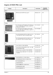
Aspire X1935 FRU List Category MB Kit Description MB Kit aLena Intel B75 Acer Logo LF Part Number Exploded Diagram Item MB.SJL01.001 N/A Chassis Bezel CPU Memory Chapter 6 Hon Hai Chassis xSFF HX097I w/i FIO USB 2 port HS.13100.267 N/A & 5-in-1 CR for Aspire AX152 Bezel, supports I/O shielding (2011 New CI) Hon Hai Chassis xSFF HX097J...
Aspire X1935 FRU List Category MB Kit Description MB Kit aLena Intel B75 Acer Logo LF Part Number Exploded Diagram Item MB.SJL01.001 N/A Chassis Bezel CPU Memory Chapter 6 Hon Hai Chassis xSFF HX097I w/i FIO USB 2 port HS.13100.267 N/A & 5-in-1 CR for Aspire AX152 Bezel, supports I/O shielding (2011 New CI) Hon Hai Chassis xSFF HX097J...
Acer Aspire X1935 Desktop Service Guide
Page 98
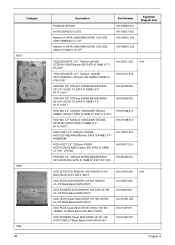
....01605.007 KU.0160D.055 KU.0160F.011 KU.01605.007 Chapter 6 Category HDD ODD VGA 89 Description HU564403EP0200 ACR512X64D3U13C9G Memory A-DATA UNB-DIMM DDRIII 1333 2GB AD63I1B0823EV LF+HF Memory A-DATA UNB-DIMM DDRIII 1333 4GB AD63I1C1624EV LF+HF Part Number KN.4GB0H.001 KN.4GB07.002 KN.2GB0C.009 Exploded...
....01605.007 KU.0160D.055 KU.0160F.011 KU.01605.007 Chapter 6 Category HDD ODD VGA 89 Description HU564403EP0200 ACR512X64D3U13C9G Memory A-DATA UNB-DIMM DDRIII 1333 2GB AD63I1B0823EV LF+HF Memory A-DATA UNB-DIMM DDRIII 1333 4GB AD63I1C1624EV LF+HF Part Number KN.4GB0H.001 KN.4GB07.002 KN.2GB0C.009 Exploded...


