
Acer Aspire X1935 Desktop Service Guide
Page 7
...Diagram 5 System Components 6 Front Panel 6 Rear Panel 7 Hardware Specifications and Configurations 8 Power Management Function(ACPI support function) 12 System Utilities 13 CMOS Setup Utility 13 Entering CMOS setup 14 Navigating Through the Setup Utility 14 Setup Utility Menus 15 Main 15 System Disassembly and Assembly 25 Disassembly Requirements 25 Pre-disassembly Procedure 26 Removing the Side Panel 27 Removing the Front Bezel 28 Removing the Heat Sink Fan Assembly 29 Removing the Processor 31 Removing the HDD-ODD Bracket 33 Removing the Optical Drive...
...Diagram 5 System Components 6 Front Panel 6 Rear Panel 7 Hardware Specifications and Configurations 8 Power Management Function(ACPI support function) 12 System Utilities 13 CMOS Setup Utility 13 Entering CMOS setup 14 Navigating Through the Setup Utility 14 Setup Utility Menus 15 Main 15 System Disassembly and Assembly 25 Disassembly Requirements 25 Pre-disassembly Procedure 26 Removing the Side Panel 27 Removing the Front Bezel 28 Removing the Heat Sink Fan Assembly 29 Removing the Processor 31 Removing the HDD-ODD Bracket 33 Removing the Optical Drive...

Acer Aspire X1935 Desktop Service Guide
Page 8
System Internal Inspection 71 Beep Codes 72 Checkpoints 73 BIOS Recovery 76 Jumper and Connector Information 77 M/B Placement 77 Jumper Setting 79 Internal Header Pin Definition 80 Connector Pin Definition 83 FRU (Field Replaceable Unit) List 86 Aspire X19350 Exploded Diagram 87 Aspire X1935 FRU List 88 viii
System Internal Inspection 71 Beep Codes 72 Checkpoints 73 BIOS Recovery 76 Jumper and Connector Information 77 M/B Placement 77 Jumper Setting 79 Internal Header Pin Definition 80 Connector Pin Definition 83 FRU (Field Replaceable Unit) List 86 Aspire X19350 Exploded Diagram 87 Aspire X1935 FRU List 88 viii
Acer Aspire X1935 Desktop Service Guide
Page 10
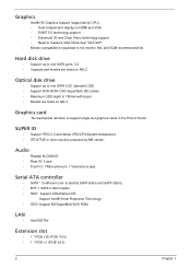
.../SuperMulti/DVD ROM. Serial ATA controller • SATA * 3 (different color to the monitor AVL and DQM recommended list. SUPER IO • Support PECI 3.0 and detect VRD/CPU/System temperature. • ITE 8772E or other solution proposed by CPU). • Dual independent display on AVLC. Graphics card • No mechanical retriction to support single slot graphics cards in , 1*head phone jack. Graphics • Intel® HD Graphics Support (supported by MB vender. Hard disk drive • Support...
.../SuperMulti/DVD ROM. Serial ATA controller • SATA * 3 (different color to the monitor AVL and DQM recommended list. SUPER IO • Support PECI 3.0 and detect VRD/CPU/System temperature. • ITE 8772E or other solution proposed by CPU). • Dual independent display on AVLC. Graphics card • No mechanical retriction to support single slot graphics cards in , 1*head phone jack. Graphics • Intel® HD Graphics Support (supported by MB vender. Hard disk drive • Support...

Acer Aspire X1935 Desktop Service Guide
Page 11
... 3 pin FAN control). Chapter 1 3 Rear I/O connectors • 1 * PS2 KB+MS • 1 * VGA connector • 1 * HDMI • 1 * RJ45 + Dual USB2.0 • 1 * Dual USB2.0 connector • 2 * USB 3.0 stack • 1 * 3 ports Audio jack On-board connectors • 1 * ILM(Independent Loading Mechanism) for LGA 1155 CPU (assign by Acer). • 1 * 24-pin ATX PWR connector. • 1 * H2X4 Power Supply Connector. • 4 * DDR3 DIMM Socket. • 2 * SATA 3Gb/s. • 1 * SATA 6Gb/s. • 2 * USB2.0 H5X2 Header (support 4 ports). • 1 * USB 3.0 H10x2 Header (support 2 ports...
... 3 pin FAN control). Chapter 1 3 Rear I/O connectors • 1 * PS2 KB+MS • 1 * VGA connector • 1 * HDMI • 1 * RJ45 + Dual USB2.0 • 1 * Dual USB2.0 connector • 2 * USB 3.0 stack • 1 * 3 ports Audio jack On-board connectors • 1 * ILM(Independent Loading Mechanism) for LGA 1155 CPU (assign by Acer). • 1 * 24-pin ATX PWR connector. • 1 * H2X4 Power Supply Connector. • 4 * DDR3 DIMM Socket. • 2 * SATA 3Gb/s. • 1 * SATA 6Gb/s. • 2 * USB2.0 H5X2 Header (support 4 ports). • 1 * USB 3.0 H10x2 Header (support 2 ports...

Acer Aspire X1935 Desktop Service Guide
Page 12
• 1 * H3X1 Clear CMOS Header (with Acer skin. System BIOS • Type: • Use SPI Flash. • ME Size: /5MBytes (For B75). • System BIOS: 8MBytes (For B75). • Kernel: • AMI Kernel with jumper). • 1 * onboard Buzzer. • 2 * H1X2 GPIO header. • 1 * H10X2 TPM header. • 1 * 3pin ME enable / disable connector(Jumper). Power supply • Non PFC 220W / PFC 220W / Active PFC 220W. • Support models are listed on AVLC. 4 Chapter 1
• 1 * H3X1 Clear CMOS Header (with Acer skin. System BIOS • Type: • Use SPI Flash. • ME Size: /5MBytes (For B75). • System BIOS: 8MBytes (For B75). • Kernel: • AMI Kernel with jumper). • 1 * onboard Buzzer. • 2 * H1X2 GPIO header. • 1 * H10X2 TPM header. • 1 * 3pin ME enable / disable connector(Jumper). Power supply • Non PFC 220W / PFC 220W / Active PFC 220W. • Support models are listed on AVLC. 4 Chapter 1

Acer Aspire X1935 Desktop Service Guide
Page 16
...LAN controller Intel 82579V SATA controller Intel B75 Super IO controller ITE 8772F 8 Chapter 1 Hardware Specifications and Configurations Processor Item Specification Processor Type Intel Ivy Bridge / Sandy Bridge Processor Socket Type LGA1155 Minimum operating speed 0 MHz (If Stop CPU Clock in Sleep State in BIOS Setup is set to Enabled.) BIOS Item Specification BIOS code programer AMI Kernel with Acer skin BIOS version P01-A0 BIOS ROM type SPI Flash BIOS ROM size 64Mb Support protocol SMBIOS(DMI)2.7 Device Boot Support 1st priority: SATA HDD 2nd priority: CD-ROM...
...LAN controller Intel 82579V SATA controller Intel B75 Super IO controller ITE 8772F 8 Chapter 1 Hardware Specifications and Configurations Processor Item Specification Processor Type Intel Ivy Bridge / Sandy Bridge Processor Socket Type LGA1155 Minimum operating speed 0 MHz (If Stop CPU Clock in Sleep State in BIOS Setup is set to Enabled.) BIOS Item Specification BIOS code programer AMI Kernel with Acer skin BIOS version P01-A0 BIOS ROM type SPI Flash BIOS ROM size 64Mb Support protocol SMBIOS(DMI)2.7 Device Boot Support 1st priority: SATA HDD 2nd priority: CD-ROM...

Acer Aspire X1935 Desktop Service Guide
Page 17
... Memory slot number 4 slot Support Memory size per socket 1GB/2GB/4GB Support memory type DDRIII Support memory interface DDRIII 1333/1600MHz Support memory voltage 1.5V Support memory module package 240-pin DDRIII Support to parity check feature Yes Support to error correction code (ECC) feature No Memory module combinations You can install memory modules in any other HDA compatible audio controller. Audio Interface Item Specification Audio controller Intel PCH B75 Audio controller type ALC662-VD Audio channel codec 5.1 Audio function control Enable/disable by BIOS...
... Memory slot number 4 slot Support Memory size per socket 1GB/2GB/4GB Support memory type DDRIII Support memory interface DDRIII 1333/1600MHz Support memory voltage 1.5V Support memory module package 240-pin DDRIII Support to parity check feature Yes Support to error correction code (ECC) feature No Memory module combinations You can install memory modules in any other HDA compatible audio controller. Audio Interface Item Specification Audio controller Intel PCH B75 Audio controller type ALC662-VD Audio channel codec 5.1 Audio function control Enable/disable by BIOS...

Acer Aspire X1935 Desktop Service Guide
Page 19
... Vibration Operating (unpacked) 5 ~ 500 Hz: 2.20g RMS random, 10 minutes per axis in all 3 axes. 5 ~500 Hz: 1.09g RMS random, 1 hour per axis in all 3 axes. Power Management Devices S1 S3 S4 Power Button V V V USB Keyboard/Mouse V V N/A PME Disabled Disabled Disabled RCT Disabled Disabled Disabled WOR Disabled Disabled Disabled • Devices wake up from S3 should be less than. • Devices wake up from S5 should be less than 10 seconds. S5 V N/A Disabled Disabled Disabled...
... Vibration Operating (unpacked) 5 ~ 500 Hz: 2.20g RMS random, 10 minutes per axis in all 3 axes. 5 ~500 Hz: 1.09g RMS random, 1 hour per axis in all 3 axes. Power Management Devices S1 S3 S4 Power Button V V V USB Keyboard/Mouse V V N/A PME Disabled Disabled Disabled RCT Disabled Disabled Disabled WOR Disabled Disabled Disabled • Devices wake up from S3 should be less than. • Devices wake up from S5 should be less than 10 seconds. S5 V N/A Disabled Disabled Disabled...

Acer Aspire X1935 Desktop Service Guide
Page 20
... in,keyboard an mouse for APM mode. • Resume recovery time :7-10sec Suspend Mode • Independent power management timer(2-120minutes,time step=10minute)or pushing extern switch button. • CPU goes into SMM • CPU asserts STPCLK# and goes into the Stop Grant State. • LED on panel turns amber colour. • Hard disk drive goes into SLEEP mode (for ATA standard interface). • Disable H-sync and V-sync signals to control the...
... in,keyboard an mouse for APM mode. • Resume recovery time :7-10sec Suspend Mode • Independent power management timer(2-120minutes,time step=10minute)or pushing extern switch button. • CPU goes into SMM • CPU asserts STPCLK# and goes into the Stop Grant State. • LED on panel turns amber colour. • Hard disk drive goes into SLEEP mode (for ATA standard interface). • Disable H-sync and V-sync signals to control the...

Acer Aspire X1935 Desktop Service Guide
Page 21
... the communication ports to prevent any conflicts • When modifying the power management configuration • When changing the password or making other changes to the security setup • When a configuration error is detected by the system and you are already properly configured and optimized, there is a hardware configuration program built into the system ROM, called CMOS RAM. Chapter 2 13 In this guide. NOTE: CMOS Setup Utility will need to the CMOS setup NOTE: If...
... the communication ports to prevent any conflicts • When modifying the power management configuration • When changing the password or making other changes to the security setup • When a configuration error is detected by the system and you are already properly configured and optimized, there is a hardware configuration program built into the system ROM, called CMOS RAM. Chapter 2 13 In this guide. NOTE: CMOS Setup Utility will need to the CMOS setup NOTE: If...

Acer Aspire X1935 Desktop Service Guide
Page 23
Date when the BIOS setup utility was built Type of CPU installed on the system. Set the system time following the weekday-month-day-year format. Core speed of the CPU installed on the system. Physical CPU count Total size of the BIOS setup utility. Parameter System BIOS Version Build Date Processor Core Frequency Count Memory Size Product Name System Serial Number Asset Tag Number System Date System Time (hh:mm...
Date when the BIOS setup utility was built Type of CPU installed on the system. Set the system time following the weekday-month-day-year format. Core speed of the CPU installed on the system. Physical CPU count Total size of the BIOS setup utility. Parameter System BIOS Version Build Date Processor Core Frequency Count Memory Size Product Name System Serial Number Asset Tag Number System Date System Time (hh:mm...

Acer Aspire X1935 Desktop Service Guide
Page 27
... Enabled Disabled Enabled Disabled Auto Floppy Hard Disk Enabled Disabled Enabled Disabled Enabled Disabled Enabled Disabled Chapter 2 19 If Auto, USB device equal or less than 2GB will be used to force a HDD formatted drive to boot as harddrive. Select an operating mode for onboard network controller. Enables or disables the onboard USB controller. Enables or disables the onboard Graphics Controller. Enables or disables the onboard audio controller. Integrated Peripherals Parameter Onboard SATA Controller Onboard SATA Mode Onboard USB Controller Legacy USB Support USB Storage...
... Enabled Disabled Enabled Disabled Auto Floppy Hard Disk Enabled Disabled Enabled Disabled Enabled Disabled Enabled Disabled Chapter 2 19 If Auto, USB device equal or less than 2GB will be used to force a HDD formatted drive to boot as harddrive. Select an operating mode for onboard network controller. Enables or disables the onboard USB controller. Enables or disables the onboard Graphics Controller. Enables or disables the onboard audio controller. Integrated Peripherals Parameter Onboard SATA Controller Onboard SATA Mode Onboard USB Controller Legacy USB Support USB Storage...

Acer Aspire X1935 Desktop Service Guide
Page 31
...to access the Hard Disk Drive Priority submenu and specify the boot device priority sequence from available optical drives. All,but keyboard No Errors All Errors Chapter 2 23 Press Enter to access the Removable Device Priority submenu and specify the boot device priority sequence from available network drives. Press Enter to access the Network Device Priority submenu and specify the boot device priority sequence from available removable drives. When enabled, the BIOS splash screen displays during the POST. When disabled, the diagnostic screen displays during startup.
...to access the Hard Disk Drive Priority submenu and specify the boot device priority sequence from available optical drives. All,but keyboard No Errors All Errors Chapter 2 23 Press Enter to access the Removable Device Priority submenu and specify the boot device priority sequence from available network drives. Press Enter to access the Network Device Priority submenu and specify the boot device priority sequence from available removable drives. When enabled, the BIOS splash screen displays during the POST. When disabled, the diagnostic screen displays during startup.

Acer Aspire X1935 Desktop Service Guide
Page 36
Pull the front bezel away from the chassis interior. 2. NOTE: The bezel can't be entirely removed until completed below step.due to the other end of power cable connecting with motherboard. 28 Chapter 3 Release the front bezel retention tabs from the chassis. Removing the Front Bezel 1.
Pull the front bezel away from the chassis interior. 2. NOTE: The bezel can't be entirely removed until completed below step.due to the other end of power cable connecting with motherboard. 28 Chapter 3 Release the front bezel retention tabs from the chassis. Removing the Front Bezel 1.

Acer Aspire X1935 Desktop Service Guide
Page 67
Reinstalling the Optical Drive and the Hard Disk Drive 1. Slide the hard disk drive into the drive bay. 2. Secure the hard disk drive to the HDD-ODD bracket using four screws. Chapter 3 59
Reinstalling the Optical Drive and the Hard Disk Drive 1. Slide the hard disk drive into the drive bay. 2. Secure the hard disk drive to the HDD-ODD bracket using four screws. Chapter 3 59

Acer Aspire X1935 Desktop Service Guide
Page 79
... to test Acer products. NonAcerproducts, prototype cards, or modified options can give false errors and invalid systemresponses. 1. Refer to "Power System check" on page 71 and "Beep Codes" on how to troubleshoot system hardware problems. Hardware Diagnostic Procedure IMPORTANT:The diagnostic tests described in as much detail as possible. 2. Chapter 4 System Troubleshooting This chapter provides instructions on page 72 to determine which corrective action to recreate the failure...
... to test Acer products. NonAcerproducts, prototype cards, or modified options can give false errors and invalid systemresponses. 1. Refer to "Power System check" on page 71 and "Beep Codes" on how to troubleshoot system hardware problems. Hardware Diagnostic Procedure IMPORTANT:The diagnostic tests described in as much detail as possible. 2. Chapter 4 System Troubleshooting This chapter provides instructions on page 72 to determine which corrective action to recreate the failure...
Acer Aspire X1935 Desktop Service Guide
Page 81
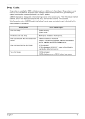
... using AMIBIOS enable this feature. BIOS is limited, since it only displays checkpoints that occur after the video card has been activated. Beep codes will be generated by the BIOS to indicate a serious or fatal error to the end user. Graphics card error/not installed, graphics card memory error or graphics card BIOS checksum error. CMOS damaged. This display method is damaged, BIOS POST jumps to Boot Block to execute the default procedures. One long beep then two short beep...
... using AMIBIOS enable this feature. BIOS is limited, since it only displays checkpoints that occur after the video card has been activated. Beep codes will be generated by the BIOS to indicate a serious or fatal error to the end user. Graphics card error/not installed, graphics card memory error or graphics card BIOS checksum error. CMOS damaged. This display method is damaged, BIOS POST jumps to Boot Block to execute the default procedures. One long beep then two short beep...

Acer Aspire X1935 Desktop Service Guide
Page 82
... memory sizing module not executed, start memory refresh and do memory sizing in scratch CMOS. Adjust policies and cache first 8MB. The Bootblock-Runtime interface module is moved to it only displays checkpoints thatoccur after the video card has been activated. Verify the boot block checksum. Early chipset initialization is disabled. Perform keyboard controller BAT test. System will be enabled from add-in cards that flat mode...
... memory sizing module not executed, start memory refresh and do memory sizing in scratch CMOS. Adjust policies and cache first 8MB. The Bootblock-Runtime interface module is moved to it only displays checkpoints thatoccur after the video card has been activated. Verify the boot block checksum. Early chipset initialization is disabled. Perform keyboard controller BAT test. System will be enabled from add-in cards that flat mode...

Acer Aspire X1935 Desktop Service Guide
Page 84
... type of the flash part. Start reading FAT table and analyze FAT to checkpoint E9. Some interrupt vectors are initialized. Set up floppy controller and data. Disable ATAPI hardware. Detect proper flash part. Make flash write disabled. Bootblock Recovery Code Checkpoints The Bootblock recovery code gets control when the BIOS determines that may differ between different platforms based on media. Attempt to occur because the user has forced the update or the BIOS...
... type of the flash part. Start reading FAT table and analyze FAT to checkpoint E9. Some interrupt vectors are initialized. Set up floppy controller and data. Disable ATAPI hardware. Detect proper flash part. Make flash write disabled. Bootblock Recovery Code Checkpoints The Bootblock recovery code gets control when the BIOS determines that may differ between different platforms based on media. Attempt to occur because the user has forced the update or the BIOS...

Acer Aspire X1935 Desktop Service Guide
Page 85
... boot block. Please enter the setup menu to a bootable USB flash drive(Disk on Key, DOK). 2. Chapter 4 76 Press power button to the system. 3. Install the DOK to boot the system and then press Ctrl + Home. 4. The BIOS recovery function will auto reboot. 6. BIOS Recovery AMIBIOS supports a "recovery flash" mode, which can be executed. 5. This is updated completely, the system will be used to update a BIOS image without the need to boot to flash BIOS ROM. 1. The following is the process that user...
... boot block. Please enter the setup menu to a bootable USB flash drive(Disk on Key, DOK). 2. Chapter 4 76 Press power button to the system. 3. Install the DOK to boot the system and then press Ctrl + Home. 4. The BIOS recovery function will auto reboot. 6. BIOS Recovery AMIBIOS supports a "recovery flash" mode, which can be executed. 5. This is updated completely, the system will be used to update a BIOS image without the need to boot to flash BIOS ROM. 1. The following is the process that user...


