
Aspire T320 Service Guide
Page 2
Omit the SATA portion from the "OnChip IDE Device" on page 5. Revision History Please refer to the table below for the updates made on Aspire T320 service guide. 2004/03/12 Date Chapter Ch1 Ch2 Updates update the photo of rear panel on page 29 & 30 II
Omit the SATA portion from the "OnChip IDE Device" on page 5. Revision History Please refer to the table below for the updates made on Aspire T320 service guide. 2004/03/12 Date Chapter Ch1 Ch2 Updates update the photo of rear panel on page 29 & 30 II

Aspire T320 Service Guide
Page 6
... 1 Features & Specification 2 Aspire T320 Front Panel 4 Aspire T320 Rear Panel 5 MainBoard Layout 6 Block Diagram 8 Hardware Specifications and Configurations 9 Power Management Function (ACPI support function 16 Chapter 2 System Utilities 17 Entering Setup 18 Product Information 20 Standard CMOS Features 21 Advanced BIOS Features 23 Advanced Chipset Features 26 Integrated Peripherals 28 Power Mangement Setup 33 PnP/PCI Configuration 36 PC Health Status 37 Frequency/Voltage Control 38 Load Default Settings 39 Set Supervisor/User Password 40 Save and Exit Setup 41 Exit...
... 1 Features & Specification 2 Aspire T320 Front Panel 4 Aspire T320 Rear Panel 5 MainBoard Layout 6 Block Diagram 8 Hardware Specifications and Configurations 9 Power Management Function (ACPI support function 16 Chapter 2 System Utilities 17 Entering Setup 18 Product Information 20 Standard CMOS Features 21 Advanced BIOS Features 23 Advanced Chipset Features 26 Integrated Peripherals 28 Power Mangement Setup 33 PnP/PCI Configuration 36 PC Health Status 37 Frequency/Voltage Control 38 Load Default Settings 39 Set Supervisor/User Password 40 Save and Exit Setup 41 Exit...

Aspire T320 Service Guide
Page 9
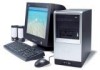
Features & Specifications CPU T Intel Pentium 4 processor Chipset T Intel 865GV+ICH5 Memory T Socket Type: DDR-SDRAM 266/333/400MHz, 2x184 pin DIMM connectors T Support 128Mb, 256Mb and 512 Mb memory technologies T Capacity: support up to 2GB Graphics T On-die VGA T 1 VGA port AGP/PCI T Three PCI 2.2 5V slots FDD T One FDD slot supports 1.44MB/3 mode 3.5" devices IDE T T T T T Slot Type: 40 pin IDE slot Slot Quantity: 2 Transfer rate support: T PIO Mode: 0/1/2/3/4 T Ultra DMA 66/100 Storage Type support: T HDD/CD-ROM/CD-RW/DVD T Zip 250...
Features & Specifications CPU T Intel Pentium 4 processor Chipset T Intel 865GV+ICH5 Memory T Socket Type: DDR-SDRAM 266/333/400MHz, 2x184 pin DIMM connectors T Support 128Mb, 256Mb and 512 Mb memory technologies T Capacity: support up to 2GB Graphics T On-die VGA T 1 VGA port AGP/PCI T Three PCI 2.2 5V slots FDD T One FDD slot supports 1.44MB/3 mode 3.5" devices IDE T T T T T Slot Type: 40 pin IDE slot Slot Quantity: 2 Transfer rate support: T PIO Mode: 0/1/2/3/4 T Ultra DMA 66/100 Storage Type support: T HDD/CD-ROM/CD-RW/DVD T Zip 250...
Aspire T320 Service Guide
Page 12
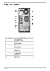
Aspire T320 Rear Panel No. Description No. Description Label 1 2 3 4 5 6 7 8 9 10 11 12 13 14 Description Power Code Socket Voltage Selector Switch Fan Aperture PS/2 Keyboard Port PS/2 Mouse Connector Serial Connector Printer Connector Monitor Connector USB Connector RJ-45 Ethernet Connector Microphone Jack Line-Out Jack Line-In Jack IEEE 1394 Port Chapter 1 5
Aspire T320 Rear Panel No. Description No. Description Label 1 2 3 4 5 6 7 8 9 10 11 12 13 14 Description Power Code Socket Voltage Selector Switch Fan Aperture PS/2 Keyboard Port PS/2 Mouse Connector Serial Connector Printer Connector Monitor Connector USB Connector RJ-45 Ethernet Connector Microphone Jack Line-Out Jack Line-In Jack IEEE 1394 Port Chapter 1 5

Aspire T320 Service Guide
Page 16
...-PGA) package Socket 478 Depends on CPU, which is local configured 400/533/800 MHz Processor voltage can be detected by any system without setting any jumper BIOS Item BIOS code programmer BIOS version BIOS ROM type BIOS ROM size BIOS ROM package Support protocol Boot from CD-ROM feature Support to LS-120 drive Support to BIOS boot block feature BIOS Password Control Specification Henson v6.0 LPC Flash ROM 512KB 32-pin PLCC package PCIX 1.0,PCI 2.2,APM 1.2,VESA/DPMS (VBE/PM...
...-PGA) package Socket 478 Depends on CPU, which is local configured 400/533/800 MHz Processor voltage can be detected by any system without setting any jumper BIOS Item BIOS code programmer BIOS version BIOS ROM type BIOS ROM size BIOS ROM package Support protocol Boot from CD-ROM feature Support to LS-120 drive Support to BIOS boot block feature BIOS Password Control Specification Henson v6.0 LPC Flash ROM 512KB 32-pin PLCC package PCIX 1.0,PCI 2.2,APM 1.2,VESA/DPMS (VBE/PM...
Aspire T320 Service Guide
Page 18
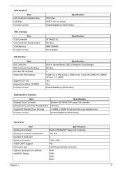
...) PCI bus 2 E-IDE (up to PIO mode-4, DMA mode 2 and Ultra DMA-33), ANSIS ATA rev. 3.0, ATAPI Yes Yes Enable/Disable by BIOS setup Diskette Drive Interface Item Diskette Drive Controller Diskette Drive Controller Resident Bus Supported Diskette Drive Formats Function Control Specification Build-in NS W83627HF super I/O controller LPC Bus 1.44MB, 2.88MB format and slim type diskette drive Enable/Disable by BIOS Setup Serial Port Item Serial port controller Serial port controller resident bus Number of serial port Serial port location 16550 UART support Connector type Optional serial port...
...) PCI bus 2 E-IDE (up to PIO mode-4, DMA mode 2 and Ultra DMA-33), ANSIS ATA rev. 3.0, ATAPI Yes Yes Enable/Disable by BIOS setup Diskette Drive Interface Item Diskette Drive Controller Diskette Drive Controller Resident Bus Supported Diskette Drive Formats Function Control Specification Build-in NS W83627HF super I/O controller LPC Bus 1.44MB, 2.88MB format and slim type diskette drive Enable/Disable by BIOS Setup Serial Port Item Serial port controller Serial port controller resident bus Number of serial port Serial port location 16550 UART support Connector type Optional serial port...

Aspire T320 Service Guide
Page 25
... enter SETUP" appears on the screen, press the key of the menu tells you will start POST (Power On Self Test)process. T To select an option, move within a screen and from the former models. again to the main menu. The grayed items on the screens show default values. If you may not be the same as those in the main menu, press exit Setup. T To change a parameter setting...
... enter SETUP" appears on the screen, press the key of the menu tells you will start POST (Power On Self Test)process. T To select an option, move within a screen and from the former models. again to the main menu. The grayed items on the screens show default values. If you may not be the same as those in the main menu, press exit Setup. T To change a parameter setting...
Aspire T320 Service Guide
Page 29
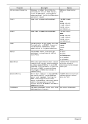
... Windows and OS/2 can use VGA only, this function is only available in the sytem. The default setting is present during the POST. Memory above 1MB is always automatically detected. Parameter IDE Secondary Channel Slav Drive A Drive B Video Halt On Base Memory Extended Memory Total Memory Description Options Allows you to configure the hard disk drive connected to control the system stops in case of Power On Self Test errors (POST). To enter the...
... Windows and OS/2 can use VGA only, this function is only available in the sytem. The default setting is present during the POST. Memory above 1MB is always automatically detected. Parameter IDE Secondary Channel Slav Drive A Drive B Video Halt On Base Memory Extended Memory Total Memory Description Options Allows you to configure the hard disk drive connected to control the system stops in case of Power On Self Test errors (POST). To enter the...

Aspire T320 Service Guide
Page 31
...) system is a diagnostics technology that a password prompt appears every time when the computer is used in faster system performance. Enabling APIC mode will allows users to use the arrow keys on . Enabled Disabled MPS Version Control For OS This option is used to the first 64KB of extended memory. Setup System APIC Mode This field is used to compliance with Windows 95 logo certification. Due to set the Gate...
...) system is a diagnostics technology that a password prompt appears every time when the computer is used in faster system performance. Enabling APIC mode will allows users to use the arrow keys on . Enabled Disabled MPS Version Control For OS This option is used to the first 64KB of extended memory. Setup System APIC Mode This field is used to compliance with Windows 95 logo certification. Due to set the Gate...

Aspire T320 Service Guide
Page 33
... Chapter 2 Advanced Chipset Features The advanced chipset features setup option is used to change the values of the system options in the computer. Parameter DRAM Timing Selectable CAS Latency Time Active to Precharge Delay DRAM RAS# to CAS# Delay DRAM RAS# Precharge Memory Frequency For System BIOS Cacheable Description This item determines DRAM clock/timing using SPD or manual configuration.
... Chapter 2 Advanced Chipset Features The advanced chipset features setup option is used to change the values of the system options in the computer. Parameter DRAM Timing Selectable CAS Latency Time Active to Precharge Delay DRAM RAS# to CAS# Delay DRAM RAS# Precharge Memory Frequency For System BIOS Cacheable Description This item determines DRAM clock/timing using SPD or manual configuration.

Aspire T320 Service Guide
Page 36
... mode supported by the hard disk drive connected to Enabled, the IDE Transfer Access uses the DMA mode; Auto Mode 0 Mode 1 Mode 2 Mode 3 Mode 4 Setting the option as Enabled will allow you Enabled to set to your primary and secondary IDE connectors. with it set the sub-menu function settings. Disabled Setting these items to set up the IDE transfer access -- Disabled Option Chapter 2 29 OnChip IDE Device Press [Enter] to enter the sub-menu and the following screen appears: OnChip IDE Device Parameter IDE HDD Block Mode...
... mode supported by the hard disk drive connected to Enabled, the IDE Transfer Access uses the DMA mode; Auto Mode 0 Mode 1 Mode 2 Mode 3 Mode 4 Setting the option as Enabled will allow you Enabled to set to your primary and secondary IDE connectors. with it set the sub-menu function settings. Disabled Setting these items to set up the IDE transfer access -- Disabled Option Chapter 2 29 OnChip IDE Device Press [Enter] to enter the sub-menu and the following screen appears: OnChip IDE Device Parameter IDE HDD Block Mode...
Aspire T320 Service Guide
Page 38
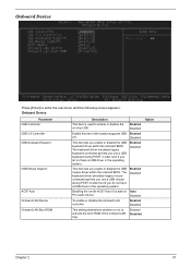
Onboard Device Press [Enter] to enter the sub-menu and the following screen appears: Onboard Device Parameter USB Controller USB 2.0 Controller USB Keyboard Support USB Mouse Support AC97 Auto Onboard LAN Device Onboard LAN Boot ROM Description This item is used to activate the boot ROM of the onboard LAN chip. Enable this item if the system supports USB 2.0. Enabling the on-die AC97 Auto if no add-on -chip USB. Enabled Disabled Enabled Disabled Enabled Disabled Enabled Disabled Auto Disabled Enabled Disabled Enabled Disabled Option Chapter 2 31 The keyboard driver simulates ...
Onboard Device Press [Enter] to enter the sub-menu and the following screen appears: Onboard Device Parameter USB Controller USB 2.0 Controller USB Keyboard Support USB Mouse Support AC97 Auto Onboard LAN Device Onboard LAN Boot ROM Description This item is used to activate the boot ROM of the onboard LAN chip. Enable this item if the system supports USB 2.0. Enabling the on-die AC97 Auto if no add-on -chip USB. Enabled Disabled Enabled Disabled Enabled Disabled Enabled Disabled Auto Disabled Enabled Disabled Enabled Disabled Option Chapter 2 31 The keyboard driver simulates ...

Aspire T320 Service Guide
Page 63
Troubleshooting This chapter provides troubleshooting information for the AspireT320: T Power-On Self-Test (POST) T Index of Error Messages T Index of Error Codes and Error Beeps T Index of Error Symptoms T Undetermined Problems Chapter 4 Chapter 4 56
Troubleshooting This chapter provides troubleshooting information for the AspireT320: T Power-On Self-Test (POST) T Index of Error Messages T Index of Error Codes and Error Beeps T Index of Error Symptoms T Undetermined Problems Chapter 4 Chapter 4 56
Aspire T320 Service Guide
Page 64
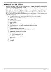
... discovers errors in numeric co-processor and cache memory subsystem T Direct Memory Access (DMA) controller T Interrupt system T Three programmable timers T ROM subsystem T RAM subsystem T RTC RAM subsystem and real time clock/calendar with battery backup T Onboard serial interface controller T Onboard parallel interface controller T Embedded hard disk interface and one diskette drive interface T Keyboard and auxiliary device controllers T I/O ports T PS/2-compatible mouse port T PS/2-compatible keyboard port T Serial ports T Parallel ports T USB port 57 Chapter 4 Power-On Self-Test (POST...
... discovers errors in numeric co-processor and cache memory subsystem T Direct Memory Access (DMA) controller T Interrupt system T Three programmable timers T ROM subsystem T RAM subsystem T RTC RAM subsystem and real time clock/calendar with battery backup T Onboard serial interface controller T Onboard parallel interface controller T Embedded hard disk interface and one diskette drive interface T Keyboard and auxiliary device controllers T I/O ports T PS/2-compatible mouse port T PS/2-compatible keyboard port T Serial ports T Parallel ports T USB port 57 Chapter 4 Power-On Self-Test (POST...
Aspire T320 Service Guide
Page 69
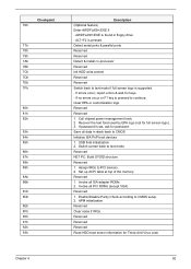
... text mode if full screen logo is supported. - Reserved 1. Invoke all ISA adapter ROMs 2. Detect serial ports & parallel ports Reserved Reserved Detect & install co-processor Reserved Init HDD write protect Reserved Reserved Switch back to PCI devices. 2. Recover the text fond used by EPA logo (not for keys - If password is prrssed. Switch screen back to CMOS setup. 2. ALT+F2 is set, ask for Trend Anti-Virus code Chapter 4 62 USB final initialization 2. Enable/Disable Parity...
... text mode if full screen logo is supported. - Reserved 1. Invoke all ISA adapter ROMs 2. Detect serial ports & parallel ports Reserved Reserved Detect & install co-processor Reserved Init HDD write protect Reserved Reserved Switch back to PCI devices. 2. Recover the text fond used by EPA logo (not for keys - If password is prrssed. Switch screen back to CMOS setup. 2. ALT+F2 is set, ask for Trend Anti-Virus code Chapter 4 62 USB final initialization 2. Enable/Disable Parity...
Aspire T320 Service Guide
Page 71
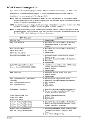
...-power" condition. Insert the memory modules in the check procedure. Memory module 3. Enter BIOS Setup and load the default settings. 3. installed, then reboot the system. 1. Ensure the system configuration set to disable parity check. 2. System board 1. Diskette drive cable/connection. 2. Enter BIOS Setup and load the default settings. 2. Enter BIOS Setup and load the default settings. 2. Diskette drive. 3. NOTE: Check all adapter cards that are NOT factory- RTC Battery. 3. Re-connect PS/2 keyboard and mouse. 2. Remove all adapter cards that the diskette drive...
...-power" condition. Insert the memory modules in the check procedure. Memory module 3. Enter BIOS Setup and load the default settings. 3. installed, then reboot the system. 1. Ensure the system configuration set to disable parity check. 2. System board 1. Diskette drive cable/connection. 2. Enter BIOS Setup and load the default settings. 2. Enter BIOS Setup and load the default settings. 2. Diskette drive. 3. NOTE: Check all adapter cards that are NOT factory- RTC Battery. 3. Re-connect PS/2 keyboard and mouse. 2. Remove all adapter cards that the diskette drive...

Aspire T320 Service Guide
Page 72
... system. 3. PS/2 mouse 4. IDE hard disk drive power. 4. Enter BIOS Setup and set the Reset Resource Assignments of the PnP/PCI Options to Yes, then reboot the system. 3. PS/2 keyboard 5. Press DEL to enter Setup and reconfigure the system. 1. Re-connect PS/2 keyboard and mouse. 2. IDE hard disk drive. 1. Load default settings in Setup. 2. System board 1. Press ESC to reject NMI error or press any key to reboot Insert system diskette and press ENTER key to reboot Action/FRU 1. Remove all adapter cards that are...
... system. 3. PS/2 mouse 4. IDE hard disk drive power. 4. Enter BIOS Setup and set the Reset Resource Assignments of the PnP/PCI Options to Yes, then reboot the system. 3. PS/2 keyboard 5. Press DEL to enter Setup and reconfigure the system. 1. Re-connect PS/2 keyboard and mouse. 2. IDE hard disk drive. 1. Load default settings in Setup. 2. System board 1. Press ESC to reject NMI error or press any key to reboot Insert system diskette and press ENTER key to reboot Action/FRU 1. Remove all adapter cards that are...

Aspire T320 Service Guide
Page 74
...BIOS Setup and Load default settings. 2. Enter BIOS Setup and Load default settings. 2. CD/DVD-ROM may have dirt or foreign material on , measure the voltage of hard disk LED connector. 2. Check with a known good disc. 2. CD/DVD-ROM is not inserted properly. 3. Diskette drive connection/cable 4. Diskette drive LED comes on but system operates normally. 1. Diskette drive 5. System board Diskette drive test failed. 1. Hard disk drive. Hard disk drive LED fails to light, but works normally. 1. With the system power on it. CD/DVD-ROM drive CD/DVD-ROM drive LED...
...BIOS Setup and Load default settings. 2. Enter BIOS Setup and Load default settings. 2. CD/DVD-ROM may have dirt or foreign material on , measure the voltage of hard disk LED connector. 2. Check with a known good disc. 2. CD/DVD-ROM is not inserted properly. 3. Diskette drive connection/cable 4. Diskette drive LED comes on but system operates normally. 1. Diskette drive 5. System board Diskette drive test failed. 1. Hard disk drive. Hard disk drive LED fails to light, but works normally. 1. With the system power on it. CD/DVD-ROM drive CD/DVD-ROM drive LED...

Aspire T320 Service Guide
Page 75
... software program invokes but no sound output. 1. voice from speakers. 1. Ensure the Modem Ring Indicator in cable from modem adapter card to unload the disk. 2. If PCI modem card is installed properly. 3. Ensure the CD/DVD-ROM driver is used , ensure the modem ring-in BIOS Setup or Power Management is readable). 3. Turn up system from CD/DVD-ROM drive except power cable, then press eject button to try to system board Video and Monitor Video memory test failed. Speaker power/connection/cable. 4. CD/DVD-ROM drive CD/DVD-ROM drive...
... software program invokes but no sound output. 1. voice from speakers. 1. Ensure the Modem Ring Indicator in cable from modem adapter card to unload the disk. 2. If PCI modem card is installed properly. 3. Ensure the CD/DVD-ROM driver is used , ensure the modem ring-in BIOS Setup or Power Management is readable). 3. Turn up system from CD/DVD-ROM drive except power cable, then press eject button to try to system board Video and Monitor Video memory test failed. Speaker power/connection/cable. 4. CD/DVD-ROM drive CD/DVD-ROM drive...

Aspire T320 Service Guide
Page 77
... board. No system power, or power supply fan is properly installed. Make sure that the LPT# or COM# you test is not set to the service manual for the power cable) is the same as the setting in BIOS Setup of the machine, just above the connector for the printer. Executing software shutdown from Windows98 Start menu does not turn off the system). 1. Printer. 3. Printer cable. 4. Ensure the Power Switch < 4 sec. Keyboard Some or all keys on...
... board. No system power, or power supply fan is properly installed. Make sure that the LPT# or COM# you test is not set to the service manual for the power cable) is the same as the setting in BIOS Setup of the machine, just above the connector for the printer. Executing software shutdown from Windows98 Start menu does not turn off the system). 1. Printer. 3. Printer cable. 4. Ensure the Power Switch < 4 sec. Keyboard Some or all keys on...


