Service Guide
Page 7
... 39 System Check Procedures 40 Power System Check 40 System External Inspection 40 System Internal Inspection 40 Beep Codes 41 Checkpoints 42 BIOS Recovery 44 Jumper and Connector Information 45 M/B Placement 45 Jumper Setting 46 Setting Jumper 46 FRU (Field Replaceable Unit) List 53 Aspire R3700 Exploded Diagram 54 Aspire R3700 FRU List 55 vii
... 39 System Check Procedures 40 Power System Check 40 System External Inspection 40 System Internal Inspection 40 Beep Codes 41 Checkpoints 42 BIOS Recovery 44 Jumper and Connector Information 45 M/B Placement 45 Jumper Setting 46 Setting Jumper 46 FRU (Field Replaceable Unit) List 53 Aspire R3700 Exploded Diagram 54 Aspire R3700 FRU List 55 vii
Service Guide
Page 17
...8226; Resume method: Resume to original state by pushing external switch button,modem ring inand USB keyboard for Windows. • Resume recovery time 3-5sec. On board device power management support. Power Management Function(ACPI support function) Device Standby Mode • Independent power ... method: Resume to original state by pushing external switch Button,modem ring in ,keyboard an mouse for APM mode. • Resume recovery time :7-10sec Suspend Mode • Independent power management timer(2-120minutes,time step=10minute)or pushing extern switch button. • CPU goes...
...8226; Resume method: Resume to original state by pushing external switch button,modem ring inand USB keyboard for Windows. • Resume recovery time 3-5sec. On board device power management support. Power Management Function(ACPI support function) Device Standby Mode • Independent power ... method: Resume to original state by pushing external switch Button,modem ring in ,keyboard an mouse for APM mode. • Resume recovery time :7-10sec Suspend Mode • Independent power management timer(2-120minutes,time step=10minute)or pushing extern switch button. • CPU goes...
Service Guide
Page 48
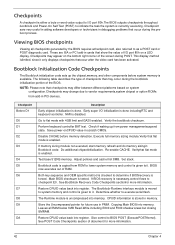
.... Do additional chipsetinitialization. Both key sequence and OEM specific method is checked to determine if BIOSrecovery is disabled. See Bootblock Recovery Code Checkpoints sectionfor more information. 42 Chapter 4 See POST Code Checkpoints section of document for future use in cards that may...If memory sizing module not executed, start memory refresh and do memory sizingin Bootblock code. Test base 512KB memory. If BIOS recovery is enabled. Check if waking up the chipset,memory, and other components before memory detection. Verifythat flat mode is necessary,...
.... Do additional chipsetinitialization. Both key sequence and OEM specific method is checked to determine if BIOSrecovery is disabled. See Bootblock Recovery Code Checkpoints sectionfor more information. 42 Chapter 4 See POST Code Checkpoints section of document for future use in cards that may...If memory sizing module not executed, start memory refresh and do memory sizingin Bootblock code. Test base 512KB memory. If BIOS recovery is enabled. Check if waking up the chipset,memory, and other components before memory detection. Verifythat flat mode is necessary,...
Service Guide
Page 49
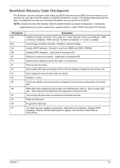
...Set up floppy controller and data. Check the validity of checkpoints that the found flash part size equals the recovery file size. NOTE: Checkpoints may occur during the Bootblock recovery portion of the flash part. Checkpoints maychange due to the current configuration of the BIOS. Search for pre-... E0 E9 EA EB EF F0 F1 F2 F3 F5 FA FB F4 FC FD FF Description Initialize the floppy controller in root directory. Recovery file not found flash part size. Chapter 4 43 Verify that may differ between different platforms based on media. Give control to read from...
...Set up floppy controller and data. Check the validity of checkpoints that the found flash part size equals the recovery file size. NOTE: Checkpoints may occur during the Bootblock recovery portion of the flash part. Checkpoints maychange due to the current configuration of the BIOS. Search for pre-... E0 E9 EA EB EF F0 F1 F2 F3 F5 FA FB F4 FC FD FF Description Initialize the floppy controller in root directory. Recovery file not found flash part size. Chapter 4 43 Verify that may differ between different platforms based on media. Give control to read from...
Service Guide
Page 50
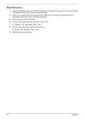
... done. Rename the target BIOS to "amiboot.rom".Plug the USB disk to computer that you want to enter BIOS Setup. 4. AMIBIOS Recovery is finished. 44 Chapter 4 Choose "Save & Exit Setup " and press "Enter" key. 5-1.Choose " OK " and press "Enter " key. 6.... Press "Del" Key to recovery the system BIOS. 2. BIOS Recovery 1. Power on the system, BIOS recovery will reboot automatically after flash update completed successfully. 3. Copy the target BIOS rom file to a USB disk. Choose " Load Default Settings...
... done. Rename the target BIOS to "amiboot.rom".Plug the USB disk to computer that you want to enter BIOS Setup. 4. AMIBIOS Recovery is finished. 44 Chapter 4 Choose "Save & Exit Setup " and press "Enter" key. 5-1.Choose " OK " and press "Enter " key. 6.... Press "Del" Key to recovery the system BIOS. 2. BIOS Recovery 1. Power on the system, BIOS recovery will reboot automatically after flash update completed successfully. 3. Copy the target BIOS rom file to a USB disk. Choose " Load Default Settings...

