Service Guide
Page 36
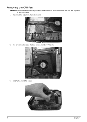
Use screwdriver to loosen the three screws from the motherboard. 2. Removing the CPU Fan WARNING:The heat sink becomes very hot when the system is on. Disconnect fan cable from the CPU cooler. 3. Lift CPU fan from CPU cooler. 30 Chapter 3 NEVER touch the heat sink with any metal or with your hands. 1.
Use screwdriver to loosen the three screws from the motherboard. 2. Removing the CPU Fan WARNING:The heat sink becomes very hot when the system is on. Disconnect fan cable from the CPU cooler. 3. Lift CPU fan from CPU cooler. 30 Chapter 3 NEVER touch the heat sink with any metal or with your hands. 1.
Service Guide
Page 37
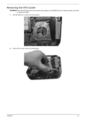
Use screwdriver to loosen the four screws. 2. Removing the CPU Cooler WARNING:The heat sink becomes very hot when the system is on. NEVER touch the heat sink with any metal or with your hands. 1. Chapter 3 31 Lift the CPU cooler from the motherboard.
Use screwdriver to loosen the four screws. 2. Removing the CPU Cooler WARNING:The heat sink becomes very hot when the system is on. NEVER touch the heat sink with any metal or with your hands. 1. Chapter 3 31 Lift the CPU cooler from the motherboard.
Service Guide
Page 41
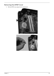
Pull the S/PDIF cover away from the motherboard. Chapter 3 35 Removing the S/PDIF Cover 1.
Pull the S/PDIF cover away from the motherboard. Chapter 3 35 Removing the S/PDIF Cover 1.
Service Guide
Page 42
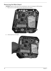
Remove the four screws that secure the main board to damage the EMI shielding. 1. Removing the Main Board WARNING:Please be careful when lift the motherboard,in order not to the chassis. 2. Lift the board from the chassis. 36 Chapter 3
Remove the four screws that secure the main board to damage the EMI shielding. 1. Removing the Main Board WARNING:Please be careful when lift the motherboard,in order not to the chassis. 2. Lift the board from the chassis. 36 Chapter 3
Service Guide
Page 44
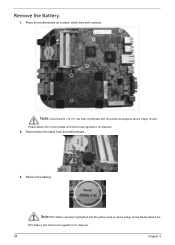
Note:Circuit boards >10 cm² has been highlighted with the yellow circle as above image shows.Please detach the RTC battery and follow local regulations for disposal. 38 Chapter 3 Please detach the Circuit boards and follow local regulations for disposal. 2. Note:RTC battery has been highlighted with the yellow rectangle as above image shows. Disconnector the cable from the motherboard. 3. Remove the battery. Place the motherboard on a clean, static-free work surface. Remove the Battery. 1.
Note:Circuit boards >10 cm² has been highlighted with the yellow circle as above image shows.Please detach the RTC battery and follow local regulations for disposal. 38 Chapter 3 Please detach the Circuit boards and follow local regulations for disposal. 2. Note:RTC battery has been highlighted with the yellow rectangle as above image shows. Disconnector the cable from the motherboard. 3. Remove the battery. Place the motherboard on a clean, static-free work surface. Remove the Battery. 1.
Service Guide
Page 52
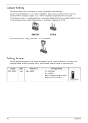
Use the motherboard jumpers to set jumper for correct configuration of the mainboard. Jumper Setting The section explains how to set system configuration options. The illustrations show a 2-pin ... a 3-pin jumper.Pins 1 and 2 are placed on the correct pins. Jumpers with more Than one pin are numbered. CLR_CMOS1 46 Chapter 5 Setting Jumper Use the motherboard jumpers to set system configuration options. Jumper CLR_CMOS1 Type Description 3-pin Clear CMOS Setting (default) 1-2: NORMAL 2-3: CLEAR Before clearing theCMOS, make sure toturn off the...
Use the motherboard jumpers to set jumper for correct configuration of the mainboard. Jumper Setting The section explains how to set system configuration options. The illustrations show a 2-pin ... a 3-pin jumper.Pins 1 and 2 are placed on the correct pins. Jumpers with more Than one pin are numbered. CLR_CMOS1 46 Chapter 5 Setting Jumper Use the motherboard jumpers to set system configuration options. Jumper CLR_CMOS1 Type Description 3-pin Clear CMOS Setting (default) 1-2: NORMAL 2-3: CLEAR Before clearing theCMOS, make sure toturn off the...

