Service Guide
Page 7
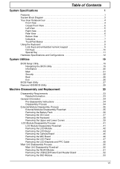
Table of Contents System Specifications 1 Features 1 System Block Diagram 3 Your Acer Notebook tour 4 Front View 4 Closed Front View 5 Left View 5 Right View 6 Rear View 6 Bottom View 7 Indicators 7 TouchPad Basics 8 Using the Keyboard 9 Lock Keys...BIOS Setup Utility 19 Navigating the BIOS Utility 19 Information 20 Main 21 Security 22 Boot 25 Exit 26 BIOS Flash Utility 27 Remove HDD/BIOS Utility 29 Machine Disassembly and Replacement 33 Disassembly Requirements 33 Related Information 33 General Information 34 Pre-disassembly Instructions 34 Disassembly Process 34...
Table of Contents System Specifications 1 Features 1 System Block Diagram 3 Your Acer Notebook tour 4 Front View 4 Closed Front View 5 Left View 5 Right View 6 Rear View 6 Bottom View 7 Indicators 7 TouchPad Basics 8 Using the Keyboard 9 Lock Keys...BIOS Setup Utility 19 Navigating the BIOS Utility 19 Information 20 Main 21 Security 22 Boot 25 Exit 26 BIOS Flash Utility 27 Remove HDD/BIOS Utility 29 Machine Disassembly and Replacement 33 Disassembly Requirements 33 Related Information 33 General Information 34 Pre-disassembly Instructions 34 Disassembly Process 34...
Service Guide
Page 8
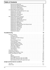
... Random Loss of BIOS Settings 83 LCD Failure 84 Built-In Keyboard Failure 84 TouchPad Failure 85 Internal Speaker Failure 85 Internal Microphone Failure 87 HDD Not Operating Correctly 88 USB Failure (Rightside 89 Power Button Failure 89 External Mouse Failure 90 Other Failures 90 Intermittent Problems 91 Undetermined Problems 91...
... Random Loss of BIOS Settings 83 LCD Failure 84 Built-In Keyboard Failure 84 TouchPad Failure 85 Internal Speaker Failure 85 Internal Microphone Failure 87 HDD Not Operating Correctly 88 USB Failure (Rightside 89 Power Button Failure 89 External Mouse Failure 90 Other Failures 90 Intermittent Problems 91 Undetermined Problems 91...
Service Guide
Page 11
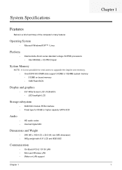
... 533FSB processors • Intel 945GSE + ICH7M Chipset System Memory NOTE: It is not possible for end users to upgrade the Aspire one memory. • One DDRII SO-DIMM slots support 512MB to 1024MB system memory • 512MB on board memory • 1MB Flash BIOS Display and... graphics • 8.9" Wide Screen LCD (1024x600) • LED backlight LCD Storage subsystem • 8GB SSD module PATA interface • Fixed type for 80GB or higher capacity SATA HDD...
... 533FSB processors • Intel 945GSE + ICH7M Chipset System Memory NOTE: It is not possible for end users to upgrade the Aspire one memory. • One DDRII SO-DIMM slots support 512MB to 1024MB system memory • 512MB on board memory • 1MB Flash BIOS Display and... graphics • 8.9" Wide Screen LCD (1024x600) • LED backlight LCD Storage subsystem • 8GB SSD module PATA interface • Fixed type for 80GB or higher capacity SATA HDD...

Service Guide
Page 17
... the battery is closed. Indicators The computer has several easy-to pass through the casing unhindered. Icon Function Battery Description Indicates the computer's battery status. HDD Indicates when the hard disk drive is active. NOTE: 1. Battery release latch Releases the battery for removal. 3 Ventilation slots • Vents enable the computer to...
... the battery is closed. Indicators The computer has several easy-to pass through the casing unhindered. Icon Function Battery Description Indicates the computer's battery status. HDD Indicates when the hard disk drive is active. NOTE: 1. Battery release latch Releases the battery for removal. 3 Ventilation slots • Vents enable the computer to...

Service Guide
Page 23
... controller Memory size DIMM socket number Supports memory size per socket Supports maximum memory size Supports DIMM type Supports DIMM Speed System Storage SSD Item HDD Specification • FCBGA • Ball Count: 998 balls • Package Size: 27 mm x 27 mm • Ball pitch: 0.8-mm uniform ...USB or ZIF connector (PATA compatible) Interface • 2GB, 4GB or 8GB • USB connector BTO (not user selectable) • 9.5mm height, 2.5" HDD • Easily removable no more than two screws • SATA bus • 80GB/100GB/120GB/160GB and above • 5400 and 7200 rpm (follow...
... controller Memory size DIMM socket number Supports memory size per socket Supports maximum memory size Supports DIMM type Supports DIMM Speed System Storage SSD Item HDD Specification • FCBGA • Ball Count: 998 balls • Package Size: 27 mm x 27 mm • Ball pitch: 0.8-mm uniform ...USB or ZIF connector (PATA compatible) Interface • 2GB, 4GB or 8GB • USB connector BTO (not user selectable) • 9.5mm height, 2.5" HDD • Easily removable no more than two screws • SATA bus • 80GB/100GB/120GB/160GB and above • 5400 and 7200 rpm (follow...

Service Guide
Page 30
... Name: HDD Serial Number: INTEL Castle Point 00008030320000000000 System BIOS Version: VGA BIOS Version: v0.2103 Intel V1585 Serial Number: Asset Tag Number: Product Name: Manufacturer Name: UUID: ZG008160067 Acer 405FE2E9A4E1D4118251001E684CE894 Rev. 3.5 F1 Help ESC Exit &#...8593;↓ Select Item ←→ Select Menu F5/F6 Change Values Enter SelectXSubMenu NOTE: The system information is an identifier standard used in software construction, standardized by the Open Software Foundation (OSF) as part of HDD...
... Name: HDD Serial Number: INTEL Castle Point 00008030320000000000 System BIOS Version: VGA BIOS Version: v0.2103 Intel V1585 Serial Number: Asset Tag Number: Product Name: Manufacturer Name: UUID: ZG008160067 Acer 405FE2E9A4E1D4118251001E684CE894 Rev. 3.5 F1 Help ESC Exit &#...8593;↓ Select Item ←→ Select Menu F5/F6 Change Values Enter SelectXSubMenu NOTE: The system information is an identifier standard used in software construction, standardized by the Open Software Foundation (OSF) as part of HDD...
Service Guide
Page 35
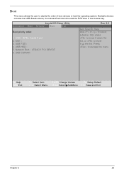
... to move it down the list, or to move it up the list. InsydeH20 Setup Utility Information Main Security Boot Exit Boot priority order: 1. USB HDD : 5. IDE1 : 3.
... to move it down the list, or to move it up the list. InsydeH20 Setup Utility Information Main Security Boot Exit Boot priority order: 1. USB HDD : 5. IDE1 : 3.
Service Guide
Page 37
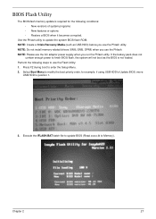
... utility. Select Boot Menu to modify the boot priority order, for the following steps to finish BIOS flash, the system will not boot as USB HDD) before you use the Flash Utility: 1. Use the Phlash utility to position 1. 3. Perform the following conditions: • New versions of system programs • New features... Utility The BIOS flash memory update is not loaded. NOTE: Create a Crisis Recovery Media (such as the BIOS is required for example, if using USB HDD to Update BIOS, move USB HDD to update the system BIOS flash ROM.
... utility. Select Boot Menu to modify the boot priority order, for the following steps to finish BIOS flash, the system will not boot as USB HDD) before you use the Flash Utility: 1. Use the Phlash utility to position 1. 3. Perform the following conditions: • New versions of system programs • New features... Utility The BIOS flash memory update is not loaded. NOTE: Create a Crisis Recovery Media (such as the BIOS is required for example, if using USB HDD to Update BIOS, move USB HDD to update the system BIOS flash ROM.

Service Guide
Page 39
See the image below. Press 2. 3. Remove HDD/BIOS Utility This section provide you with removing HDD/BIOS method: Remove HDD Password: • If you key in hdd_pw 15494 0 2. Chapter 2 29 Key in wrong HDD password three times, Hdd password error code displays. Select one upper-case string from the list. 4. To reset the HDD password, run HDD_PW.EXE as follows: 1. Reboot system and key in the selected string (0KJFN42 or UVEIQ96) on the HDD User Password screen.
See the image below. Press 2. 3. Remove HDD/BIOS Utility This section provide you with removing HDD/BIOS method: Remove HDD Password: • If you key in hdd_pw 15494 0 2. Chapter 2 29 Key in wrong HDD password three times, Hdd password error code displays. Select one upper-case string from the list. 4. To reset the HDD password, run HDD_PW.EXE as follows: 1. Reboot system and key in the selected string (0KJFN42 or UVEIQ96) on the HDD User Password screen.
Service Guide
Page 43
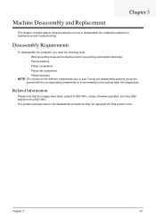
... may differ slightly from a SSD SKU. The product previews seen in size. Chapter 3 33 Related Information Please note that the images were taken using the HDD SKU, unless otherwise specified, and may not represent the final product color. Machine Disassembly and Replacement Chapter 3 This chapter contains step-by-step procedures on...
... may differ slightly from a SSD SKU. The product previews seen in size. Chapter 3 33 Related Information Please note that the images were taken using the HDD SKU, unless otherwise specified, and may not represent the final product color. Machine Disassembly and Replacement Chapter 3 This chapter contains step-by-step procedures on...
Service Guide
Page 60
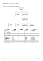
Main Unit Disassembly Process Main Unit Disassembly Flowchart Screw List Step WLAN USB/LED/Power Board (HDD SKU) USB/LED/Power Board (SSD SKU) SSD Module Mainboard Speaker Module HDD Module HDD Carrier Thermal Module Screw M2*3 (NL) M2*3 (NL) M2*3 (NL) M2*3 M2*3 M2*3 M2.5*4 M3*3.5 M2*3 Quantity 1 3 4 2 1 4 2 4 3 Color Black Black Black Black Black Black Black Black Black Part No. 86.S0207.001 86.S0207.001 86.S0207.001 86.S0207.001 86.S0207.001 86.S0207.001 86.D01V7.001 86.TDY07.003 86.S0207.001 50 Chapter 3
Main Unit Disassembly Process Main Unit Disassembly Flowchart Screw List Step WLAN USB/LED/Power Board (HDD SKU) USB/LED/Power Board (SSD SKU) SSD Module Mainboard Speaker Module HDD Module HDD Carrier Thermal Module Screw M2*3 (NL) M2*3 (NL) M2*3 (NL) M2*3 M2*3 M2*3 M2.5*4 M3*3.5 M2*3 Quantity 1 3 4 2 1 4 2 4 3 Color Black Black Black Black Black Black Black Black Black Part No. 86.S0207.001 86.S0207.001 86.S0207.001 86.S0207.001 86.S0207.001 86.S0207.001 86.D01V7.001 86.TDY07.003 86.S0207.001 50 Chapter 3
Service Guide
Page 62
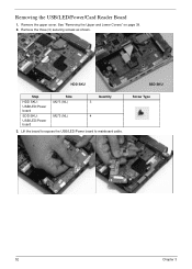
Removing the USB/LED/Power/Card Reader Board 1. Screw Type 52 Chapter 3 Remove the upper cover. HDD SKU SSD SKU Step HDD SKU: USB/LED/Power board SDD SKU: USB/LED/Power board Size M2*3 (NL) M2*3 (NL) Quantity 3 4 3. See "Removing the Upper and Lower Covers" on page 39. 2. Remove the three (3) securing screws as shown. Lift the board to expose the USB/LED/Power board to mainboard cable.
Removing the USB/LED/Power/Card Reader Board 1. Screw Type 52 Chapter 3 Remove the upper cover. HDD SKU SSD SKU Step HDD SKU: USB/LED/Power board SDD SKU: USB/LED/Power board Size M2*3 (NL) M2*3 (NL) Quantity 3 4 3. See "Removing the Upper and Lower Covers" on page 39. 2. Remove the three (3) securing screws as shown. Lift the board to expose the USB/LED/Power board to mainboard cable.

Service Guide
Page 68
Removing the Hard Disk Drive Module IMPORTANT:The HDD is only available on page 55. 2. Remove the mainboard. See "Removing the Mainboard" on the Aspire one HDD SKU. 1. Step HDD Module Size M2.5*4 (NL) Quantity 2 3. Remove the two securing screws to device, avoid pressing down on it or placing heavy objects on top of it. 58 Chapter 3 Screw Type NOTE: To prevent damage to release the carrier. Hold the carrier and slide the HDD away from the mainboard.
Removing the Hard Disk Drive Module IMPORTANT:The HDD is only available on page 55. 2. Remove the mainboard. See "Removing the Mainboard" on the Aspire one HDD SKU. 1. Step HDD Module Size M2.5*4 (NL) Quantity 2 3. Remove the two securing screws to device, avoid pressing down on it or placing heavy objects on top of it. 58 Chapter 3 Screw Type NOTE: To prevent damage to release the carrier. Hold the carrier and slide the HDD away from the mainboard.
Service Guide
Page 69
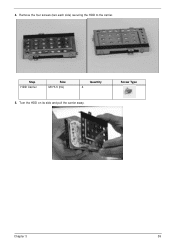
Turn the HDD on its side and pull the carrier away. 4. Step HDD Carrier Size M3*3.5 (NL) Quantity 4 5. Screw Type Chapter 3 59 Remove the four screws (two each side) securing the HDD to the carrier.
Turn the HDD on its side and pull the carrier away. 4. Step HDD Carrier Size M3*3.5 (NL) Quantity 4 5. Screw Type Chapter 3 59 Remove the four screws (two each side) securing the HDD to the carrier.

Service Guide
Page 78
Replacing the Hard Disk Drive Module IMPORTANT:The HDD is only available on the Aspire one HDD computer SKU. 1. Replace the four screws (two each side) to secure the carrier. 3. Hold the carrier and slide the HDD toward the mainboard until the interface connects. 4. Replacing the Speaker Module 1. Replace the two securing screws. Replace the four securing screws. 68 Chapter 3 Replace the Speaker Module in the HDD carrier. 2. Place the HDD in the lower cover. 2.
Replacing the Hard Disk Drive Module IMPORTANT:The HDD is only available on the Aspire one HDD computer SKU. 1. Replace the four screws (two each side) to secure the carrier. 3. Hold the carrier and slide the HDD toward the mainboard until the interface connects. 4. Replacing the Speaker Module 1. Replace the two securing screws. Replace the four securing screws. 68 Chapter 3 Replace the Speaker Module in the HDD carrier. 2. Place the HDD in the lower cover. 2.
Service Guide
Page 82
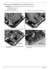
Replace the three or four screws (depending on SKU) to the module and close the cable latch. the cable latch. 72 Chapter 3 Connect the FFC cable to secure the module. Connect the FFC cable to the board. 2. Connect the cable to the mainboard and close 5. HDD SKU SSD SKU 4. Replacing the USB/LED/Power/Card Reader Board IMPORTANT:Before installing the USB board, take care of the following items: • Check that LED isn`t broken • SLIDER work smoothly 1. Turn the board over and place it in the lower case. 3.
Replace the three or four screws (depending on SKU) to the module and close the cable latch. the cable latch. 72 Chapter 3 Connect the FFC cable to secure the module. Connect the FFC cable to the board. 2. Connect the cable to the mainboard and close 5. HDD SKU SSD SKU 4. Replacing the USB/LED/Power/Card Reader Board IMPORTANT:Before installing the USB board, take care of the following items: • Check that LED isn`t broken • SLIDER work smoothly 1. Turn the board over and place it in the lower case. 3.
Service Guide
Page 93
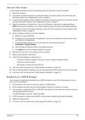
.... 4. Adjust the brightness to the desired resolution. If the display is too dim at a time to correct the problem. 1. If HDD information is missing from the operating system DVD and follow the onscreen prompts. 11. Replace the Motherboard. 6. b. c. Remove and reinstall the...not resolved, see "Online Support Information" on adjusting settings. Abnormal Video Display If video displays abnormally, perform the following actions one at the highest brightness setting, the LCD is faulty and should be replaced. Reboot the computer. 2. Click Apply and check...
.... 4. Adjust the brightness to the desired resolution. If the display is too dim at a time to correct the problem. 1. If HDD information is missing from the operating system DVD and follow the onscreen prompts. 11. Replace the Motherboard. 6. b. c. Remove and reinstall the...not resolved, see "Online Support Information" on adjusting settings. Abnormal Video Display If video displays abnormally, perform the following actions one at the highest brightness setting, the LCD is faulty and should be replaced. Reboot the computer. 2. Click Apply and check...
Service Guide
Page 98
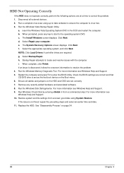
...f. Run Windows Check Disk by entering chkdsk /r from a known good date using up-to-date software to the operating system DVD. Replace the HDD. When prompted, press any recently added hardware and associated software. 8. d. Select Repair your computer. Select the appropriate operating system, and click Next... the problem. 1. Run the Windows Disk Defragmenter. NOTE: Click Load Drivers if controller drives are required. Click Next. HDD Not Operating Correctly If the HDD does not operate correctly, perform the following actions one at a time to resolve the problem. 4. b.
...f. Run Windows Check Disk by entering chkdsk /r from a known good date using up-to-date software to the operating system DVD. Replace the HDD. When prompted, press any recently added hardware and associated software. 8. d. Select Repair your computer. Select the appropriate operating system, and click Next... the problem. 1. Run the Windows Disk Defragmenter. NOTE: Click Load Drivers if controller drives are required. Click Next. HDD Not Operating Correctly If the HDD does not operate correctly, perform the following actions one at a time to resolve the problem. 4. b.
Service Guide
Page 123
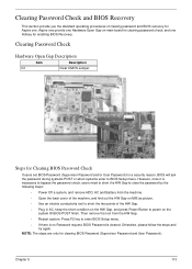
... bypass the password check, users need to short the HW Gap to clear the password by the following steps: • Power Off a system, and remove HDD, AC and Battery from the HW Gap. • Restart system. Aspire one provide one Hardware Open Gap on main board for clearing password check, and...
... bypass the password check, users need to short the HW Gap to clear the password by the following steps: • Power Off a system, and remove HDD, AC and Battery from the HW Gap. • Restart system. Aspire one provide one Hardware Open Gap on main board for clearing password check, and...
Service Guide
Page 126
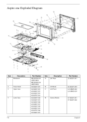
Aspire one Exploded Diagram Item 1 Description Mainboard 2 Power Board 3 Upper Case 4 Lower Case 116 Part Number MB.S0306.001 (SDD SKU) MB.S0506.001 (HDD SKU) 55.S0207.001 60.S0207.001 60.S0607.001 60.S0307.001 60.S0707.001 60.S0207.002 60.S0407.001 60.S0607.002 60.S0807.001 60.S0307.002 60.S0507.001 60.S0707.002 60.S0907.001 Item 15 Description Left Hinge 16 LCD Bezel 17 LCD Panel 18 Camera Module Part Number 33.S0207.001 60.S0207.004 LK.08905.002 LK.0890D.001 57.S0207.001 57.S0207.002 Chapter 6
Aspire one Exploded Diagram Item 1 Description Mainboard 2 Power Board 3 Upper Case 4 Lower Case 116 Part Number MB.S0306.001 (SDD SKU) MB.S0506.001 (HDD SKU) 55.S0207.001 60.S0207.001 60.S0607.001 60.S0307.001 60.S0707.001 60.S0207.002 60.S0407.001 60.S0607.002 60.S0807.001 60.S0307.002 60.S0507.001 60.S0707.002 60.S0907.001 Item 15 Description Left Hinge 16 LCD Bezel 17 LCD Panel 18 Camera Module Part Number 33.S0207.001 60.S0207.004 LK.08905.002 LK.0890D.001 57.S0207.001 57.S0207.002 Chapter 6


