Service Guide
Page 7
... 51 System Check Procedures 52 Power System Check 52 System External Inspection 52 System Internal Inspection 52 Beep Codes 53 Checkpoints 54 Viewing BIOS checkpoints 54 Bootblock Initialization Code Checkpoints 54 Bootblock Recovery Code Checkpoints 56 BIOS Recovery 57 System Architecture 59 Block Diagram 59 Mainboard Layout 60 Jumper Setting 61 vii
... 51 System Check Procedures 52 Power System Check 52 System External Inspection 52 System Internal Inspection 52 Beep Codes 53 Checkpoints 54 Viewing BIOS checkpoints 54 Bootblock Initialization Code Checkpoints 54 Bootblock Recovery Code Checkpoints 56 BIOS Recovery 57 System Architecture 59 Block Diagram 59 Mainboard Layout 60 Jumper Setting 61 vii
Service Guide
Page 10
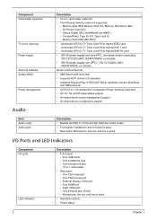
... (xD) - External display (VGA) port - One HDMI port - Component Card reader (optional) TV tuner (optional) Power supply Antivirus software System BIOS Power management Audio Item Audio codec Audio jacks Description • 16-in jacks I/O Ports and LED Indicators Component I and II) - Memory Stick PRO...co-module • 300 W power supply unit (PFC), 100-127v/220v-240V (4SATA1PATA) co-module Norton Internet Security • AMI Kernel with Acer skin • Supports ACPI revision 2.0 standard • Supports Plug and Play, STR(S3)/STD(S4), hardware monitor, Multi Boot, and DMI ...
... (xD) - External display (VGA) port - One HDMI port - Component Card reader (optional) TV tuner (optional) Power supply Antivirus software System BIOS Power management Audio Item Audio codec Audio jacks Description • 16-in jacks I/O Ports and LED Indicators Component I and II) - Memory Stick PRO...co-module • 300 W power supply unit (PFC), 100-127v/220v-240V (4SATA1PATA) co-module Norton Internet Security • AMI Kernel with Acer skin • Supports ACPI revision 2.0 standard • Supports Plug and Play, STR(S3)/STD(S4), hardware monitor, Multi Boot, and DMI ...
Service Guide
Page 15
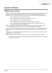
This memory area is no need to as "BIOS", "Setup", or "Setup utility" in this case, the system cannot retain configuration values in a battery-backed nonvolatile memory called the complementary metaloxide semiconductor (CMOS) Setup ...
This memory area is no need to as "BIOS", "Setup", or "Setup utility" in this case, the system cannot retain configuration values in a battery-backed nonvolatile memory called the complementary metaloxide semiconductor (CMOS) Setup ...

Service Guide
Page 18
... the hour-minute-second format. 10 Chapter 2 Core speed of the CPU installed on the system. Physical CPU count Total size of the BIOS setup utility. Serial number of CPU installed on the system. Type of the system. Asset tag number of the system. Product name of ...this system. Main The Main menu displays basic information about the system. Parameter System BIOS Version Build Date Processor Core Frequency Count Memory Size Product Name System Serial Number Asset Tag Number System Date System Time (hh:mm:ss)...
... the hour-minute-second format. 10 Chapter 2 Core speed of the CPU installed on the system. Physical CPU count Total size of the BIOS setup utility. Serial number of CPU installed on the system. Type of the system. Asset tag number of the system. Product name of ...this system. Main The Main menu displays basic information about the system. Parameter System BIOS Version Build Date Processor Core Frequency Count Memory Size Product Name System Serial Number Asset Tag Number System Date System Time (hh:mm:ss)...
Service Guide
Page 20
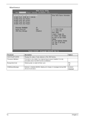
Selects power on state for Num Lock. Enables or disables BIOS to display error beeps or messages during USB device enumeration. Miscellaneous Parameter AHCI Port0/1/2/3/4/5 Processor Multiplier Bootup Num-lock USB Beep Message Description Displays the status of auto detection of the AHCI device. This field is disabled. Option On Off Enabled Disabled 12 Chapter 2 It is only accessible when the EIST function is only visible if an engineering processor installed.
Selects power on state for Num Lock. Enables or disables BIOS to display error beeps or messages during USB device enumeration. Miscellaneous Parameter AHCI Port0/1/2/3/4/5 Processor Multiplier Bootup Num-lock USB Beep Message Description Displays the status of auto detection of the AHCI device. This field is disabled. Option On Off Enabled Disabled 12 Chapter 2 It is only accessible when the EIST function is only visible if an engineering processor installed.

Service Guide
Page 25
... and close the Setup Utility. Type the original password then press Enter. 3. Setting a system password 1. Type a password then press Enter. Retype the password to the BIOS Setup Utility. Select Yes to select password parameter (Change Supervisor Password or Change User Password) menu then press Enter. 2. Changing the system password 1. Security Parameter...
... and close the Setup Utility. Type the original password then press Enter. 3. Setting a system password 1. Type a password then press Enter. Retype the password to the BIOS Setup Utility. Select Yes to select password parameter (Change Supervisor Password or Change User Password) menu then press Enter. 2. Changing the system password 1. Security Parameter...
Service Guide
Page 26
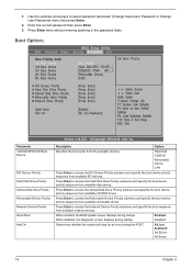
... then press Enter. 3. Press Enter to access the Network Device Priority submenu and specify the boot sequence from available CD/DVD drives. When enabled, the BIOS splash screen displays during the POST. Press Enter to access the Optical Disk Drive Priority submenu and specify the boot device priority sequence from available...
... then press Enter. 3. Press Enter to access the Network Device Priority submenu and specify the boot sequence from available CD/DVD drives. When enabled, the BIOS splash screen displays during the POST. Press Enter to access the Optical Disk Drive Priority submenu and specify the boot device priority sequence from available...

Service Guide
Page 27
...computer. The Optimal settings are designed for maximum system performance, but may not work best for all the changes and return to leave the BIOS Setup Utility and reboot the computer, so the new system configuration parameters can take effect. Select this feature, select Load Default Settings from... Setup from the Exit menu and press Enter. Chapter 2 19 Select this option to the BIOS Setup Utility. Then, select OK to allow the BIOS to automatically load optimal defaults to the BIOS Setup Utility. Select this option and press Enter to save changes that you have made as ...
...computer. The Optimal settings are designed for maximum system performance, but may not work best for all the changes and return to leave the BIOS Setup Utility and reboot the computer, so the new system configuration parameters can take effect. Select this feature, select Load Default Settings from... Setup from the Exit menu and press Enter. Chapter 2 19 Select this option to the BIOS Setup Utility. Then, select OK to allow the BIOS to automatically load optimal defaults to the BIOS Setup Utility. Select this option and press Enter to save changes that you have made as ...
Service Guide
Page 60
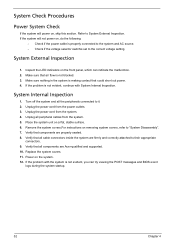
... panel, which can try viewing the POST messages and BIOS event logs during the system startup. 52 Chapter 4 Make sure nothing in the system is making contact that all peripheral cables from the power outlets. 3. Turn off the system and all components are Acer-qualified and supported. 10. Verify that could short...
... panel, which can try viewing the POST messages and BIOS event logs during the system startup. 52 Chapter 4 Make sure nothing in the system is making contact that all peripheral cables from the power outlets. 3. Turn off the system and all components are Acer-qualified and supported. 10. Verify that could short...
Service Guide
Page 61
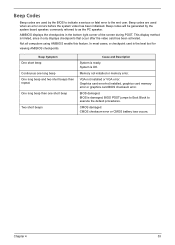
... limited, since it only displays checkpoints that occur after the video card has been activated. Beep codes will be generated by the BIOS to indicate a serious or fatal error to the end user. Chapter 4 53 Beep Symptom One short beep Continuous one short beep Two short beeps...the bottom right corner of the screen during POST. Graphics card error/not installed, graphics card memory error or graphics card BIOS checksum error. This display method is damaged, BIOS POST jumps to Boot Block to execute the default procedures. One long beep then one long beep One long beep and ...
... limited, since it only displays checkpoints that occur after the video card has been activated. Beep codes will be generated by the BIOS to indicate a serious or fatal error to the end user. Chapter 4 53 Beep Symptom One short beep Continuous one short beep Two short beeps...the bottom right corner of the screen during POST. Graphics card error/not installed, graphics card memory error or graphics card BIOS checksum error. This display method is damaged, BIOS POST jumps to Boot Block to execute the default procedures. One long beep then one long beep One long beep and ...

Service Guide
Page 62
... specific method is checked to determine if BIOSrecovery is available. Store the Uncompressed pointer for future use in scratch CMOS. Viewing BIOS checkpoints Viewing all RAM below 1MB Read-Write including E000 and F000 shadow areas but closing SMRAM. 54 Chapter 4 Bootblock Initialization... 8MB. Bootblock code is copied from ROM to RAM for debugging. See Bootblock Recovery Code Checkpoints sectionfor more information. Copying Main BIOS into register. NMI is enabled. Stack will hang here if checksum is done including RTC and keyboard controller. Checkpoints may occur ...
... specific method is checked to determine if BIOSrecovery is available. Store the Uncompressed pointer for future use in scratch CMOS. Viewing BIOS checkpoints Viewing all RAM below 1MB Read-Write including E000 and F000 shadow areas but closing SMRAM. 54 Chapter 4 Bootblock Initialization... 8MB. Bootblock code is copied from ROM to RAM for debugging. See Bootblock Recovery Code Checkpoints sectionfor more information. Copying Main BIOS into register. NMI is enabled. Stack will hang here if checksum is done including RTC and keyboard controller. Checkpoints may occur ...

Service Guide
Page 63
System is reserved for more information. This range is waking from one platform to BIOS POST (ExecutePOSTKernel). Chapter 4 55 Give control to the next. OEM memory detection/configuration error. Checkpoint DA DC E1-E8 ECEE Description Restore CPUID value back into register. See POST Code Checkpoints section of document for chipset vendors & system manufacturers. The error associated with this value may be different from ACPI S3 state.
System is reserved for more information. This range is waking from one platform to BIOS POST (ExecutePOSTKernel). Chapter 4 55 Give control to the next. OEM memory detection/configuration error. Checkpoint DA DC E1-E8 ECEE Description Restore CPUID value back into register. See POST Code Checkpoints section of document for chipset vendors & system manufacturers. The error associated with this value may be different from ACPI S3 state.
Service Guide
Page 64
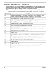
... F000:FFF0h. 56 Chapter 4 Jump back to occur because the user has forced the update or the BIOS checksum is corrupt. Start reading FAT table and analyze FAT to the current configuration of the BIOS. Disable L1 cache. Read error occurred on system configuration. Recovery file not found. Check the validity of...cluster by the recovery file. Erase the flash part Program the flash part. Bootblock Recovery Code Checkpoints The Bootblock recovery code gets control when the BIOS determines that a BIOS recovery needs to checkpoint EB. The flash has been updated successfully.
... F000:FFF0h. 56 Chapter 4 Jump back to occur because the user has forced the update or the BIOS checksum is corrupt. Start reading FAT table and analyze FAT to the current configuration of the BIOS. Disable L1 cache. Read error occurred on system configuration. Recovery file not found. Check the validity of...cluster by the recovery file. Erase the flash part Program the flash part. Bootblock Recovery Code Checkpoints The Bootblock recovery code gets control when the BIOS determines that a BIOS recovery needs to checkpoint EB. The flash has been updated successfully.
Service Guide
Page 65
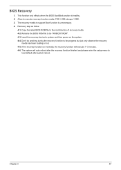
Insert the recovery device to execute recovery function media: FDD / USB storage / ODD. 3. The system will execute 1~3 minutes. 4-6. Rename the BIOS ROM file to be progress but just only observe the recovery media has been loading or not. 4-5. If the recovery function run normally, the recovery ... the system. 4-4. Recovery step as follow: 4-1. Don't do anything during the recovery function to the root directory of recovery media. 4-2. Chapter 4 57 Copy the latest BIOS ROM file to be "AMIBOOT.ROM". 4-3. This function only effects when the...
Insert the recovery device to execute recovery function media: FDD / USB storage / ODD. 3. The system will execute 1~3 minutes. 4-6. Rename the BIOS ROM file to be progress but just only observe the recovery media has been loading or not. 4-5. If the recovery function run normally, the recovery ... the system. 4-4. Recovery step as follow: 4-1. Don't do anything during the recovery function to the root directory of recovery media. 4-2. Chapter 4 57 Copy the latest BIOS ROM file to be "AMIBOOT.ROM". 4-3. This function only effects when the...


