Acer Desktop User's Guide
Page 3
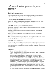
... table. iii Information for accessibility Be sure that could be seriously damaged. • Slots and openings are provided for plug as disconnecting device Observe the following guidelines when connecting and disconnecting power to the power supply unit: Install the power supply unit before connecting the power cord to protect it could result in installation unless proper ventilation is easily accessible and located as close to prevent battery leakage,
... table. iii Information for accessibility Be sure that could be seriously damaged. • Slots and openings are provided for plug as disconnecting device Observe the following guidelines when connecting and disconnecting power to the power supply unit: Install the power supply unit before connecting the power cord to protect it could result in installation unless proper ventilation is easily accessible and located as close to prevent battery leakage,
Acer Desktop User's Guide
Page 5
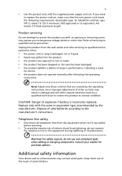
... the supplied power supply cord set , make sure that are covered by the operating instructions, since improper adjustment of other risks. Dispose of used batteries according to service this product from lightning, do not use non-compliant parts when adding or changing components. For safety reasons, do not connect the telephone line to replace the power cord set . Unplug this product yourself, as opening or removing covers may expose you need for purchase options...
... the supplied power supply cord set , make sure that are covered by the operating instructions, since improper adjustment of other risks. Dispose of used batteries according to service this product from lightning, do not use non-compliant parts when adding or changing components. For safety reasons, do not connect the telephone line to replace the power cord set . Unplug this product yourself, as opening or removing covers may expose you need for purchase options...
Acer Desktop User's Guide
Page 11
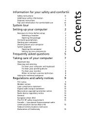
...-power license-exempt radio communication devices (RSS-210) 15 Federal Communications Comission Declaration of your computer 7 Important tips 7 Cleaning and servicing 7 To clean your computer and keyboard 7 To clean your pointing device 7 To clean your monitor 8 When to know before setup 2 Selecting a location 2 Opening the package 2 Connecting peripherals 3 Starting your computer 3 Shutting down your computer 2 Necessary to contact a service technician 8 Asking for technical...
...-power license-exempt radio communication devices (RSS-210) 15 Federal Communications Comission Declaration of your computer 7 Important tips 7 Cleaning and servicing 7 To clean your computer and keyboard 7 To clean your pointing device 7 To clean your monitor 8 When to know before setup 2 Selecting a location 2 Opening the package 2 Connecting peripherals 3 Starting your computer 3 Shutting down your computer 2 Necessary to contact a service technician 8 Asking for technical...
Acer Desktop User's Guide
Page 13
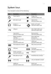
... Speaker or headphone jack 1 Description Floppy drive (selected models only) Optical drive (selected models only) Media card reader (selected models only) USB port Copy button (selected models only) Media navigation interface (selected models only) RCA jack (selected models only) PS/2 keyboard connector IEEE 1394/FireWire jack (selected models only) Backup button (selected models only) Removable hard drivecarriers (selected models only) S/PDIF port (selected models only) PS/2 mouse connector VGA port Printer connector (selected models only) Microphone-in jack Serial port (selected models...
... Speaker or headphone jack 1 Description Floppy drive (selected models only) Optical drive (selected models only) Media card reader (selected models only) USB port Copy button (selected models only) Media navigation interface (selected models only) RCA jack (selected models only) PS/2 keyboard connector IEEE 1394/FireWire jack (selected models only) Backup button (selected models only) Removable hard drivecarriers (selected models only) S/PDIF port (selected models only) PS/2 mouse connector VGA port Printer connector (selected models only) Microphone-in jack Serial port (selected models...
Acer Desktop User's Guide
Page 14
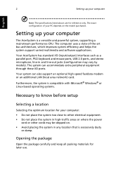
... port, PS/2 keyboard and mouse ports, USB 2.0 ports, and stereo microphone, line-in and line-out jacks (configuration may be stepped on the model purchased. Opening the package Open the...models). The exact configuration of -the-art bus architecture, which improves system efficiency and helps the system support varied multimedia and software applications. Setting up your computer English Note: The specifications listed above are for reference only. The system can also support an optional high-speed fax/data modem or an additional LAN (local area network) card. The computer uses...
... port, PS/2 keyboard and mouse ports, USB 2.0 ports, and stereo microphone, line-in and line-out jacks (configuration may be stepped on the model purchased. Opening the package Open the...models). The exact configuration of -the-art bus architecture, which improves system efficiency and helps the system support varied multimedia and software applications. Setting up your computer English Note: The specifications listed above are for reference only. The system can also support an optional high-speed fax/data modem or an additional LAN (local area network) card. The computer uses...
Acer Desktop User's Guide
Page 15
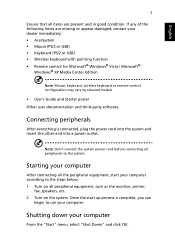
... dealer immediately: • AcerSystem • Mouse (PS/2 or USB) • Keyboard (PS/2 or USB) • Wireless keyboard with pointing function • Remote control for Microsoft® Windows® Vista / Microsoft® Windows® XP Media Center Edition Note: Mouse, keyboard, wireless keyboard or remote control configuration may vary by selected models • User's Guide and Starter poster Other user documentation and third-party software. Once the start your computer From the "Start" menu, select "Shut Down" and click...
... dealer immediately: • AcerSystem • Mouse (PS/2 or USB) • Keyboard (PS/2 or USB) • Wireless keyboard with pointing function • Remote control for Microsoft® Windows® Vista / Microsoft® Windows® XP Media Center Edition Note: Mouse, keyboard, wireless keyboard or remote control configuration may vary by selected models • User's Guide and Starter poster Other user documentation and third-party software. Once the start your computer From the "Start" menu, select "Shut Down" and click...
Acer Desktop User's Guide
Page 16
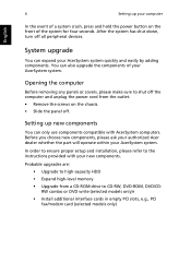
... your new components. Opening the computer Before removing any panels or covers, please make sure to shut off the computer and unplug the power cord from a CD-ROM drive to the instructions provided with AcerSystem computers. Setting up your computer English In the event of a system crash, press and hold the power button on the chassis. • Slide the panel off all peripheral devices. Probable upgrades...
... your new components. Opening the computer Before removing any panels or covers, please make sure to shut off the computer and unplug the power cord from a CD-ROM drive to the instructions provided with AcerSystem computers. Setting up your computer English In the event of a system crash, press and hold the power button on the chassis. • Slide the panel off all peripheral devices. Probable upgrades...
Acer Desktop User's Guide
Page 17
... rear panel of your system and make sure that it with a system diskette and press Ctrl + Alt + Del to the system. Do any key to turn the display back on the screen. If restarting your computer does not work, contact your computer. A: Check the LED located above the power switch. If the LED is set to the correct voltage. • Check if you plugged the power cable...
... rear panel of your system and make sure that it with a system diskette and press Ctrl + Alt + Del to the system. Do any key to turn the display back on the screen. If restarting your computer does not work, contact your computer. A: Check the LED located above the power switch. If the LED is set to the correct voltage. • Check if you plugged the power cable...
Acer Desktop User's Guide
Page 18
... type of your drive cannot read diskette, hard disk, CD or DVD information. EEnngglilisshh English 6 A: Do the following: • Make sure that the printer is connected to a power outlet and that it is crossed-out, click on the icon and deselect the Mute option. Q: No sound comes out from mute to sound on. • If headphones, earphones, or external speakers are using a good (i.e., undamaged) disk...
... type of your drive cannot read diskette, hard disk, CD or DVD information. EEnngglilisshh English 6 A: Do the following: • Make sure that the printer is connected to a power outlet and that it is crossed-out, click on the icon and deselect the Mute option. Q: No sound comes out from mute to sound on. • If headphones, earphones, or external speakers are using a good (i.e., undamaged) disk...
Acer Desktop User's Guide
Page 20
.... For cleaning instructions, refer to contact the service centers available in your mouse for maintenance instructions. To clean an optical mouse For users of your computer's internal components Asking for information on page 5 • If you keep your local dealer or distributor. You may also access the Web site (http://global.acer.com/support/index.htm) for technical assistance For technical assistance, contact your screen clean.
.... For cleaning instructions, refer to contact the service centers available in your mouse for maintenance instructions. To clean an optical mouse For users of your computer's internal components Asking for information on page 5 • If you keep your local dealer or distributor. You may also access the Web site (http://global.acer.com/support/index.htm) for technical assistance For technical assistance, contact your screen clean.
Acer Desktop User's Guide
Page 24
... device connected to operate within any 30 minute period for any single manual call initiation, and b The equipment shall go on local power, is connected to the same line as other equipment, may give rise to the same number within the following limits for compliance with Telecom's Specifications: a There shall be set to the same line. 9 Under power failure conditions this device...
... device connected to operate within any 30 minute period for any single manual call initiation, and b The equipment shall go on local power, is connected to the same line as other equipment, may give rise to the same number within the following limits for compliance with Telecom's Specifications: a There shall be set to the same line. 9 Under power failure conditions this device...
Service Guide
Page 7
... Fan Assembly 23 Removing the Processor 24 Removing the VGA Card 26 Removing the Mode Card 27 Removing the TV Card 28 Removing the Memory Modules 28 Removing the Hard Disk Drive 29 Removing the USB Board 32 Removing the Front Bezel 35 Removing the Optical Drive 37 Removing the Removable HDD 39 Removing the Card Reader 43 Removing the Power Supply 46 Removing the Mainboard 48 System Troubleshooting 51 Hardware Diagnostic Procedure 51 System Check Procedures 52 Power System Check 52 System External Inspection 52 System Internal Inspection 52 Beep Codes...
... Fan Assembly 23 Removing the Processor 24 Removing the VGA Card 26 Removing the Mode Card 27 Removing the TV Card 28 Removing the Memory Modules 28 Removing the Hard Disk Drive 29 Removing the USB Board 32 Removing the Front Bezel 35 Removing the Optical Drive 37 Removing the Removable HDD 39 Removing the Card Reader 43 Removing the Power Supply 46 Removing the Mainboard 48 System Troubleshooting 51 Hardware Diagnostic Procedure 51 System Check Procedures 52 Power System Check 52 System External Inspection 52 System Internal Inspection 52 Beep Codes...
Service Guide
Page 9
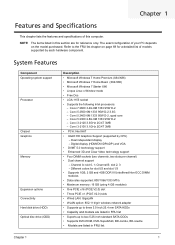
... V2.0) slots • Wired LAN: GigaLAN • WLAN option: 802.11 b/g/n wireless network adapter • Supports up to three 3.5-inch 25.4 mm SATA HDDs • Capacity and models are listed in this computer. System Features Component Operating system support Processor Chipset Graphics Memory Expansion options Connectivity Hard disk drive (HDD) Optical disc drive (ODD) Description • Microsoft Windows 7 Home Premium (X64/X86) • Microsoft Windows 7 Home Basic (X64/X86) • Microsoft Windows 7 Starter X86 • Linpus Linux x-Window mode • Free Dos...
... V2.0) slots • Wired LAN: GigaLAN • WLAN option: 802.11 b/g/n wireless network adapter • Supports up to three 3.5-inch 25.4 mm SATA HDDs • Capacity and models are listed in this computer. System Features Component Operating system support Processor Chipset Graphics Memory Expansion options Connectivity Hard disk drive (HDD) Optical disc drive (ODD) Description • Microsoft Windows 7 Home Premium (X64/X86) • Microsoft Windows 7 Home Basic (X64/X86) • Microsoft Windows 7 Starter X86 • Linpus Linux x-Window mode • Free Dos...
Service Guide
Page 10
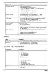
... - Four USB ports - One PS/2 mouse port - One Ethernet jack (RJ45) - Microphone, line-out, and line-in -1 card reader • Rear panel - xD-Picture Card (xD) - CompactFlash, Type I/II (CF, Type I /O ports LED indicators Description • Front panel - One HDMI port - One microphone jack - 16-in jacks • Hard drive activity • Power status 2 Chapter 1 External display (VGA) port - One PS/2 keyboard - Memory Stick PRO (MS PRO) • Avermedia H753-A TV Tuner Card PCIe Hybrid ATSC card •...
... - Four USB ports - One PS/2 mouse port - One Ethernet jack (RJ45) - Microphone, line-out, and line-in -1 card reader • Rear panel - xD-Picture Card (xD) - CompactFlash, Type I/II (CF, Type I /O ports LED indicators Description • Front panel - One HDMI port - One microphone jack - 16-in jacks • Hard drive activity • Power status 2 Chapter 1 External display (VGA) port - One PS/2 keyboard - Memory Stick PRO (MS PRO) • Avermedia H753-A TV Tuner Card PCIe Hybrid ATSC card •...
Service Guide
Page 15
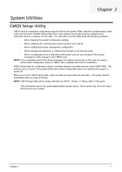
... changing the system configuration settings • When redefining the communication ports to prevent any conflicts • When modifying the power management configuration • When changing the password or making other changes to the security setup • When a configuration error is detected by the system and you are prompted ("Run Setup" message) to make changes to run the CMOS Setup Utility, make sure that you close the Setup. Before you run this guide. NOTE: CMOS Setup Utility will need to the CMOS setup...
... changing the system configuration settings • When redefining the communication ports to prevent any conflicts • When modifying the power management configuration • When changing the password or making other changes to the security setup • When a configuration error is detected by the system and you are prompted ("Run Setup" message) to make changes to run the CMOS Setup Utility, make sure that you close the Setup. Before you run this guide. NOTE: CMOS Setup Utility will need to the CMOS setup...

Service Guide
Page 18
.... Type of CPU installed on the system. Product name of the system. Serial number of the system. Core speed of this system. Set the date following the hour-minute-second format. 10 Chapter 2 Date when the BIOS setup utility was built. Physical CPU count Total size of the BIOS setup utility. Main The Main menu displays basic information about the system. Parameter System BIOS Version Build Date Processor...
.... Type of CPU installed on the system. Product name of the system. Serial number of the system. Core speed of this system. Set the date following the hour-minute-second format. 10 Chapter 2 Date when the BIOS setup utility was built. Physical CPU count Total size of the BIOS setup utility. Main The Main menu displays basic information about the system. Parameter System BIOS Version Build Date Processor...
Service Guide
Page 26
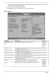
... removable drives. Press Enter to access the Removable Device Priority submenu and specify the boot device priority sequence from available network devices. When disabled, the diagnostic screen displays during startup. Boot Options Parameter 1st/2nd/3rd/4th/5th Boot Device EFI Device Priority Hard Disk Drive Priority Optical Disk Drive Priority Removable Device Priority Network Device Priority Quiet Boot Halt On Description Option Specifies the boot order from available CD/DVD drives. When enabled, the BIOS splash screen displays during startup. Press Enter twice without entering...
... removable drives. Press Enter to access the Removable Device Priority submenu and specify the boot device priority sequence from available network devices. When disabled, the diagnostic screen displays during startup. Boot Options Parameter 1st/2nd/3rd/4th/5th Boot Device EFI Device Priority Hard Disk Drive Priority Optical Disk Drive Priority Removable Device Priority Network Device Priority Quiet Boot Halt On Description Option Specifies the boot order from available CD/DVD drives. When enabled, the BIOS splash screen displays during startup. Press Enter twice without entering...

Service Guide
Page 62
... memory. Early chipset initialization is disabled. Disable CACHE before system memory is enabled at this point if needed for debugging. Verify that checkpoints may differ between different platforms based on system configuration.Checkpoints may change due to vendor requirements,system chipset or option ROMs from ROM to lower system memory and control is given to memory in scratch CMOS. Performs main BIOS checksum and updates recovery status accordingly. Restore...
... memory. Early chipset initialization is disabled. Disable CACHE before system memory is enabled at this point if needed for debugging. Verify that checkpoints may differ between different platforms based on system configuration.Checkpoints may change due to vendor requirements,system chipset or option ROMs from ROM to lower system memory and control is given to memory in scratch CMOS. Performs main BIOS checksum and updates recovery status accordingly. Restore...
Service Guide
Page 64
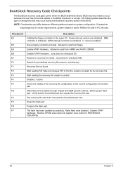
... ROM at F000:FFF0h. 56 Chapter 4 Recovery file not found. Make flash write enabled through chipset and OEM specific method. NOTE: Checkpoints may occur during the Bootblock recovery portion of the flash part. Disable ATAPI hardware. The following table describes the type of checkpoints that the found flash part size. Erase the flash part Program the flash part. Start reading FAT table and analyze FAT to read from add-in PCI devices...
... ROM at F000:FFF0h. 56 Chapter 4 Recovery file not found. Make flash write enabled through chipset and OEM specific method. NOTE: Checkpoints may occur during the Bootblock recovery portion of the flash part. Disable ATAPI hardware. The following table describes the type of checkpoints that the found flash part size. Erase the flash part Program the flash part. Start reading FAT table and analyze FAT to read from add-in PCI devices...
Service Guide
Page 68
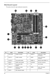
No Label 1 PCIE116X1 2 PCIE1~3 3 AUDIO_F 4 SPDIF1 5~8 USBF1~4 9 SATA2~5 10 LEDH1 60 Description PCIEx 16 socket PCIEx1 sockets Front audio header SPDIF audio header Front panel USB headers SATA2 to 5 cable connectors LED indicator header No Label 11 SATA0~1 12 PWR1 13 DIMM1~4 14 CPUFAN1 15 U2 16 PWR2 Description SATA0 and 1 cable connectors 24-pin ATX power connector Memory slots DIMM1 to 4 CPU fan connector CPU Socket 4-pin +12V power connector Chapter 5 Mainboard Layout This section shows the major mainboard components.
No Label 1 PCIE116X1 2 PCIE1~3 3 AUDIO_F 4 SPDIF1 5~8 USBF1~4 9 SATA2~5 10 LEDH1 60 Description PCIEx 16 socket PCIEx1 sockets Front audio header SPDIF audio header Front panel USB headers SATA2 to 5 cable connectors LED indicator header No Label 11 SATA0~1 12 PWR1 13 DIMM1~4 14 CPUFAN1 15 U2 16 PWR2 Description SATA0 and 1 cable connectors 24-pin ATX power connector Memory slots DIMM1 to 4 CPU fan connector CPU Socket 4-pin +12V power connector Chapter 5 Mainboard Layout This section shows the major mainboard components.


