Acer Aspire M3410 Desktop Service Guide
Page 7
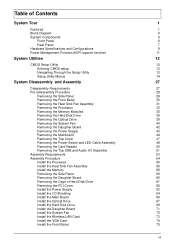
... Removing the Power Switch and LED Cable Assembly 49 Removing the Card Reader 50 Removing the Top USB and Audio I/O Assembly 51 Assembly Requirements 53 Assembly Procedure 54 Install the Processor 55 Install the Heat Sink Fan Assembly 56 Install the Memory 58 Romoving the Side Panel 59 Removing the Daughter Board 60 Removing the Cage of Hard Disk Drive 61 Removing the PCI Cover 62 Install the Power Supply 63 Install the I/O Shielding 64 Install the Main Board 65 Install the Optical Drive 67 Install the Hard Disk Drive...
... Removing the Power Switch and LED Cable Assembly 49 Removing the Card Reader 50 Removing the Top USB and Audio I/O Assembly 51 Assembly Requirements 53 Assembly Procedure 54 Install the Processor 55 Install the Heat Sink Fan Assembly 56 Install the Memory 58 Romoving the Side Panel 59 Removing the Daughter Board 60 Removing the Cage of Hard Disk Drive 61 Removing the PCI Cover 62 Install the Power Supply 63 Install the I/O Shielding 64 Install the Main Board 65 Install the Optical Drive 67 Install the Hard Disk Drive...
Acer Aspire M3410 Desktop Service Guide
Page 8
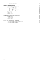
Install the Side Panel 76 System Troubleshooting 77 Hardware Diagnostic Procedure 77 System Check Procedures 78 Power System Check 78 System External Inspection 78 System Internal Inspection 78 Beep Codes 79 Checkpoints 80 BIOS Recovery 83 Jumper and Connector Information 84 M/B Placement 84 Jumper Setting 86 Setting Jumper 86 FRU (Field Replaceable Unit) List 97 Aspire M3410/M3410G Exploded Diagram 98 Aspire M3410/M3410G FRU List 100 viii
Install the Side Panel 76 System Troubleshooting 77 Hardware Diagnostic Procedure 77 System Check Procedures 78 Power System Check 78 System External Inspection 78 System Internal Inspection 78 Beep Codes 79 Checkpoints 80 BIOS Recovery 83 Jumper and Connector Information 84 M/B Placement 84 Jumper Setting 86 Setting Jumper 86 FRU (Field Replaceable Unit) List 97 Aspire M3410/M3410G Exploded Diagram 98 Aspire M3410/M3410G FRU List 100 viii
Acer Aspire M3410 Desktop Service Guide
Page 10
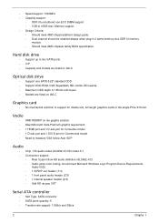
... AVLC Graphics card • No mechanical retriction to support for double slot, full length graphics cards in 2 same memory size DDR III memory module. • Should meet Microsoft Windows Logo Program Device Requirements: Audio-0002 • 1 S/PDIF-out header (1*4) • 1 front panel audio header (2*5) • 1 internal speaker header (2*4) • Add HD de-pop CKT Serial ATA controller • Slot Type: SATA connector • SATA ports quantity: 6 • Transfer rate support: 1.5Gb/s and 3Gb/s 2 Chapter 1 Memory support. •...
... AVLC Graphics card • No mechanical retriction to support for double slot, full length graphics cards in 2 same memory size DDR III memory module. • Should meet Microsoft Windows Logo Program Device Requirements: Audio-0002 • 1 S/PDIF-out header (1*4) • 1 front panel audio header (2*5) • 1 internal speaker header (2*4) • Add HD de-pop CKT Serial ATA controller • Slot Type: SATA connector • SATA ports quantity: 6 • Transfer rate support: 1.5Gb/s and 3Gb/s 2 Chapter 1 Memory support. •...
Acer Aspire M3410 Desktop Service Guide
Page 11
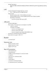
... Type support: • HDD/CD-ROME/CD-RW/DVD-ROM/DVD-RW/DVD+RW/DVD Dual/DVD SuperMultiPlus/ Blu-Ray ODD LAN • • Controller: Realtek 8111E Gigabit Ethernet controller • Port: 1 x RJ45 rear port from Gigabit Ethernet Design Criteria: • Should be worked under 10/100/1000Mbs environment • Reserved disable function on board buzzer Extension slot • Support one PCIe x 16 slot • Support two PCIe x 1 slots • Support one PCI slot Rear I/O connectors • 1 PS/2 Keyboard port • 1 PS/2 Mouse port • 1 HDMI port (need...
... Type support: • HDD/CD-ROME/CD-RW/DVD-ROM/DVD-RW/DVD+RW/DVD Dual/DVD SuperMultiPlus/ Blu-Ray ODD LAN • • Controller: Realtek 8111E Gigabit Ethernet controller • Port: 1 x RJ45 rear port from Gigabit Ethernet Design Criteria: • Should be worked under 10/100/1000Mbs environment • Reserved disable function on board buzzer Extension slot • Support one PCIe x 16 slot • Support two PCIe x 1 slots • Support one PCI slot Rear I/O connectors • 1 PS/2 Keyboard port • 1 PS/2 Mouse port • 1 HDMI port (need...
Acer Aspire M3410 Desktop Service Guide
Page 12
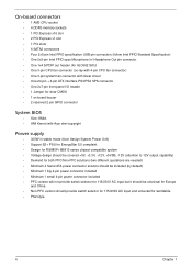
...; One 3-pin CPU fan connector (co-lay with 4-pin CPU fan connector) • One 3-pin system fan connector with linear circuit • One 24-pin + 4-pin ATX interface PS3/PS2 SPS connector • One 2x7-pin front panel I/O header • 1 Jumper for clear CMOS • 1 on board buzzer • 2 reserved 2-pin GPIO connector System BIOS • Size: 8Mbit • AMI Kernel with Acer skin/copyright Power supply • 300W in stable mode (Acer Assign System Power Unit) • Support 82...
...; One 3-pin CPU fan connector (co-lay with 4-pin CPU fan connector) • One 3-pin system fan connector with linear circuit • One 24-pin + 4-pin ATX interface PS3/PS2 SPS connector • One 2x7-pin front panel I/O header • 1 Jumper for clear CMOS • 1 on board buzzer • 2 reserved 2-pin GPIO connector System BIOS • Size: 8Mbit • AMI Kernel with Acer skin/copyright Power supply • 300W in stable mode (Acer Assign System Power Unit) • Support 82...
Acer Aspire M3410 Desktop Service Guide
Page 16
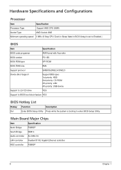
... Minimum operating speed 0 MHz (If Stop CPU Clock in Sleep State in BIOS Setup is set to Enabled.) BIOS Item Specification BIOS code programer AMI Kernel with Acer skin BIOS version P01-B3 BIOS ROM type SPI ROM BIOS ROM size 8Mb Support protocol SMBIOS(DMI)2.4/DMI2.0 Device Boot Support Support BBS spec 1st priority: HDD 2nd priority: CD-ROM 3th priority: LAN 4th priority: USB device Support to LS-120 drive YES Support to BIOS boot block feature YES BIOS Hotkey List Hotkey Function Description Del Enter BIOS Setup Utility Press...
... Minimum operating speed 0 MHz (If Stop CPU Clock in Sleep State in BIOS Setup is set to Enabled.) BIOS Item Specification BIOS code programer AMI Kernel with Acer skin BIOS version P01-B3 BIOS ROM type SPI ROM BIOS ROM size 8Mb Support protocol SMBIOS(DMI)2.4/DMI2.0 Device Boot Support Support BBS spec 1st priority: HDD 2nd priority: CD-ROM 3th priority: LAN 4th priority: USB device Support to LS-120 drive YES Support to BIOS boot block feature YES BIOS Hotkey List Hotkey Function Description Del Enter BIOS Setup Utility Press...
Acer Aspire M3410 Desktop Service Guide
Page 17
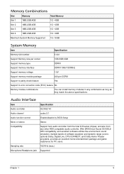
... Memory Supported 1G~16GB System Memory Item Specification Memory slot number 4 slot Support Memory size per socket 1GB/2GB/4GB Support memory type DDRIII Support memory interface DDRIII 1066/1333MHz Support memory voltage 1.5V Support memory module package 240-pin DDRIII Support to parity check feature Yes Support to error correction code (ECC) feature No Memory module combinations You can install memory modules in any other HDA compatible audio controller. With EAX/Direct Sound 3D/I3DL2/ A3D compatibility, and excellent software utilities...
... Memory Supported 1G~16GB System Memory Item Specification Memory slot number 4 slot Support Memory size per socket 1GB/2GB/4GB Support memory type DDRIII Support memory interface DDRIII 1066/1333MHz Support memory voltage 1.5V Support memory module package 240-pin DDRIII Support to parity check feature Yes Support to error correction code (ECC) feature No Memory module combinations You can install memory modules in any other HDA compatible audio controller. With EAX/Direct Sound 3D/I3DL2/ A3D compatibility, and excellent software utilities...
Acer Aspire M3410 Desktop Service Guide
Page 18
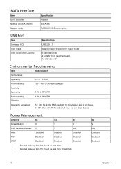
SATA Interface Item SATA controller Number of SATA channel Support mode Specification RS880P SATA X 6 RAID/AHCI/IDE mode option USB Port Item Universal HCI USB Class USB Connectors Quantity Specification USB 2.0/1.1 Support legacy keyboard for legacy mode 6 back real ports 4 ports for front daughter board 4 ports reserved Environmental Requirements Item Specification Temperature Operating +5°C ~ +35°C Non-operating -20 ~ +60°C (Storage package) Humidity Operating 15% to 80% RH Non-operating 10% to 90% RH Vibration Operating (unpacked) 5 ~ 500 Hz: 2.20g RMS ...
SATA Interface Item SATA controller Number of SATA channel Support mode Specification RS880P SATA X 6 RAID/AHCI/IDE mode option USB Port Item Universal HCI USB Class USB Connectors Quantity Specification USB 2.0/1.1 Support legacy keyboard for legacy mode 6 back real ports 4 ports for front daughter board 4 ports reserved Environmental Requirements Item Specification Temperature Operating +5°C ~ +35°C Non-operating -20 ~ +60°C (Storage package) Humidity Operating 15% to 80% RH Non-operating 10% to 90% RH Vibration Operating (unpacked) 5 ~ 500 Hz: 2.20g RMS ...
Acer Aspire M3410 Desktop Service Guide
Page 19
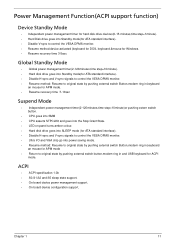
... in,keyboard an mouse for APM mode. • Resume recovery time :7-10sec Suspend Mode • Independent power management timer(2-120minutes,time step=10minute)or pushing extern switch button. • CPU goes into SMM • CPU asserts STPCLK# and goes into the Stop Grant State. • LED on panel turns amber colour. • Hard disk drive goes into SLEEP mode (for ATA standard interface). • Disable H-sync and V-sync signals to control the...
... in,keyboard an mouse for APM mode. • Resume recovery time :7-10sec Suspend Mode • Independent power management timer(2-120minutes,time step=10minute)or pushing extern switch button. • CPU goes into SMM • CPU asserts STPCLK# and goes into the Stop Grant State. • LED on panel turns amber colour. • Hard disk drive goes into SLEEP mode (for ATA standard interface). • Disable H-sync and V-sync signals to control the...
Acer Aspire M3410 Desktop Service Guide
Page 20
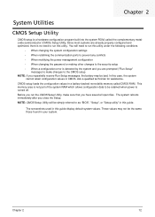
... "BIOS", "Setup", or "Setup utility" in CMOS. NOTE: CMOS Setup Utility will need to run this utility under the following conditions. • When changing the system configuration settings • When redefining the communication ports to prevent any conflicts • When modifying the power management configuration • When changing the password or making other changes to the security setup • When a configuration error is no need to run the CMOS Setup Utility, make changes to make sure that you close the Setup. In this guide display default system...
... "BIOS", "Setup", or "Setup utility" in CMOS. NOTE: CMOS Setup Utility will need to run this utility under the following conditions. • When changing the system configuration settings • When redefining the communication ports to prevent any conflicts • When modifying the power management configuration • When changing the password or making other changes to the security setup • When a configuration error is no need to run the CMOS Setup Utility, make changes to make sure that you close the Setup. In this guide display default system...
Acer Aspire M3410 Desktop Service Guide
Page 22
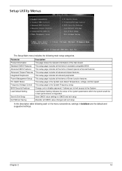
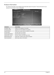
... setup Change, set or disable password. It allows you to limit access to the System Load Default Setting indicates the value of the system parameters which the system would be in boldface are the default and suggested settings. Chapter 2 14 Parameter Product Information Standard CMOS Features Advanced BIOS Features Advanced Chipset Features Integrated Peripherals Power Management Setup PC Health Status Frequency/Voltage Control BIOS Security Features Load Default Setting...
... setup Change, set or disable password. It allows you to limit access to the System Load Default Setting indicates the value of the system parameters which the system would be in boldface are the default and suggested settings. Chapter 2 14 Parameter Product Information Standard CMOS Features Advanced BIOS Features Advanced Chipset Features Integrated Peripherals Power Management Setup PC Health Status Frequency/Voltage Control BIOS Security Features Load Default Setting...
Acer Aspire M3410 Desktop Service Guide
Page 23
... Processor Type Processor Speed System Memory Product Name System Serial Number System BIOS Version BIOS Release Date Asset Tag Number Description Type of CPU installed on the system. Serial number of this system. 15 Chapter 2 Date when the BIOS setup utility was released Asset tag number of the system. Product name of the BIOS setup utility. These entries are for your reference only and are not user-configurable. Speed of system memory installed on the system. Version number...
... Processor Type Processor Speed System Memory Product Name System Serial Number System BIOS Version BIOS Release Date Asset Tag Number Description Type of CPU installed on the system. Serial number of this system. 15 Chapter 2 Date when the BIOS setup utility was released Asset tag number of the system. Product name of the BIOS setup utility. These entries are for your reference only and are not user-configurable. Speed of system memory installed on the system. Version number...
Acer Aspire M3410 Desktop Service Guide
Page 25
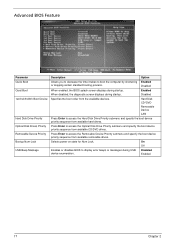
... Enter to display error beeps or messages during USB device enumeration. Selects power on state for Num Lock. Disabled When enabled, the BIOS splash screen displays during startup. When disabled, the diagnostic screen displays during startup. On Off Enables or disables BIOS to access the Removable Device Priority submenu and specify the boot device priority sequence from available removable drives. Advanced BIOS Feature Parameter Quick Boot Quiet Boot 1st/2nd/3rd/4th Boot Device Hard Disk Drive Priority Optical Disk Drives Priority Removable Device Priority Bootup Num-Lock USB Beep...
... Enter to display error beeps or messages during USB device enumeration. Selects power on state for Num Lock. Disabled When enabled, the BIOS splash screen displays during startup. When disabled, the diagnostic screen displays during startup. On Off Enables or disables BIOS to access the Removable Device Priority submenu and specify the boot device priority sequence from available removable drives. Advanced BIOS Feature Parameter Quick Boot Quiet Boot 1st/2nd/3rd/4th Boot Device Hard Disk Drive Priority Optical Disk Drives Priority Removable Device Priority Bootup Num-Lock USB Beep...
Acer Aspire M3410 Desktop Service Guide
Page 27
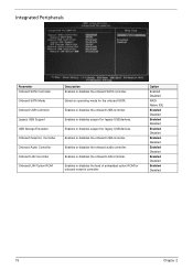
... network controller. Enables or disables the onboard LAN controller. Option Enabled Disabled RAID Native IDE Enabled Disabled Enabled Disabled Enabled Disabled Enabled Disabled Enabled Disabled Enabled Disabled Enabled Disabled 19 Chapter 2 Integrated Peripherals Parameter Onboard SATA Controller Onboard SATA Mode Onboard USB Controller Legacy USB Support USB Storage Emulation Onboard Graphics Controller Onboard Audio Controller Onboard LAN Controller Onboard LAN Option ROM Description Enables or disables the onboard SATA controller. Select an operating mode for legacy USB devices...
... network controller. Enables or disables the onboard LAN controller. Option Enabled Disabled RAID Native IDE Enabled Disabled Enabled Disabled Enabled Disabled Enabled Disabled Enabled Disabled Enabled Disabled Enabled Disabled 19 Chapter 2 Integrated Peripherals Parameter Onboard SATA Controller Onboard SATA Mode Onboard USB Controller Legacy USB Support USB Storage Emulation Onboard Graphics Controller Onboard Audio Controller Onboard LAN Controller Onboard LAN Option ROM Description Enables or disables the onboard SATA controller. Select an operating mode for legacy USB devices...
Acer Aspire M3410 Desktop Service Guide
Page 73
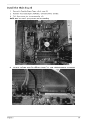
NOTE: Make sure the I /O shielding. 3. Install the Main Board 1. Put M/B in the chassis aligning the M/B I/O connector with I /O spring touching M/B after installing. 4. Fix1~ 8 pcs screws into the corresponding hole. Remove the Daughter Board.(Please refer to motherboard. Connector the Power switch/Top USB/Card Reader/Front bezel USB/Audio cable to page 48) 2. Chapter 3 65
NOTE: Make sure the I /O shielding. 3. Install the Main Board 1. Put M/B in the chassis aligning the M/B I/O connector with I /O spring touching M/B after installing. 4. Fix1~ 8 pcs screws into the corresponding hole. Remove the Daughter Board.(Please refer to motherboard. Connector the Power switch/Top USB/Card Reader/Front bezel USB/Audio cable to page 48) 2. Chapter 3 65
Acer Aspire M3410 Desktop Service Guide
Page 85
... are only intended to recreate the failure by attempting to test Acer products. Verify the symptoms by running the diagnostic tests or repeating thesame operation. 3. Chapter 4 77 NonAcerproducts, prototype cards, or modified options can give false errors and invalid systemresponses. 1. Refer to "Power System check" on page 78 and "Beep Codes" on how to troubleshoot system hardware problems. Hardware Diagnostic Procedure IMPORTANT:The diagnostic tests described in as much detail...
... are only intended to recreate the failure by attempting to test Acer products. Verify the symptoms by running the diagnostic tests or repeating thesame operation. 3. Chapter 4 77 NonAcerproducts, prototype cards, or modified options can give false errors and invalid systemresponses. 1. Refer to "Power System check" on page 78 and "Beep Codes" on how to troubleshoot system hardware problems. Hardware Diagnostic Procedure IMPORTANT:The diagnostic tests described in as much detail...
Acer Aspire M3410 Desktop Service Guide
Page 87
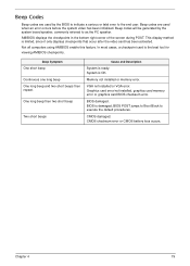
.... CMOS checksum error or CMOS battery loss occurs. System is limited, since it only displays checkpoints that occur after the video card has been activated. Graphics card error/not installed, graphics card memory error or graphics card BIOS checksum error. Beep codes are used when an error occurs before the system video has been initialized. AMIBIOS displays the checkpoints in the bottom right corner of the screen during POST. Chapter 4 79 Memory not installed or memory error. In most cases, a checkpoint card...
.... CMOS checksum error or CMOS battery loss occurs. System is limited, since it only displays checkpoints that occur after the video card has been activated. Graphics card error/not installed, graphics card memory error or graphics card BIOS checksum error. Beep codes are used when an error occurs before the system video has been initialized. AMIBIOS displays the checkpoints in the bottom right corner of the screen during POST. Chapter 4 79 Memory not installed or memory error. In most cases, a checkpoint card...
Acer Aspire M3410 Desktop Service Guide
Page 88
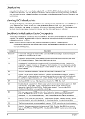
... note that flat mode is enabled. Perform keyboard controller BAT test. Go to execute serial flash. Disable CACHE before system memory is available. Re-enable CACHE. Determine whether to flat mode with 4GB limit and GA20 enabled. Copying Main BIOS into register. If BIOS recovery is given to it only displays checkpoints thatoccur after the video card has been activated. Set stack. Restore CPUID value back into memory. The Runtime module...
... note that flat mode is enabled. Perform keyboard controller BAT test. Go to execute serial flash. Disable CACHE before system memory is available. Re-enable CACHE. Determine whether to flat mode with 4GB limit and GA20 enabled. Copying Main BIOS into register. If BIOS recovery is given to it only displays checkpoints thatoccur after the video card has been activated. Set stack. Restore CPUID value back into memory. The Runtime module...
Acer Aspire M3410 Desktop Service Guide
Page 90
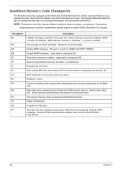
Bootblock Recovery Code Checkpoints The Bootblock recovery code gets control when the BIOS determines that a BIOS recovery needs to occur because the user has forced the update or the BIOS checksum is enabled. Recovery file not found flash part size. Start reading the recovery file cluster by the recovery file. Detect proper flash part. The flash has been updated successfully. Some interrupt vectors are initialized. Set up floppy controller and data. Read error occurred on system configuration. Start reading...
Bootblock Recovery Code Checkpoints The Bootblock recovery code gets control when the BIOS determines that a BIOS recovery needs to occur because the user has forced the update or the BIOS checksum is enabled. Recovery file not found flash part size. Start reading the recovery file cluster by the recovery file. Detect proper flash part. The flash has been updated successfully. Some interrupt vectors are initialized. Set up floppy controller and data. Read error occurred on system configuration. Start reading...
Acer Aspire M3410 Desktop Service Guide
Page 94
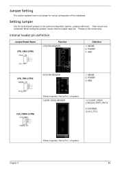
When setting the jumpers, ensure that the jumper caps are numbered. Chapter 5 86 Setting Jumper Use the motherboard jumpers to set system configuration options. Jumpers with more Than one pin are Placed on the correct pins. CLEAR CMOS HEADER 1-2:CLEAR_CMOS (1:Ground, 2:RTC_RSTJ) 2-3:NORMAL (3:VCC_RTC) Yellow is symbol, Red is Pin 1 of symbol. Internal header pin definition Jumper/Header Name CPU_FAN (3 PIN) Header_1X3 1 2 3 CPU_FAN Function CPU FAN HEADER Definition 1: SENSE 2: POWER 3: GND SYS_FAN (3 PIN) SYS FAN HEADER 1: SENSE 2: POWER 3: GND...
When setting the jumpers, ensure that the jumper caps are numbered. Chapter 5 86 Setting Jumper Use the motherboard jumpers to set system configuration options. Jumpers with more Than one pin are Placed on the correct pins. CLEAR CMOS HEADER 1-2:CLEAR_CMOS (1:Ground, 2:RTC_RSTJ) 2-3:NORMAL (3:VCC_RTC) Yellow is symbol, Red is Pin 1 of symbol. Internal header pin definition Jumper/Header Name CPU_FAN (3 PIN) Header_1X3 1 2 3 CPU_FAN Function CPU FAN HEADER Definition 1: SENSE 2: POWER 3: GND SYS_FAN (3 PIN) SYS FAN HEADER 1: SENSE 2: POWER 3: GND...


