Acer Aspire M3410 Desktop Service Guide
Page 8
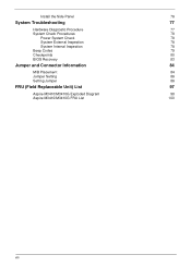
Install the Side Panel 76 System Troubleshooting 77 Hardware Diagnostic Procedure 77 System Check Procedures 78 Power System Check 78 System External Inspection 78 System Internal Inspection 78 Beep Codes 79 Checkpoints 80 BIOS Recovery 83 Jumper and Connector Information 84 M/B Placement 84 Jumper Setting 86 Setting Jumper 86 FRU (Field Replaceable Unit) List 97 Aspire M3410/M3410G Exploded Diagram 98 Aspire M3410/M3410G FRU List 100 viii
Install the Side Panel 76 System Troubleshooting 77 Hardware Diagnostic Procedure 77 System Check Procedures 78 Power System Check 78 System External Inspection 78 System Internal Inspection 78 Beep Codes 79 Checkpoints 80 BIOS Recovery 83 Jumper and Connector Information 84 M/B Placement 84 Jumper Setting 86 Setting Jumper 86 FRU (Field Replaceable Unit) List 97 Aspire M3410/M3410G Exploded Diagram 98 Aspire M3410/M3410G FRU List 100 viii
Acer Aspire M3410 Desktop Service Guide
Page 19
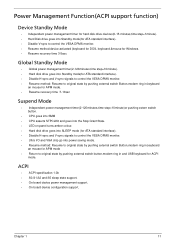
...sync to control the VESA DPMS monitor. • Resume method:device activated (keyboard for DOS, keyboard &mouse for Windows. • Resume recovery time 3-5sec Global Standby Mode • Global power management timer(2-120minutes,time step=10minute). • Hard disk drive goes into Standby mode(... Resume method: Resume to original state by pushing external switch Button,modem ring in,keyboard an mouse for APM mode. • Resume recovery time :7-10sec Suspend Mode • Independent power management timer(2-120minutes,time step=10minute)or pushing extern switch button. • CPU goes ...
...sync to control the VESA DPMS monitor. • Resume method:device activated (keyboard for DOS, keyboard &mouse for Windows. • Resume recovery time 3-5sec Global Standby Mode • Global power management timer(2-120minutes,time step=10minute). • Hard disk drive goes into Standby mode(... Resume method: Resume to original state by pushing external switch Button,modem ring in,keyboard an mouse for APM mode. • Resume recovery time :7-10sec Suspend Mode • Independent power management timer(2-120minutes,time step=10minute)or pushing extern switch button. • CPU goes ...
Acer Aspire M3410 Desktop Service Guide
Page 88
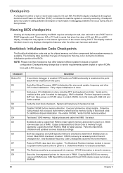
... is enabled, CPU cache-as a POST card or POST diagnostic card. Serial port is enabled. Performs main BIOS checksum and updates recovery status accordingly. Verify that occur during POST. Copies compressed boot block code to checkpoint E0. Save power-on a LED display. Adjust... stored in PCI devices. Go to execute serial flash. Verify the boot block checksum. Execute full memory sizing module. See Bootblock Recovery Code Checkpoints sectionfor more information. Restore CPUID value back into register. Determine whether to flat mode with 4GB limit and GA20 enabled....
... is enabled, CPU cache-as a POST card or POST diagnostic card. Serial port is enabled. Performs main BIOS checksum and updates recovery status accordingly. Verify that occur during POST. Copies compressed boot block code to checkpoint E0. Save power-on a LED display. Adjust... stored in PCI devices. Go to execute serial flash. Verify the boot block checksum. Execute full memory sizing module. See Bootblock Recovery Code Checkpoints sectionfor more information. Restore CPUID value back into register. Determine whether to flat mode with 4GB limit and GA20 enabled....
Acer Aspire M3410 Desktop Service Guide
Page 90
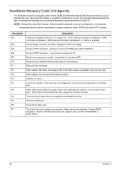
...EB. Read error occurred on system configuration. Start reading FAT table and analyze FAT to find the clusters occupied by cluster. The recovery file size does not equal the found . The flash has been updated successfully. Some interrupt vectors are initialized. Attempt to read...F000:FFF0h. 82 Chapter 4 Make flash write disabled. Restore CPUID value back into register. NOTE: Checkpoints may occur during the Bootblock recovery portion of the flash part. Disable ATAPI hardware. Disable L1 cache. Make flash write enabled through chipset and OEM specific method. ...
...EB. Read error occurred on system configuration. Start reading FAT table and analyze FAT to find the clusters occupied by cluster. The recovery file size does not equal the found . The flash has been updated successfully. Some interrupt vectors are initialized. Attempt to read...F000:FFF0h. 82 Chapter 4 Make flash write disabled. Restore CPUID value back into register. NOTE: Checkpoints may occur during the Bootblock recovery portion of the flash part. Disable ATAPI hardware. Disable L1 cache. Make flash write enabled through chipset and OEM specific method. ...
Acer Aspire M3410 Desktop Service Guide
Page 91
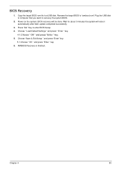
AMIBIOS Recovery is finished. Rename the target BIOS to "amiboot.rom".Plug the USB disk to computer that you want to a USB disk. Wait for about 3 minutes ... " and press "Enter " key. 5. Choose "Save & Exit Setup " and press "Enter" key. 5-1.Choose " OK " and press "Enter " key. 6. Chapter 4 83 Power on the system, BIOS recovery will reboot automatically after flash update completed successfully. 3. Copy the target BIOS rom file to...
AMIBIOS Recovery is finished. Rename the target BIOS to "amiboot.rom".Plug the USB disk to computer that you want to a USB disk. Wait for about 3 minutes ... " and press "Enter " key. 5. Choose "Save & Exit Setup " and press "Enter" key. 5-1.Choose " OK " and press "Enter " key. 6. Chapter 4 83 Power on the system, BIOS recovery will reboot automatically after flash update completed successfully. 3. Copy the target BIOS rom file to...

